Shure Incorporated
8/38
◦
◦
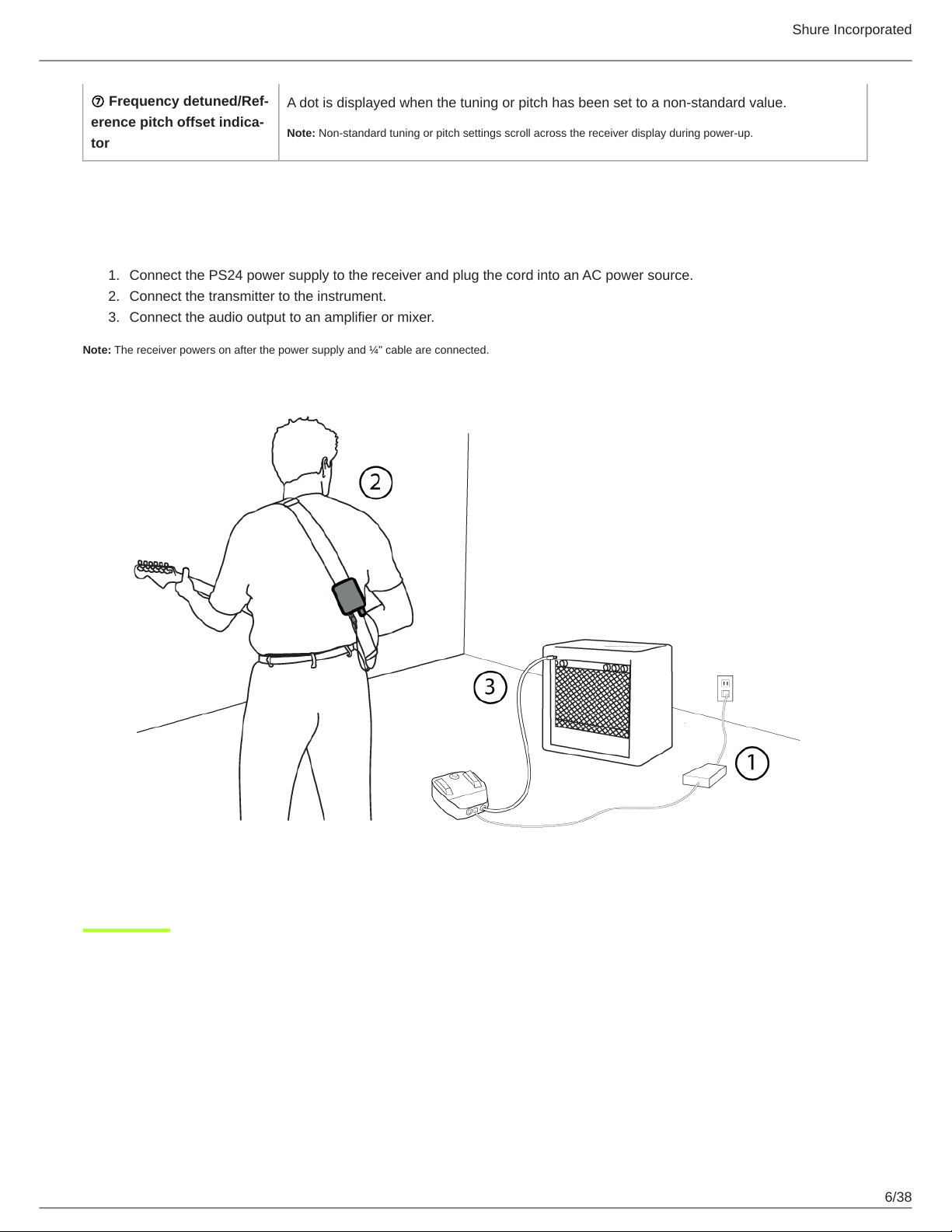
1.
2.
3.
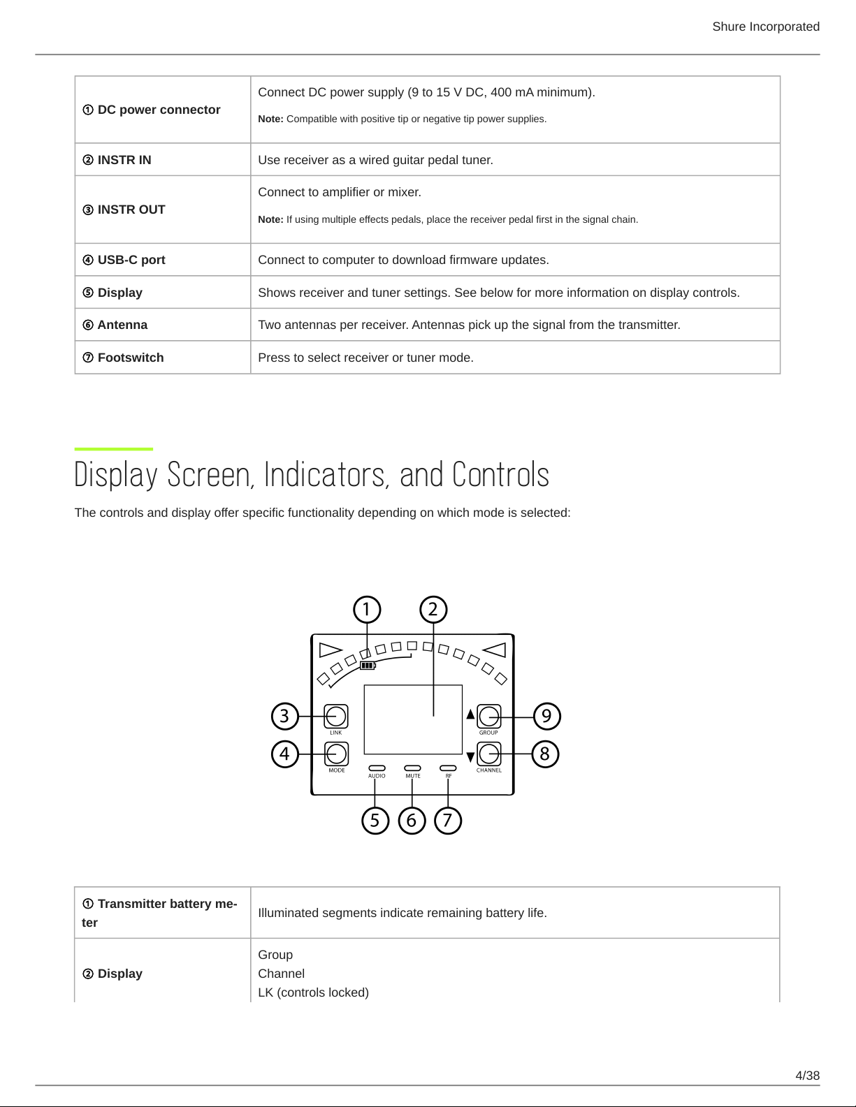
⑥Link button
Press and hold within 5 seconds of power-on to manually link with receiver.
Press momentarily to activate remote ID function.
⑦Battery compartment
Holds 1 Shure rechargeable battery.
Transmitter Status LED
LED is green during normal operation.
LED color or flashing indicates a change in transmitter status as shown in the following table:
Color State Description
Green
Flashing (slow) Transmitter attempting relink with receiver
Flashing (fast) Unlinked transmitter searching for receiver
Flashes 3 times Indicates locked transmitter when power switch is pressed
Red
On Battery life < 1 hour
Flashing Battery life < 30 minutes
Red/Green Flashing Remote ID active
Amber Flashing Battery error; remove and insert again, or replace battery
Wearing the Bodypack
Clip the bodypack to a belt or slide a guitar strap through the bodypack clip as shown.
For best results, the belt should be pressed against the base of the clip.
Install Transmitter Batteries
Important: Always fully charge a new battery before first use.
Move the locking lever to the open position and slide the battery door open.
Place the battery into the transmitter.
Close the battery door.