SI 201576 User manual

DECOSET KEYPAD
Installation Instructions
# 201576
SET UPPER
SET LOWER
REVERSE
UP
DOWN
STOP

Thank you for purchasing an SI product. If you have any
questions or need any assistance with your Decoset, we
would love to help you.
Technical Support: 512.832.6939
Hours of Support: 7:30am - 5pm CST
screeninnovations.com
Decoset
Please use these QR Codes to access the updated
installation instructions and video tutorials.

CONTENTS

4
PARTS IN THE BOX
8 button keypad
- base
Parts in the Box
White trim
wall plate
(2)Trim plate screws (2)Insert screws
(1)Decoset interface
8 button
Decora insert
5 button
Decora insert
(1) Cate 5e cable
485 Motor Interface
485 Motor only

5
INITIAL CONSIDERATIONS
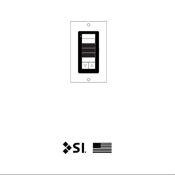
The Decoset is a pre-programmed control keypad/limit
setting tool. And is designed to allow you to set the limits
and adjust the rotation on your 485 screen/shade without
the use of a PC or any other hardware.
Once you complete your setup, then the keypad can be used
to control the 485 screen/shade and installed in a wall.
Initial considerations & Setup steps
SETUP STEPS
Review the following pages (6 - 8) to determine if your
screen/shade is an AC or Low-Voltage powered.
If you already know that you have a Low-Voltage screen
then skip to page 9.

6
WIRING TOPOLOGY - AC 485
SCREENS
Wiring topology - AC 485 screens
3 conductors
(up to100') Decoset
Interface
Terminal
Block
RJ45
Solo/Pro 2 screen
AC Power
Supply
485 Motor Interface
485 Motor only
V+
V-
+
-
G

7
CONNECTING TO AC 485 SCREENS
1. Connect the Terminal Block coming from your screen
to the 485 interface
2. You can now connect your Decoset to the keypad port
of the interface.
Note: If you need to extend the length of cable to your
Decoset, you can use standard Cat5e up to 100 ft.
Connecting to AC 485 screens

8
3. Once your Decoset is connected to the screen and the
screen has AC power applied, a small red LED will start
flashing directly above the RJ45 connector on the back of
the Decoset.
Note: If this does not happen, then check the AC power
You're now ready to start configuring your screen/shade.
Skip to Page 15 for next steps.
Connecting to AC 485 screens
Flashing Red LED to
indicate power

9
WIRING TOPOLOGY - LV 485
MOTORS
Power Supply
Cat 5e
(100ft)
Decoset
Solo/Pro 2 screen / Nano shades
Note: Most all LV motors will come with a cable terminated
into a 5 position terminal block.
V+
V-
+
-
G
V+
V-
+
-
G
Wiring topology - LV 485 motors
485 Motor Interface
485 Motor only
Note: The 485 Motor Interface power LED will illuminate
green whenever LV power is applied to your shade/screen.

10
CONNECTING TO LV 485 MOTORS
1. The included 485 Motor Interface provides connections
for the 5 conductor wire coming from the screen/shade
and the wire coming from the low-voltage power supply
and a connection for Decoset via Cat5e.
2. Make all the 485 Moto Interface connections first, then
apply power via low-voltage power supply.
485 Moto Interface
From the
screen/
shade
RJ45
V+
V-
+
-
G
To low-Voltage power supply
+ 24 VDC
- 24 VDC
Not
used
V+V+
V-V-
++
--
GG
Connecting to LV 485 motors
485 Motor Interface
485 Motor only

11
3. A small red LED will start flashing directly above the
RJ45 connector on the back of the Decoset.
voltage
Connecting to LV 485 motors
Flashing Red LED to
indicate power
Momentary
UP
Momentary
DOWN
Momentary
STOP
Decoset has optional Dry Contact closure inputs on rear of
keypad for UP, Down, and Stop.
S
CG UP
DN
CG

12
Pressing UP will send
motor to the Upper limit.
- Pressing STOP will stop
any motor movements.
- Holding STOP will send
motor to first IP (if set).
Pressing DOWN will send
motor to the Lower limit.
The command status LED will flash once per movement (button
press) or in other words for each command sent to motor.
SET UPPER
SET LOWER
REVERSE
UP
DOWN
STOP
DECOSET MOVEMENT
COMMANDS (WHITE BUTTONS
& LED)
- Pressing will send
small movement down
to motor.
- Holding will
continuously move motor
down.
- Releasing will stop
the motor down motion.
- Pressing will send small
movement up to motor.
- Holding will continuously
move motor up.
- Releasing will stop
the motor up motion.
Decoset Movement commands (white buttons & LED)

13
The command status LED
Holding SET UPPER will
continuously move motor up
(even past the current upper
limit).
Releasing SET UPPER will
set motor upper limit to the
current position.
Holding SET LOWER will
continuously move motor
down (even past the current
lower limit).
Releasing SET LOWER will
set motor lower limit to the
current position.
SET UPPER
SET LOWER
REVERSE
UP
DOWN
STOP
DECOSET SETTING COMMANDS
(BLACK BUTTONS)
Holding REVERSE will change
the rotation of the motor.
Decoset Setting commands (Black buttons)

14
3. Make screen/shade adjustments
Screen/shades have upper and lower limits set at the
factory. The typical screen installation should not require the
upper limit being modified, however the lower limit is often
modified, using 1 of the following 2 methods:
a. Adjusting lower limit to a new higher position
- Press the DOWN button on the Decoset to move the
screen to the current lower limit.
- Press and hold until you reach the desired position.
- Optionally, pressing or holding either of the or will
move the screen accordingly.
- Finally, hold the SET LOWER button until you see the
status LED flash twice. Now, release to save the current
position as the new lower limit.
b. Adjusting lower limit to a new lower position
- Press the DOWN button on the Decoset to move the
screen to the current lower limit.
- Press and hold the SET LOWER button until you achieve
the desired position and when you release the button,
the lower limit is now set to the current position.
Decoset Setting commands (Black buttons)

15
4. Change motor rotation if needed
Screen/shades have the correct motor rotations set at the
factory. The typical screen installation should not require the
motor rotation being modified. If directed by SI support the
following method, will allow you to change the rotation.
- Hold the REVERSE button on the Decoset until you see
the Command LED flash once. Then release the button.
- Repeat the above step 2 more times.
After the 3rd time, the rotation of the motor has now been
reversed.
Decoset Setting commands (Black buttons)

16

17
DECOSET CONFIGURATION FOR
END USER CONTROL
When all limit settings have been completed you can
mechanically congure the keypad for control only mode.
Note: Never permanently
install the Decoset with 3
place.
Control ModeSettings Mode
SET UPPER
SET LOWER
REVERSE
UP
DOWN
STOP
UP
DOWN
STOP
Decoset configuration for end user control

18
Using a thin athead
screwdriver press in the 4 tabs
along the side of the base unit
to remove the 8 button Decora
insert.
Remove the 3 black settings
buttons from base and store in
DecoSET box
Step 1.
Step 2.
Decoset configuration for end user control

19
Place 5 button Decora insert
back on base snapping-in all 4
tabs on the sides
Decoset now ready to be
installed in a 1-gang wall
box with White trim to nish
permanently
Step 3.
Step 4.
Decoset configuration for end user control

20
TROUBLESHOOTING
Problem Possible Cause Action to Take
The LED on
the rear of the
Decoset is
not ashing
No power. For AC motors, check the
line voltage input.
For LV motors, check the
low-voltage power supply
The motor
doesn't
respond
to the
movement
(white)
buttons
No limits have
been set.
Connection
issue on
the Decoset
dongle.
Verify limits have been set
or set new limits.
Verify the connection
between the screen/
shade and the Decoset
dongle.
AC screen
doesn't have
4 conductors
Older screen You will need to purchase
a low-voltage power
supply #1822209 from SI.
Troubleshooting
This manual suits for next models
1
Table of contents
Other SI Keypad manuals