Siare AM5000 User manual

AM5000 – AM5000/3 – AM5000/5
Service Manual
AM5000 - AM5000/3 - AM5000/5
ANAESTESIA MODULE
SERVICE MANUAL
AM5000
AM5000/3
AM5000/5
P.N.: DU5506130 Page 1 of 34 Rev.: 3.0
دﯾﯾﺎﻣرﻓ ﮫﻌﺟارﻣ.WWW.ELM-FAN.IRتﯾﺎﺳ ﮫﺑ رﺗﺷﯾﺑ دراوﻣ دوﻠﻧاد یارﺑ
To download more items, go to ELM-FAN.IR

AM5000 – AM5000/3 – AM5000/5
Service Manual
GENERAL INDEX
1. USE OF SERVICE MANUAL.................................................................................................................3
1.1 U er of Manual................................................................................................................................3
1.2 De cription of u e.............................................................................................................................3
1.3 Safety Note .....................................................................................................................................3
2. MAINTENANCE PROCEDURES...........................................................................................................5
2.1 General Information..........................................................................................................................5
3. TECHNICAL DESCRIPTION.................................................................................................................6
3.1AM5000 AM5000/3 - AM5000/5 anae the ia module.......................................................................6
3.2 The Pneumatic Di tributor................................................................................................................8
4. CALIBRATION AND TESTING............................................................................................................13
4.1 Flowmeter Box................................................................................................................................13
4.2 Final Te t........................................................................................................................................24
5. PNEUMATICS......................................................................................................................................29
5.1 Pneumatic Diagram AM5000..........................................................................................................29
5.2 Component Li t FOR AM 5000/....................................................................................................30
5.3 Pneumatic Diagram AM5000/3.......................................................................................................31
5.4 Component Li t FOR AM 5000/3..................................................................................................32
5.5 Pneumatic Diagram AM5000/5.......................................................................................................33
5.6 Component Li t FOR AM 5000/5..................................................................................................34
Warning
SIARE i u ed throughout thi manual a an abbreviation for
SIARE HOSPITAL SUPPLIES S.r.l.
Via Giulio Pastore, 18 40056 Crespellano (BO) ITALY
Tel.:+39 051/969802
Fax: +39 051/969101
Manufacturer of the equipment described in this manual
P.N.: DU5506130 Page 2 of 34 Rev.: 3.0
دﯾﯾﺎﻣرﻓ ﮫﻌﺟارﻣ.WWW.ELM-FAN.IRتﯾﺎﺳ ﮫﺑ رﺗﺷﯾﺑ دراوﻣ دوﻠﻧاد یارﺑ
To download more items, go to ELM-FAN.IR

AM5000 – AM5000/3 – AM5000/5
Service Manual
1. USE OF SERVICE MANUAL
1.1 Users of Manual
Thi manual i trictly for u e by SIARE technician or qualified technician authorized by SIARE:
The technician authorized by SIARE ha available the appropriate tool and pare part and i trained with
regard to the afety of the product.
SIARE decline all re pon ibility with regard to technical a i tance to the unit without formal authorization
of SIARE.
The correct and afe u e for the patient and the operator of the unit, require the knowledge of the
in truction and advice written in thi manual and the U er’ manual.
1.2 Description of use
The ymbol
!
placed near an in truction, call the reader’ attention to important information regarding
the afety of the patient and operator.
The manual de cribe the unit and it operation with the help of electrical and pneumatic diagram .
The U er’ manual i an integral part of thi manual, and the technician hould have available a copy of the
U er’ manual and hould known it content before performing any of the operation de cribed in thi
manual.
1.3 Safety Notes
WARNINGS
The unit ha been de igned and i manufactured in condition that guarantee the quality of the product and
it component , in order to en ure the maximum level of reliability and the afety of the patient and the
operator.
Therefore it afety i guaranteed only if it i u ed a per the in truction contained in thi manual and the
U er’ manual which i an integral and un eparable part of the product documentation for the technical
a i tance.
For afety rea on , it i nece ary to trictly follow the cheduled maintenance de cribed in the U er’
manual.
The maintenance and the replacement of any part ha to be performed by authorized SIARE ervice
dealer and only original SIARE part or part checked by SIARE hould be u ed.
SIARE i not civically or criminally liable in the following ca e :
1) U e in condition and for rea on not tated or pre cribed in thi manual.
2) Lack or omi ion of cheduled maintenance a de cribed in thi manual.
3) Maintenance performed by per onnel not authorized by SIARE.
4) U e of non original pare part or pare part not checked and approved by SIARE.
5) Connection with equipment that i not in compliance with relevant directive in effect.
P.N.: DU5506130 Page 3 of 34 Rev.: 3.0
دﯾﯾﺎﻣرﻓ ﮫﻌﺟارﻣ.WWW.ELM-FAN.IRتﯾﺎﺳ ﮫﺑ رﺗﺷﯾﺑ دراوﻣ دوﻠﻧاد یارﺑ
To download more items, go to ELM-FAN.IR

AM5000 – AM5000/3 – AM5000/5
Service Manual
!
Do not use the equipment in the presence of flammable gases.
In order to avoid ri k of explo ion thi unit hould not be u ed in the in the pre ence of flammable
anae thetic ga e uch a ether of ciclopropane. Thi unit can operate only with ane thetic that are not
flammable a per the directive relative to the electrical afety of the anae the ia unit .
!
Do not connect the unit to the patient using conductive antistatic tubes.
Due to the fact that thi machine cannot be u ed with flammable anae thetic agent , uch a ether or
ciclopropane, the u e of anti tatic patient tube i not nece ary. Since the u e of anit tatic tube can cau e
burn when u ing urgical equipment at high frequencie , their u e i not allowed in any admini tration with
thi equipment.
!
The unit is not approved for use in areas with danger of explosion.
The unit cannot be used in the presence of explosive gases.
Before connecting the unit with other electrical equipment not described in this
manual, check with the manufacturer.
Regarding electro medical equipment’s general safety, it is important to follow all rules regarding the
interaction between the equipment and the patient, the operator and the nearby environment.
In order to ensure proper and safe use of the equipment it is crucial to follow the instructions in this
manual and the User’s manual and pay attention to the notes furnished in this User’s manual.
In order to use this equipment, it is vital to know all the instructions in this manual.
The equipment should be inspected and the maintenance performed by SIARE authorized personnel
every 6 (six) months. All maintenance performed by SIARE authorized personnel is recorded in the
equipment’s maintenance log.
Every repair should be performed by SIARE authorized personnel. Siare is not liable for direct or
indirect damage to people or things, due to technical assistance by personnel non authorized by
SIARE or improper use of the equipment, that is to say a use not described in the User’s manual or
technical manual.
In order to repair equipment that i malfunctioning, ha defect or i broken, the operator hould contact
SIARE or it authorized local ervice dealer. It i important, when reque ting ervice, to pecify the model
and erial number of the equipment.
U e only the recommended acce orie .
The u e of other acce orie i authorized only by a written authorization from SIARE a per the afety
directive in effect.
The equipment’ operation i authorized only in area that conform to the afety directive in effect.
P.N.: DU5506130 Page 4 of 34 Rev.: 3.0
دﯾﯾﺎﻣرﻓ ﮫﻌﺟارﻣ.WWW.ELM-FAN.IRتﯾﺎﺳ ﮫﺑ رﺗﺷﯾﺑ دراوﻣ دوﻠﻧاد یارﺑ
To download more items, go to ELM-FAN.IR

AM5000 – AM5000/3 – AM5000/5
Service Manual
2. MAINTENANCE PROCEDURES
2.1 General Information
!
In order to en ure the afety of the patient and the operator, the unit hould undergo an in pection
and te t after 800 hour of u e or every 6 month , whichever come fir t. The in pection and te t require a
pecific knowledge of the unit, and therefore have to be made by pecially trained SIARE authorized
per onnel.
The ane theti t or doctor i re pon ible for the ordinary maintenance of the unit, a de cribed in thi chapter.
Cleaning, di infecting, terilization and replacement of part hould be done a per the in truction in the
u er’ manual in order to avoid damage to the equipment that could al o endanger the afety of the patient
and operator.
The component u ed have been elected after technical and comparative te t in the de igning pha e of
the machine.
Furthermore, the ame component are alway te ted during the manufacturing cycle in order to obtain the
maximum level of afety and reliability for the operator and patient.
Therefore whenever a part need to be replaced, it mu t be an original pare part, which ha been checked
and te ted by SIARE.
SIARE a ume re pon ibility for all provi ion of the law, if the unit i u ed and maintained a per the
in truction in thi manual and the technical manual. The Technical A i tance Report, igned by the
authorized SIARE technician, i proof of the completion of the cheduled maintenance.
P.N.: DU5506130 Page 5 of 34 Rev.: 3.0
دﯾﯾﺎﻣرﻓ ﮫﻌﺟارﻣ.WWW.ELM-FAN.IRتﯾﺎﺳ ﮫﺑ رﺗﺷﯾﺑ دراوﻣ دوﻠﻧاد یارﺑ
To download more items, go to ELM-FAN.IR

AM5000 – AM5000/3 – AM5000/5
Service Manual
3. TECHNICAL DESCRIPTION
3.1AM5000 AM5000/3 AM5000/5 anaesthesia module
AM5000 - AM5000/3 – AM5000/5 regulate the upply and concentration of the ga mixture (Air, O2, N2O),
and al o upplie it to the anae thetic ga vaporizer.
It al o allow the election of the ga mixture to be upplied (Air-O2, or N2O-O2) and the enrichment (with
oxygen) of the upplied ga mixture for emergencie . The AM5000 - AM5000/3 – AM5000/5 i al o equipped
with the MIX-LIFE device that guarantee a minimum of 25% oxygen in all open-tap condition .
By u ing the three gauge located on the front panel, the medical ga e upply pre ure coming from the
central ga in tallation can be continuou ly controlled (preci ion ± 10%).
The flowmeter permit the mea urement of the flow the of the corre ponding ga e with a preci ion of ±
10% of the di played value or ± 1% of the bottom of the cale, by choo ing the highe t of the two value .
I
L
O
S
T
P
Q
V
AM5000
I
L
M
N
O
S
T
U
P
Q
R
V
I
L
M
N
O
S
T
U
P
Q
R
V
AM5000/3
AM5000/5
W
X
Front view
I OXYGEN upply gauge.
L NITROUS OXIDE upply gauge.
M AIR upply gauge.
N Selector witch for AIR / NITROUS OXIDE. Thi afety device:
avoid the contemporaneou upply of air and nitrou oxide
only the elected ga will be available on the flowmeter .
O OXYGEN BY-PASS key. By pre ing thi key pure oxygen i relea ed into the anae the ia circuit with a
flow of approximately 60 l/min.
P OXYGEN flow regulator for fre h ga e . It open counter-clockwi e.
Q NITROUS OXIDE flow regulator for fre h ga e . It open counter-clockwi e.
P.N.: DU5506130 Page 6 of 34 Rev.: 3.0
دﯾﯾﺎﻣرﻓ ﮫﻌﺟارﻣ.WWW.ELM-FAN.IRتﯾﺎﺳ ﮫﺑ رﺗﺷﯾﺑ دراوﻣ دوﻠﻧاد یارﺑ
To download more items, go to ELM-FAN.IR

AM5000 – AM5000/3 – AM5000/5
Service Manual
The opening of thi regulator automatically upplie a flow of oxygen of about 25% of the total mixture.
The flow of oxygen can be viewed on flowmeter (S). Thi afety device (MIX LIFE) avoid the incorrect
admini tration of hypoxic mixture .
R AIR flow regulator for fre h ga e . It open counter-clockwi e.
S OXYGEN flowmeter (Max flow 12 l/min). In the model for low flow , there i a econd flowmeter (W)
with a lower cale of 1 liter.
T NITROUS OXIDE flowmeter (Max flow 12 l/min).. In the model for low flow , there i a econd
flowmeter (X) with a lower cale of 1 liter.
U AIR flowmeter (Max flow 12 l/min).
V Selector witch for the exit of fre h ga e (BREATHING SYSTEM or TO AND FRO).
A
B
D
E
H
G
F
I
AM5000
A
B
C
D
E
H
G
F
I
AM5000/3
AM5000/5
Back View
A OXYGEN inlet from the main medical ga in tallation.
B NITROUS OXIDE inlet from the main medical ga in tallation.
C COMPRESSED AIR inlet from the main medical ga in tallation.
D OXYGEN inlet from the cylinder’ pre ure reducer.
E NITROUS OXIDE inlet from the cylinder’ pre ure reducer.
F AIR/OXYGEN outlet for the upply of the lung ventilator, of the active cavenging y tem and the
tracheal a piration unit.
In optimal condition the e connector upply COMPRESSED AIR.
If there i no COMPRESSED AIR or there i not enough pre ure, the unit automatically witche the
di tribution to OXYGEN.
The e connector are upplied tandard with the machine if the relative acce orie are in u e
G Emergency OXYGEN outlet.
H Exit of fre h ga e connector for TO and FRO.
I FRESH GAS outlet for the Breathing System.
P.N.: DU5506130 Page 7 of 34 Rev.: 3.0
دﯾﯾﺎﻣرﻓ ﮫﻌﺟارﻣ.WWW.ELM-FAN.IRتﯾﺎﺳ ﮫﺑ رﺗﺷﯾﺑ دراوﻣ دوﻠﻧاد یارﺑ
To download more items, go to ELM-FAN.IR

AM5000 – AM5000/3 – AM5000/5
Service Manual
3.2 The Pneumatic Distributor
NOTE: THE HERE BELOW INDICATED SCHEMES AND THE PROCEDURES, HAVE BEEN UNIFIED
FOR THE THREE MODULES AM5000 – AM5000/3 – AM5000/5.
REMEMBER: DO NOT CONSIDER THE AIR LINE FOR ANAESTHESIA MODULE A 2 FLOWETERS.
Below i the pneumatic diagram which de cribe the unit:
The main purpo e of the pneumatic di tributor i to:
1. take the medical ga e form the pipeline connection or cylinder connection .
2. monitor the operating pre ure (pre ure gauge )
3. elect the type of mix that hould be admini tered to the patient (ga elector AIR-N20)
4. take the elected ga e to the flowmeter box
5. allow the mixed ga e to be taken to the patient ventilation y tem (breathing y tem)
6. enrich the oxygen mixture in ca e of need (O2 bypa )
All the upply inlet are protected by a non-return valve, in order to avoid a leak of ga in ca e there i no
upply.
P.N.: DU5506130 Page 8 of 34 Rev.: 3.0
3 3
1 2
1 2 2 4
1 2
1 2 2 4
3 2
1 2 3 2
8
1 1
1 2
1 0
6
2 8
9
2
5
13
2
1 5
21 0
8
3 0
1 2
2 3
2 8
9
2 8 1 0
1 3
1 3
1 4
1 5 1 5
1 6 1 6
1 7 1 7 1 7
1 8
1 8 1 8
1 8
1 9 1 9
2 0 2 0
2 1
2 2 2 2
2 9
4 5
2 5
2 6
2 7
O 2
N 2 O
A I R
T O F L O W M E T E R
F R O M
V A P O R I Z E R
A
B
C
D
1
3
4
1
3
2
4 4
4 4
4 4 4 4 4 4
دﯾﯾﺎﻣرﻓ ﮫﻌﺟارﻣ.WWW.ELM-FAN.IRتﯾﺎﺳ ﮫﺑ رﺗﺷﯾﺑ دراوﻣ دوﻠﻧاد یارﺑ
To download more items, go to ELM-FAN.IR

AM5000 – AM5000/3 – AM5000/5
Service Manual
A econdary function , it allow :
upplie an auxiliary outlet of only oxygen which i automatically clo ed for connection to reanimation bag
for emergencie ,
upplie auxiliary outlet for O2 and Air (Aux outlet Air/O2) for device uch a the lung ventilator, ventury
a pirator, etc...
The auxiliary outlet for Air/O2 upply medical air if it ha a pre ure higher than that of the oxygen minu
0.5 bar. The non-return valve 18 and 26 are nece ary in order to avoid that air and O2 mix due to the
pre ure difference between the two ga e ’ upply.
Each ga cylinder or pipeline upply conform to the DISS tandard in order to avoid mi take in identifying
the ga e .
The gauge have a colored band indicating the range at which there i the correct upply pre ure.
The ga e upplied to the AM5000 - AM5000/3-AM5000/5 are connected to the flowmeter box in order to
regulate the flow and to mix the ga e that are then ent to the anae thetic ga vaporizer . From the e they
are taken back to the AM5000 - AM5000/3-AM5000/5 in to later be ent to the connector for the fre h ga
upply in the patient ventilation circuit. The ga e mixed with the anae thetic can be later mixed with pure
oxygen for enrichment of the mix that can be done by the operator by u ing the bypa button.
The elector enable u ing two different type of breathing y tem without di connection between the
tube : the fir t i the patient circuit of the breathing y tem and the econd, i the To and Fro, which i u ed
for manual ventilation of the patient’ breathing apparatu .
P.N.: DU5506130 Page 9 of 34 Rev.: 3.0
دﯾﯾﺎﻣرﻓ ﮫﻌﺟارﻣ.WWW.ELM-FAN.IRتﯾﺎﺳ ﮫﺑ رﺗﺷﯾﺑ دراوﻣ دوﻠﻧاد یارﺑ
To download more items, go to ELM-FAN.IR

AM5000 – AM5000/3 – AM5000/5
Service Manual
The following diagram illu trate the connection between the part de cribed above, in thi ca e a
flowmeter box with three flowmeter .
F
L
O
W
M
E
T
E
R
O
AIR
2
N O
2
F
L
O
W
M
E
T
E
R
F
L
O
W
M
E
T
E
R
P.N.: DU5506130 Page 10 of 34 Rev.: 3.0
35
36 37 38
34
34
40
39 40
40
41
42
32
43
VAPORIZER
دﯾﯾﺎﻣرﻓ ﮫﻌﺟارﻣ.WWW.ELM-FAN.IRتﯾﺎﺳ ﮫﺑ رﺗﺷﯾﺑ دراوﻣ دوﻠﻧاد یارﺑ
To download more items, go to ELM-FAN.IR

AM5000 – AM5000/3 – AM5000/5
Service Manual
FLOWMETER BOX
Can be u ed in the two, three and five flowmeter model .
F
L
O
W
M
E
T
E
R
O
SAFETY
VALVE
TO
VAPORIZER
2
N O
REG.
PRESS.
REG.
PRESS.
2
F
L
O
W
M
E
T
E
R
1
2
3
4
F
L
O
W
M
E
T
E
R
O
AIR
SAFETY
VALVE
TO
VAPORIZER
2
N O
REG.
PRESS.
REG.
PRESS.
2
F
L
O
W
M
E
T
E
R
F
L
O
W
M
E
T
E
R
1
1
2
3
4
P.N.: DU5506130 Page 11 of 34 Rev.: 3.0
دﯾﯾﺎﻣرﻓ ﮫﻌﺟارﻣ.WWW.ELM-FAN.IRتﯾﺎﺳ ﮫﺑ رﺗﺷﯾﺑ دراوﻣ دوﻠﻧاد یارﺑ
To download more items, go to ELM-FAN.IR

AM5000 – AM5000/3 – AM5000/5
Service Manual
O
AIR
SAFETY
VALVE
TO
VAPORIZER
2
N O
REG.
PRESS.
FILTER
S
REG.
PRESS.
2
F
L
O
W
M
E
T
E
R
F
L
O
W
M
E
T
E
R
F
L
O
W
M
E
T
E
R
F
L
O
W
M
E
T
E
R
F
L
O
W
M
E
T
E
R
1
1
2
3
4
It doe the MIX-LIFE function in order to guarantee that when the N2O i upplied, the oxygen content will
never be lower than 25%. Thi function i done by a gear that control the oxygen pout and i connected to
the nitrou oxide handle.
There i al o a afety valve that remove the air in the ga mix when, due to ob truction , in the down flow of
the flowmeter box the pre ure of the circuit i higher than 1 bar.
Another function that i not de cribed in the diagram i the CUT-OFF, which i a valve (26) that when there
i not O2 deviate the N2O upply flow the flowmeter (24) to a whi tle(28) blocking the irrigation of N2O to
the patient and activating a audible alarm. Thi whi tle warn the operator of the decrea e in pre ure of the
oxygen upply and remain active while there i a problem.
AIR
O2N O
2
22 21
26 2 2
21 22
23 24 25
26
27
28
29
28
27
26
29
P.N.: DU5506130 Page 12 of 34 Rev.: 3.0
دﯾﯾﺎﻣرﻓ ﮫﻌﺟارﻣ.WWW.ELM-FAN.IRتﯾﺎﺳ ﮫﺑ رﺗﺷﯾﺑ دراوﻣ دوﻠﻧاد یارﺑ
To download more items, go to ELM-FAN.IR

AM5000 – AM5000/3 – AM5000/5
Service Manual
4. CALIBRATION AND TESTING
NOTE: THE HERE BELOW INDICATED SCHEMES AND THE PROCEDURES, HAVE BEEN UNIFIED
FOR THE THREE MODULES AM5000 – AM5000/3 – AM5000/5.
REMEMBER: DO NOT CONSIDER THE AIR LINE FOR ANAESTHESIA MODULE A 2 FLOWETERS.
4.1 Flowmeter Box
Procedure:
Preparation of the flow regulators of the Mix life system
1
2
3
4
5
6
7
89
10
13
12
2mm
1a) wash properly all the metal components and dry them with compressed air
1b) insert knob 1 on the axis of pin 2 (oxygen, nitrous oxide, air) and block them with grain 3
1c) insert washer 8 onto the axis of pin 6 (mix life system) and block with loctite 270 the flange 9 onto
axis of pin 6 keeping a distance of 2mm0.5mm (wait at least 30 minutes before putting pressure onto
washer 9)
1d) insert and lubricate with vaseline the o ring 13 (OR 2018) onto the body of pin 2.
1e) lubricate with vaseline the edge and threading of pin 2.
1f) screw completely pin 2 on body 4 and pin 6 on body 7. Repeat about 5 times this procedure,
screwing and unscrewing the pin of one turn.
P.N.: DU5506130 Page 13 of 34 Rev.: 3.0
دﯾﯾﺎﻣرﻓ ﮫﻌﺟارﻣ.WWW.ELM-FAN.IRتﯾﺎﺳ ﮫﺑ رﺗﺷﯾﺑ دراوﻣ دوﻠﻧاد یارﺑ
To download more items, go to ELM-FAN.IR

AM5000 – AM5000/3 – AM5000/5
Service Manual
1g) unscrew completely the pin and remove, with the sand paper, the brass deposits from edge 5 and
10 of the pin.
1h) repeat the procedures of points 1f and 1g until a good matching of the screws and mother screws
are obtained and that the spacing between edge of pin and regulator body is created.
WARNING !!!: the procedures 1f and 1g are very important in order to have a good closure of the flow
regulator, and if they are not done properly, it will be necessary to disassemble the flow regulators
later.
!
•The metal components have to be properly washed and dried before
assembly
•Properly check that there are no residue on the inside of the
conductors and threading
lBlow all the components with compressed air before assembly
P.N.: DU5506130 Page 14 of 34 Rev.: 3.0
دﯾﯾﺎﻣرﻓ ﮫﻌﺟارﻣ.WWW.ELM-FAN.IRتﯾﺎﺳ ﮫﺑ رﺗﺷﯾﺑ دراوﻣ دوﻠﻧاد یارﺑ
To download more items, go to ELM-FAN.IR

AM5000 – AM5000/3 – AM5000/5
Service Manual
ASSEMBLY OF THE FLOW REGULATOR OF THE MIX LIFE SYSTEM)
2
4
11 12 14 15 16
1mm
REGOLATORE DEL
PROTOSSIDO DI AZOTO
REGOLATORE DEL
25% OSSIGENO
11 17 7 8 9 18 19
20
2a) Lubricate with Va eline the whole for the regulator on block 11
2b) A emble and lubricate with Va eline the o-ring 17 on body 7
2c) Turn the regulator off by turning it counter-clockwi e
2d) In ert body 7 on it whole in block 11.
2e) Tighten wa her 8, with the proper tool
2f) A emble and lubricate with Va eline the o-ring 12 on body 4
2g) Turn the regulator off by turning it -clockwi e).
2h) In ert body 4 on it whole in block 11
2i) Remove knob 1 which wa a embled previou ly ( ee 1.b).
2l) In ert wa her 14 on rod 2 and turn it with the proper tool
2m) Screw the bolt 15 , leaving about 1mm±0.2mm. between grill 14 and bolt 15.
2n) - crew the gear 16 up to bolt 15, and tighten without the u e of tool , making ure that bolt 15 i
fixed at 1mm from wa her 14.
2o) In ert gear 18 onto flange 18 and crew without tightening the crew ( crew TCEI zinc. M3x6) with
it wa her 19 (flat wa her M3).
2p) In ert between the teeth of the gear ( from the upper ide) a piece of oft PVC in order to block the
reciprocal rotation, therefore tighten with the proper tool the bolt 15 without exce ive force.
2q) Remove the piece of PVC and verify that the rotation of the regulator i regular and without
interference.
2r) Lubricate the gear with a little bit of Va eline.
P.N.: DU5506130 Page 15 of 34 Rev.: 3.0
NITROUS OXIDE
REGULATOR
25% OXYGEN
REGULATOR
دﯾﯾﺎﻣرﻓ ﮫﻌﺟارﻣ.WWW.ELM-FAN.IRتﯾﺎﺳ ﮫﺑ رﺗﺷﯾﺑ دراوﻣ دوﻠﻧاد یارﺑ
To download more items, go to ELM-FAN.IR

AM5000 – AM5000/3 – AM5000/5
Service Manual
2 ) Screw the filter / ilencer 1/8 whole 5.5, on the flowmeter hole of the regulator block
2t) In ert the ga ket 15x24x7 in the flowmeter hole of the regulator block .
2u) Screw the connector M5 ALU 6 onto the regulator block, on the rear of the regulator area.
2v) In ert an OR 3043 in each of the flowmeter compartment on the regulator block.
3) Circuit and regulator leak test
!
Note: In the following assembly phases, do not use sealing products or Teflon.
3a) A emble at the entry point of the pre ure regulator AR 1000 (21 and 22) 1 connector M5 ALU 6 and
in exit point 1 connector RG 6/5.
3b) A emble in the front of the ervocontrol 26, 1 connector M5 ALU 6, in entry point (letter A on
ervocontrol) 1 connector RG 6/8, in exit point (letter P on ervocontrol) 1 connector RG 6/8 and in exit
point (letter R on ervocontrol) 1 regulator RE RG 6/8.
3c) In ert a piece of light blue extraflex tube (diameter 6mm, length 10 cm ) in the central part of the inlet of
the whi tle 28, eal the re t of the whi tle with a light blue extraflex tube (diam 4 mm, length 10 cm),
with in tantaneou univer al adhe ive ( upper attack).
3d) For the 3 ga flowmeter box :
Make the connection a per the diagram and drawing that follow:
AIR
O
2
N O
2
RP
M
IN 3.5 BAR
R.air
R.N2O
R.O2
22 21
26 2 2
21 22
23 24 25
26
27
28
29
3e) In ert the flowmeter in their compartment (looking at the regulator block with the regulator located in
the front), O2 flowmeter on the left, N2O flowmeter in the middle, and AIR flowmeter on the right.
P.N.: DU5506130 Page 16 of 34 Rev.: 3.0
دﯾﯾﺎﻣرﻓ ﮫﻌﺟارﻣ.WWW.ELM-FAN.IRتﯾﺎﺳ ﮫﺑ رﺗﺷﯾﺑ دراوﻣ دوﻠﻧاد یارﺑ
To download more items, go to ELM-FAN.IR

AM5000 – AM5000/3 – AM5000/5
Service Manual
!
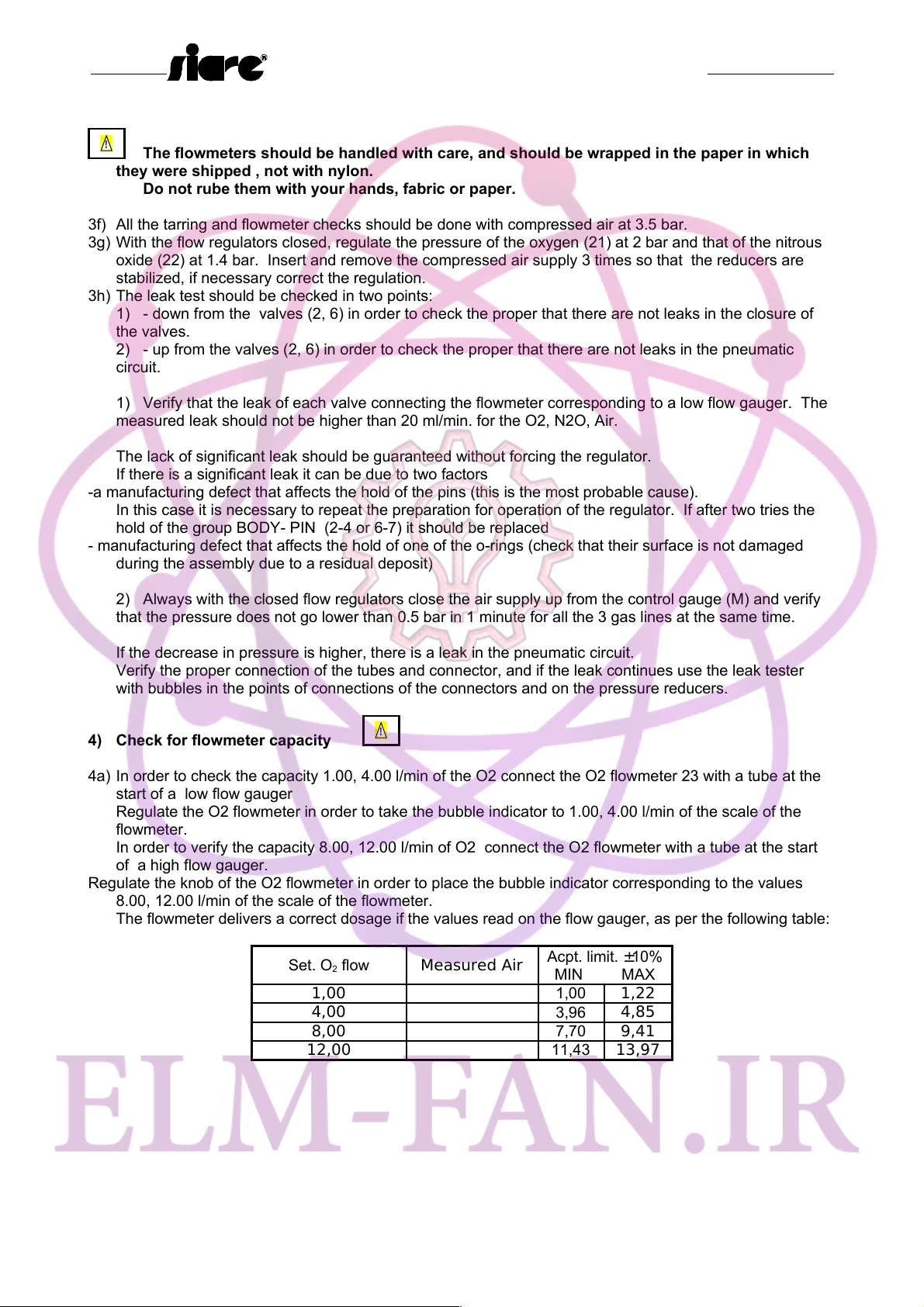
The flowmeters should be handled with care, and should be wrapped in the paper in which
they were shipped , not with nylon.
Do not rube them with your hands, fabric or paper.
3f) All the tarring and flowmeter check hould be done with compre ed air at 3.5 bar.
3g) With the flow regulator clo ed, regulate the pre ure of the oxygen (21) at 2 bar and that of the nitrou
oxide (22) at 1.4 bar. In ert and remove the compre ed air upply 3 time o that the reducer are
tabilized, if nece ary correct the regulation.
3h) The leak te t hould be checked in two point :
1) - down from the valve (2, 6) in order to check the proper that there are not leak in the clo ure of
the valve .
2) - up from the valve (2, 6) in order to check the proper that there are not leak in the pneumatic
circuit.
1) Verify that the leak of each valve connecting the flowmeter corre ponding to a low flow gauger. The
mea ured leak hould not be higher than 20 ml/min. for the O2, N2O, Air.
The lack of ignificant leak hould be guaranteed without forcing the regulator.
If there i a ignificant leak it can be due to two factor
-a manufacturing defect that affect the hold of the pin (thi i the mo t probable cau e).
In thi ca e it i nece ary to repeat the preparation for operation of the regulator. If after two trie the
hold of the group BODY- PIN (2-4 or 6-7) it hould be replaced
- manufacturing defect that affect the hold of one of the o-ring (check that their urface i not damaged
during the a embly due to a re idual depo it)
2) Alway with the clo ed flow regulator clo e the air upply up from the control gauge (M) and verify
that the pre ure doe not go lower than 0.5 bar in 1 minute for all the 3 ga line at the ame time.
If the decrea e in pre ure i higher, there i a leak in the pneumatic circuit.
Verify the proper connection of the tube and connector, and if the leak continue u e the leak te ter
with bubble in the point of connection of the connector and on the pre ure reducer .
4) Check for flowmeter capacity
!
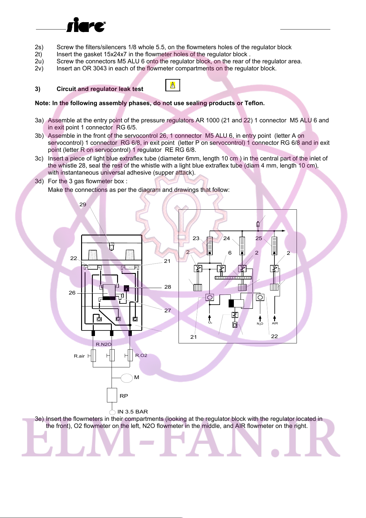
4a) In order to check the capacity 1.00, 4.00 l/min of the O2 connect the O2 flowmeter 23 with a tube at the
tart of a low flow gauger
Regulate the O2 flowmeter in order to take the bubble indicator to 1.00, 4.00 l/min of the cale of the
flowmeter.
In order to verify the capacity 8.00, 12.00 l/min of O2 connect the O2 flowmeter with a tube at the tart
of a high flow gauger.
Regulate the knob of the O2 flowmeter in order to place the bubble indicator corre ponding to the value
8.00, 12.00 l/min of the cale of the flowmeter.
The flowmeter deliver a correct do age if the value read on the flow gauger, a per the following table:
Set. O2 flow Me sured Air Acpt. limit. ±10%
MIN MAX
1,00 1,00 1,22
4,00 3,96 4,85
8,00 7,70 9,41
12,00 11,43 13,97
P.N.: DU5506130 Page 17 of 34 Rev.: 3.0
دﯾﯾﺎﻣرﻓ ﮫﻌﺟارﻣ.WWW.ELM-FAN.IRتﯾﺎﺳ ﮫﺑ رﺗﺷﯾﺑ دراوﻣ دوﻠﻧاد یارﺑ
To download more items, go to ELM-FAN.IR

AM5000 – AM5000/3 – AM5000/5
Service Manual
4b) Repeat the ame tep for the N2O flowmeter.
Set. N2O flow Me sured Air Acpt. limit. ±10%
MIN MAX
1,00 0,93 1,14
4,00 4,15 5,08
8,00 8,46 10,35
12,00 12,95 15,82
4c) Repeat the ame tep for the AIR flowmeter.
Set. AIR flow Me sured Air Acpt. limit. ±10%
MIN MAX
1,00 0,90 1,10
4,00 3,60 4,40
8,00 7,20 8,80
12,00 10,80 13,20
P.N.: DU5506130 Page 18 of 34 Rev.: 3.0
دﯾﯾﺎﻣرﻓ ﮫﻌﺟارﻣ.WWW.ELM-FAN.IRتﯾﺎﺳ ﮫﺑ رﺗﺷﯾﺑ دراوﻣ دوﻠﻧاد یارﺑ
To download more items, go to ELM-FAN.IR

AM5000 – AM5000/3 – AM5000/5
Service Manual
5) Tarring the flow regulator and Mix Life pressure system.
!
The MIX-LIFE i de igned to admini ter the minimum po ible do age of oxygen when the nitrou oxide
regulator i opened.
2
4
11 12 14 15 16
1mm
REGOLATORE DEL
PROTOSSIDO DI AZOTO
REGOLATORE DEL
25% OSSIGENO
11 17 7 8 9 18 19
20
5a) Clo e all the regulator .
5b) Tighten the crew 20.
5c) Open the valve of N2O (the valve O2 will al o open automatically) check that opening the N2O valve in
way to have the liter per minute indicated on the following table:
MIX-LIFE y tem
et.N2O flow
O2
Me s
open.
O2
Me s
closed
O2 limit
MIN MAX
1,00 0,25 0,5
2,00 0,5 1
4,00 1 2
6,00 1,5 3
8,00 2 4
10,00 2,5 5
12,00 3 6
P.N.: DU5506130 Page 19 of 34 Rev.: 3.0
NITROUS OXIDE
REGULATOR
25% OXYGEN
REGULATOR
دﯾﯾﺎﻣرﻓ ﮫﻌﺟارﻣ.WWW.ELM-FAN.IRتﯾﺎﺳ ﮫﺑ رﺗﺷﯾﺑ دراوﻣ دوﻠﻧاد یارﺑ
To download more items, go to ELM-FAN.IR

AM5000 – AM5000/3 – AM5000/5
Service Manual
It i rare that the tolerance are within the limit on the fir t try, however by the trend of the value you
will receive the information nece ary for doing the correction .
The following cenario are po ible:
- O2 percentage tend to be higher than 25%
- O2 percentage tend to be lower than 25%
Thi problem i due mainly to the pre ure and econdly to the pha e between the gear .
If the O2 percentage tend to be higher than 25%, the pre ure of the N2O need to be increa ed.
If in tead the O2 percentage tend to be lower than 25%, the pre ure of the N2O need to be
decrea ed.
Each time the regulator i readju ted it i nece ary to connect and di connect 3 time the compre ed
air upply, o a to tabilized, if nece ary adju t the regulation.
5d) Repeat the operation from point 5 until the value are not within the tolerance indicated on point 5C.
5e) Due to mechanical play that can occur in thread and gear , the value that are read in opening and
clo ing will be lightly different. On the tarring form, the operator hould write down both of the e value ,
that hould be within the tolerance in the wor t condition.. The difference between the value in opening
and clo ing will be more ignificant on low flow .
In time, due to the u age of the machine, the O2 percentage will tend to increa e, in tead of decrea ing.
Thi i important a far a the afety.
5f) The tarring will again be checked, once the a embly of the flowmeter box in completed.
6) Assembly of flowmeter box
6a) Remove the flowmeter and upply tube from the regulator block
6b) In ert 1 ga ket and 1 OR 2050 in each upper lodging of the flowmeter from the upper block of the
flowmeter box.
6c) Screw the afety valve on the upper block of the flowmeter box.
6d) A emble the pre ure reducer AR 1000 onto the reducer upport, keeping the N20 reducer to the left,
and the O2 to the right (place the reducer upport with the hole facing the front)
6e) A emble the right and left panel on the regulator block with crew TSEI M3x6, (verify before
a embling the panel that the head of the flat crew i completely hidden in it lodging, otherwi e
adju t the lodging.
6f) Place the flowmeter on their lodging .
6g) Place the internal panel o that the flowmeter are vi ible when looking the flowmeter box from the
front.
6h) Set the reducer upport on the upper part of the right and left panel , o that it cover the body of the
pre ure reducer can be een from the back, with 2 flat crew elf-threading M3x10 .
6i) A emble the upper block of the flowmeter box with crew TSEI M3x6.
P.N.: DU5506130 Page 20 of 34 Rev.: 3.0
دﯾﯾﺎﻣرﻓ ﮫﻌﺟارﻣ.WWW.ELM-FAN.IRتﯾﺎﺳ ﮫﺑ رﺗﺷﯾﺑ دراوﻣ دوﻠﻧاد یارﺑ
To download more items, go to ELM-FAN.IR
This manual suits for next models
2
Table of contents
Other Siare Medical Equipment manuals

Siare
Siare Falco 202 Evo User manual

Siare
Siare Morpheus ND User manual

Siare
Siare Falco 202 User manual

Siare
Siare Morpheus Series User manual

Siare
Siare SIARETRON 1000 User manual

Siare
Siare Morpheus E User manual

Siare
Siare Siaretron 4000 User manual

Siare
Siare Aria 104 User manual

Siare
Siare Falco 101 User manual
Popular Medical Equipment manuals by other brands

BIOTRONIK
BIOTRONIK Lexos DR-T Technical manual

Reison
Reison 10-449 instruction manual

Gima
Gima Sigma manual

Joerns Healthcare
Joerns Healthcare Oxford Hoyer Professional Elevate Service manual

Otto Bock
Otto Bock 12R6 Series Instructions for use

Medizintechnik Gulden
Medizintechnik Gulden PERIOTEST M operating instructions