Siare Siaretron 4000 User manual

Siaretron 4000
ICU Ventilator
Turbine-driven ventilation
Service Manual


GENERAL INFORMATION
The information contained in this manual are the exclusive property of
SIARE ENGINEERING INTERNATIONAL GROUP s.r.l. and may not be
reproduced in any way without authorisation. SIARE ENGINEERING
INTERNATIONAL GROUP s.r.l. reserves the right to modify or replace this
manual at any time without prior notice.
It is however recommended that you make sure you have the most recent
version of the manual. In the event of doubt, contact SIARE ENGINEERING
INTERNATIONAL GROUP s.r.l. (see the address on page IX). The
information contained in the present Service Manual can be considered
correct, but do not exclude professional knowledge by the user of the
equipment.
The operation and maintenance of Siaretron 4000 ventilator must be
entrusted to qualified technical personnel only. The responsibility of SIARE
ENGINEERING INTERNATIONAL GROUP s.r.l. concerning the Siaretron
4000 ventilator and its use is limited to what is indicated in the guarantee
supplied with the equipment.
The contents of this manual do not in any way limit the right of SIARE
ENGINEERING INTERNATIONAL GROUP s.r.l. to revise, change or modify
without prior notice the equipment (including the relative software) described
herein.
Unless otherwise specifically agreed in writing, SIARE ENGINEERING
INTERNATIONAL GROUP s.r.l. is not obliged to supply such revisions,
changes or modifications to the owner or user of the equipment (including
the relative software) described herein.
The information contained in this manual refers to the versions of Siaretron
4000 ventilator produced or updated after December 2016. It is possible that
some information may not apply to previous versions. Contact SIARE
ENGINEERING INTERNATIONAL GROUP s.r.l. if you have any doubts.
Service Manual, version DU5065101-TB
Revision 1 - 02.12.2016.
Observations
SIARE ENGINEERING INTERNATIONAL GROUP s.r.l. wishes to thank you
for purchasing one of its products.
Any comment on the accuracy and usefulness of this Service Manual would
be very helpful in allowing us to guarantee current and future users of the
high quality level of our manuals. We would be grateful if you would send us
your comments (see address at page IX).
The SIARE trademark is used throughout this manual as an abbreviation for
the manufacturer: SIARE ENGINEERING INTERNATIONAL GROUP s.r.l.
Directive 93/42 EEC
Definitions
Three symbols are used in this Service Manual to indicate particularly
important information.
WARNING!
This indicates a condition of danger for the patient or for
the operator.
CAUTION
This indicates the possibility of danger to the equipment.
NOTE
This indicates information worthy of note, making the
operation of the Siaretron 4000 ventilator more efficient or
practical.

Warnings, cautions and notes
You are advised to carefully read the information given alongside the three
symbols shown on the previous page, since it contains considerations on
the safety, the special requirements for the use Siaretron lung ventilator and
the relative safety regulations.
•In order to understand how the Siaretron lung ventilator works and how
to use it correctly to ensure patient and user safety, the
recommendations and instructions contained in this manual must be
read with care and understood.
•The User's Manual is an integral part of this manual; the technician
must retain a copy and understand the contents before performing
the operations described in the Service Manual.
•The lung ventilator must only be used for the purposes specified herein
and the safety of the equipment is therefore only guaranteed if it is used
in accordance with the instructions given in the User’s Manual.
•The materials used were carefully selected during the design stage after
specific checks, tests and comparative trials: these materials are also
constantly inspected during the production cycle to achieve the best
results in terms of reliability and safety for the patient and the operator.
Any part of circuit must therefore only be replaced with original spare
parts supplied or checked by SIARE.
•The lung ventilator must only be used by qualified personnel and only in
equipped and dedicated rooms, according to the regulations in force in
the country where the equipment is installed.
•To ensure correct technical assistance and avoid possible physical
damage to the patient, the maintenance schedule foreseen in the
User’s Manual must be respected; qualified personnel must only carry
out maintenance of the lung ventilator or authorised modifications to the
equipment. The user of this product is solely responsible for any
operating defect caused by improper use or interventions carried out by
third parties other than specialised SIARE personnel.
•For any repairs to lung ventilator (due to malfunctioning, defects or
failures), the user must contact SIARE or the authorised local Technical
Service Centre; it is advisable to specify the data on the identification
label (model, serial number, ……) when requesting intervention.
•SIARE recommends establishing a maintenance and service contract
with SIARE or the local authorised service dealer in order to guarantee
the scheduled maintenance required to operate the lung ventilator in a
safe and correct manner.
•To prevent the risk of fire, keep the lung ventilator and/or the oxygen
tubes of the equipment away from matches, lit cigarettes and
inflammable material, such as anaesthetic gases and/or sources of
heat.
•Do not connect the lung ventilator to the patient by flexible connectors,
and antistatic or conductive tubes to prevent patient burnings during the

use of high frequency surgical equipment, specially dangerous with
antistatic tubes. The use of flexible connectors, antistatic or conductive
tube is never permitted with Siaretron lung ventilator.
•Do not use worn and consumed tubes or tubes contaminated by
flammable substances like grease or oil to deliver oxygen; (fabrics, oil
and other fuels can easy ignite and they intensively burn in air with high
concentration of oxygen.
•In the event of fire or an unpleasant smell (e.g. a smell of burning), the
lung ventilator should immediately be disconnected from the electrical
power supply and from the battery (if fitted).
•When coming into contact with any component of the lung ventilator, the
hospital procedures for the handling of infected material should always
be respected.
•SIARE is aware that cleaning, sterilisation and disinfection procedures
vary considerably from one health structure to another. SIARE cannot
be held responsible for the efficacy of the cleaning and sterilisation
procedures, nor for the other procedures carried out while the patient is
being treated. As regards cleaning, sterilisation and disinfection of the
product components, it is therefore recommended that the regulations
currently in force in the country where the equipment is installed be
taken into consideration.
•The Siaretron lung ventilator was not designed as a total monitoring
device: some conditions of danger for the patients treated with vital
support equipment will not trigger any alarm.
•Before using the lung ventilator or any connected component, carefully
check that the equipment is functioning correctly; when needed, the
auto-diagnostic test must be performed as described in the User’s
Manual.
•Do not use pointed instruments, such as pencils, screwdrivers or the
like to make selections or settings as they could damage the surface
of the LCD panel.
•Check the lung ventilator periodically as described in the relative
“Maintenance” chapter and do not use it if it is faulty or malfunctioning.
Replace any broken, missing, obviously worn, deformed or
contaminated parts immediately, with spare parts supplied by SIARE.
•Do not connect external devices NOT manufactured or NOT authorized
by SIARE to the equipment (example: scavenging systems, patient
simulators, etc…..), and not described in the present service manual: in
case of need contact SIARE.
•The correct functioning of the lung ventilator can be impaired if original
SIARE spare parts and accessories are not used; the use of other
accessories is however allowed only if formally authorised by SIARE
in accordance with current safety regulations.

•SIARE assumes all foreseen legal liability if the lung ventilator is used
and periodically maintained according to the instructions contained in
this manual: the Technical Assistance Report, drawn up and signed by
the authorised SIARE technician, is proof of the completion of the
scheduled maintenance.
•Notwithstanding the Siaretron lung ventilator is equipped with a safety
valve which allows to the patient to breathe spontaneously the ambient
air even in case of gas supply failure, the auxiliary ventilation system
must be always promptly available; such a component is part of SIARE
ENGINEERING INTERNATIONAL GROUP s.r.l. products range.
WARNING !!
This equipment is not approved for operation in places where
there is any risk of explosion.
WARNING !!
Do not use the equipment in the presence of flammable
gases.
WARNING !!
The equipment cannot be used in the presence of explosive
gases.
WARNING !!
Before connecting the lung ventilator to other electrical
equipment not described in this manual, a request for
authorisation should be sent to Siare.
WARNING !!
Qualified staff must make the regulation of ventilation
parameters.
WARNING !!
An auxiliary ventilation system is suggested for the patients for
which the ventilator represents a life support.
WARNING !!
Means for independent ventilation shall be available (i.e.
manual resuscitation bag with mask) whenever the ventilator
is in use.

SIARE declines all civil and penal responsibility in the
following cases:
•If the lung ventilator is used in conditions and for purposes
not stated or described in this manual.
•If the lung ventilator is used by non-qualified personnel.
•If periodic maintenance as foreseen by this manual has
not been carried out correctly or has been skipped.
•If personnel not officially authorised by SIARE have
performed maintenance.
•If non-original SIARE spare parts or components not
checked by SIARE have been used.
•If the lung ventilator has been connected to equipment not
complying with the safety norms for the intended use.
•Direct or indirect damage to persons or things caused by
unauthorised technical intervention or by improper use of
the lung ventilator not in accordance with the instructions
contained in the users and service manual.
Year of manufacture
Check the identification data label of the equipment in the relative chapter.
Manufacturer
SIARE ENGINEERING INTERNATIONAL GROUP s.r.l.
Via Giulio Pastore, 18 - 40056
Località Crespellano, 40053 Valsamoggia (BO), ITALY
Tel.: +39 051 969802 - Fax: +39 051 969366

Electromagnetic Compatibility
The Siaretron lung ventilator is designed to operate in the specified
electromagnetic environment (see warning below).
The customer or the user of Siaretron lung ventilator should ensure that it is
used in such an electromagnetic environment.
The Siaretron lung ventilator complies with the EN 60601-1-2
regulations on Electromagnetic Compatibility of electro-medical
equipment. It is in any case highly recommended not to use the
Lung Ventilator adjacent to high-powered equipment or to units,
which emit strong electro-magnetic fields. Mobile phones,
cordless phones or other radio transmitters used in the vicinity
of the equipment could influence its operation. Whenever the
lung ventilator should be necessarily used nearby to such
equipment, it will be required to supervise its normal operation.
In general, as regards the regulations regarding
“electromagnetic emissions”, “electromagnetic immunity”
and “recommended separation distances between portable
and mobile RF equipment and the device”, always refer to
what is described in the Siaretron lung ventilator User’s
manual.
Requirements applicable to cables, transducers and other
accessories that could affect compliance with the requirements
of 6.1 and 6.2

Table of contents
GENERAL INFORMATION......................................................................................................................3
Observations.....................................................................................................................................4
Definitions .........................................................................................................................................4
Warnings, cautions and notes ..........................................................................................................5
Year of manufacture .........................................................................................................................9
Manufacturer.....................................................................................................................................9
Electromagnetic Compatibility ........................................................................................................10
Table of contents ............................................................................................................................11
1 INTRODUCTION .......................................................................................................................... 1-1
1.1 Intended use ......................................................................................................................... 1-1
1.2 Main features ........................................................................................................................ 1-2
1.3 Correct operation .................................................................................................................. 1-3
1.4 Service .................................................................................................................................. 1-4
2 DESCRIPTION ............................................................................................................................. 2-1
2.3 Lung ventilator front view...................................................................................................... 2-4
2.3.1 Electric connections side...........................................................................................................2-6
2.3.2 Gas supply side.........................................................................................................................2-8
2.4 12’’ LED display .................................................................................................................... 2-9
2.4.1 Keyboard with soft key and encoder knob...............................................................................2-10
2.4.2 Control keyboard description...................................................................................................2-10
2.5 IGU setting .......................................................................................................................... 2-12
2.6 Rear view ............................................................................................................................ 2-13
2.7 Product identification label.................................................................................................. 2-14
3 PROCEDURES: MAINTENANCE AND SERVICE...................................................................... 3-1
3.1 Introduction............................................................................................................................ 3-2
3.1.1 Necessary material....................................................................................................................3-2
3.2 Maintenance procedures....................................................................................................... 3-3
3.3 Daily maintenance................................................................................................................. 3-4
3.4 Weekly maintenance............................................................................................................. 3-5
3.5 Six-month maintenance ( 1000 hours )................................................................................. 3-6
3.5.1 Necessary equipment................................................................................................................3-6
3.5.2 Oxygen Coupling.......................................................................................................................3-8
3.5.3 Exhalation valve block.............................................................................................................3-10
3.5.4 EXP and INSP line rotary coupling..........................................................................................3-12
3.5.5 Air safety valve........................................................................................................................3-14
3.6 Annual maintenance ........................................................................................................... 3-15
3.6.1 Transducer O2 SIARE M20.....................................................................................................3-15
3.7 Final checks ........................................................................................................................ 3-17
3.8 Service procedures ............................................................................................................. 3-19
3.8.1 Opening the ventilator crankcase............................................................................................3-19
3.8.2 Replacing the batteries............................................................................................................3-20
3.8.3 Replacing the turbine module..................................................................................................3-21
3.9 Codes of supplied accessories ........................................................................................... 3-24
4 PROGRAMMING THE BOARDS................................................................................................. 4-1
4.1 Siaretron 4000....................................................................................................................... 4-2
4.1.1 Equipment needed ....................................................................................................................4-2
4.1.2 Programming the CPU board (cod. G3020204x).......................................................................4-3
4.2 How to change the MICRO - RENESAS device................................................................. 4-12
4.3 Programming summary....................................................................................................... 4-17

5 TESTING PROCEDURES............................................................................................................ 5-1
5.1 Necessary equipment ........................................................................................................... 5-2
5.2 Preliminary phase ................................................................................................................. 5-2
5.2.1 Connections ..............................................................................................................................5-2
5.2.2 Pre-testing phase ......................................................................................................................5-3
5.2.3 Setting up the simulator standard parameters...........................................................................5-3
5.3 Test procedure...................................................................................................................... 5-4
5.3.1 Aesthetics - Mechanical checks ...............................................................................................5-4
5.3.2 Labels / markings presence.......................................................................................................5-4
5.3.3 SW version................................................................................................................................5-4
5.3.4 SELF TEST...............................................................................................................................5-4
5.3.5 Patient circuit loss (TEST).........................................................................................................5-5
5.3.6 O2 Sensor calibration (TEST) ...................................................................................................5-5
5.3.7 O2 sensor check .......................................................................................................................5-5
5.3.8 Turbine calibration.....................................................................................................................5-6
5.3.9 Flow sensor calibration..............................................................................................................5-6
5.3.10 Trigger.......................................................................................................................................5-6
5.3.11 Respiratory rates check.............................................................................................................5-7
5.3.12 Low pressure circuit loss...........................................................................................................5-8
5.3.13 Power supply alarm...................................................................................................................5-8
5.3.14 Gas supply ................................................................................................................................5-8
5.3.15 INSP. HOLD Function ...............................................................................................................5-8
5.3.16 ESP. HOLD Function ................................................................................................................5-8
5.3.17 NEB. Function...........................................................................................................................5-9
5.3.18 100% O2 function......................................................................................................................5-9
5.3.19 FiO2 ..........................................................................................................................................5-9
5.3.20 APCV (Assisted Pressure Control Ventilation) operating mode ..............................................5-10
5.3.21 VC/VAC operating mode.........................................................................................................5-11
5.3.22 VC/VAC BABY operating mode...............................................................................................5-12
5.3.23 Low/high pressure alarm.........................................................................................................5-12
5.3.24 I:E ratio check..........................................................................................................................5-13
5.3.25 SIGH function..........................................................................................................................5-13
5.3.26 PEEP.......................................................................................................................................5-13
5.3.27 APCV-TV (Volume Targeted Assisted Pressure Control Ventilation)......................................5-14
5.3.28 PSV (Pressure Support Ventilation)........................................................................................5-15
5.3.29 PSV-TV (Volume Targeted Pressure Support Ventilation) operating mode ............................5-15
5.3.30 MAN Function..........................................................................................................................5-16
5.3.31 V-SIMV (Volume-Synchronised Intermittent Mandatory Ventilation).......................................5-16
5.3.32 P-SIMV (Pressure-Synchronised Intermittent Mandatory Ventilation).....................................5-17
5.3.33 CPAP (Continuous Positive Airway Pressure) operating mode...............................................5-18
5.3.34 APRV (Airway Pressure Release Ventilation) operating mode................................................5-18
5.3.35 Setting the default parameters ................................................................................................5-18
5.3.36 Gas Sensor .............................................................................................................................5-19
5.3.37 Measured respiratory parameters ...........................................................................................5-19
5.3.38 Additional respiratory parameters............................................................................................5-19
5.3.39 GRAPHICS - LOOPS..............................................................................................................5-19
5.3.40 TRENDS - EVENTS................................................................................................................5-19
5.3.41 Set Language..........................................................................................................................5-20
5.3.42 Electrical test sheet presence..................................................................................................5-20
5.3.43 CE certificate validity...............................................................................................................5-20
5.3.44 Operating hours.......................................................................................................................5-20
5.4 Test table............................................................................................................................. 5-21
6 CALIBRATION PROCEDURES................................................................................................... 6-1

6.1 Introduction............................................................................................................................ 6-2
6.1.1 Necessary equipment................................................................................................................6-3
6.2 Calibration programs............................................................................................................. 6-4
6.2.1 Turbine Characterization...........................................................................................................6-5
6.2.2 Expiratory flow sensors calibration............................................................................................6-8
6.2.3 VTEc........................................................................................................................................6-12
6.2.4 Neb. ( ON –OFF )...................................................................................................................6-13
6.2.5 IRMA / ISA - Trend and Events...............................................................................................6-14
6.2.6 Exit ..........................................................................................................................................6-15
6.3 PEEP Calibration ................................................................................................................ 6-16
6.4 Zeroing of “partial operating hours”..................................................................................... 6-18
6.5 Calibrations on board.......................................................................................................... 6-20
6.5.1 CPU / G3020204x Board.........................................................................................................6-20
6.6 Additional tests and checks................................................................................................. 6-21
6.7 Conclusions......................................................................................................................... 6-22
7 MAINTENANCE ........................................................................................................................... 7-1
7.1 Notes..................................................................................................................................... 7-2
7.2 Cleaning, disinfection and sterilization.................................................................................. 7-3
7.3 General indications ............................................................................................................... 7-4
7.3.1 Cleaning....................................................................................................................................7-4
7.3.2 Disinfection and sterilization......................................................................................................7-4
7.3.3 Disinfection by immersion (chemical)........................................................................................7-5
7.3.4 Cleaning, disinfection and sterilization table..............................................................................7-6
7.3.5 Periodic maintenance................................................................................................................7-9
7.3.6 Maintenance operations............................................................................................................7-9
7.3.7 Cleaning, disinfection and sterilization before use with another patient ..................................7-11
7.4 Repairs and spare parts...................................................................................................... 7-12
7.4.1 Annual kit for lung ventilator....................................................................................................7-12
7.5 Storage................................................................................................................................ 7-12
7.6 Repackaging and shipment................................................................................................. 7-12
7.7 Disposal............................................................................................................................... 7-13
8 DIAGRAMS .................................................................................................................................. 8-1
8.1 Boards blocks diagram.......................................................................................................... 8-2
8.1.1 Ventilator connections and supplies diagram............................................................................8-3
8.2 Electronic boards .................................................................................................................. 8-4
8.2.1 Description ................................................................................................................................8-4
8.2.2 CAN : Controller Area Network..................................................................................................8-4
8.2.3 Board CPU / G30202041...........................................................................................................8-5
8.3 Pneumatic diagrams ............................................................................................................. 8-7
8.3.1 Pneumatic diagram description.................................................................................................8-8
9 ANNEX ......................................................................................................................................... 9-1
9.1 Equipment............................................................................................................................. 9-2
9.1.1 Measuring instruments..............................................................................................................9-2
9.1.2 Equipment.................................................................................................................................9-2
9.2 Technical data sheet............................................................................................................. 9-3
9.3 Medical gas identification colours ......................................................................................... 9-4
9.4 Glossary................................................................................................................................ 9-5
9.5 Test procedure table ........................................................................................................... 9-11

1 INTRODUCTION
This Service Manual is intended to be used exclusively by SIARE
specialised staff or qualified technical staff, specifically authorised by
SIARE to use Siaretron 4000 lung ventilator for intensive care.
The specialist SIARE staff or qualified technical staff, formally authorised
by SIARE, must know the full content of this manual, before carrying out
the operations described below.
The SIARE authorised technician avails of suitable tools and spare parts
and is trained to work in compliance with product safety.
This Service Manual describes the Siaretron 4000 lung ventilator equipped with a turbine
and with a 12” TFT display (referred to from now on as: lung ventilator) along with its
principle of operation, by means of manufacturing, wiring and pneumatic diagrams. The
specialist SIARE staff or qualified technical staff, formally authorised by SIARE, must
know the full content, before carrying out the operations described below.
The SIARE authorised technician avails of suitable tools and spare parts and is trained to
work in compliance with product safety.
The correct and safe use for the patient and the operator of the equipment requires
knowledge of the recommendations and instructions outlined in this manual and the user
manual.
SIARE declines all liability for technical interventions carried out on the
equipment without formal authorisation from SIARE.
The User Manual is an integral part of this manual; the technician must
have a copy and know its content, before carrying out the operations
described in the Service Manual.
1.1 Intended use
The Siaretron 4000 system delivers controlled or spontaneous ventilations with a re-adjustable
level of end expiration positive pressure (PEEP), of the trigger sensitivity and oxygen
concentration.

Adult, paediatric and neonatal ventilation are available, thanks to an adjustable minimum Tidal
Volume from 2 ml to 3000 ml.
After the switching-on of the lung ventilator it is possible to choice the patient type (adult,
paediatric and neonatal) setting the relevant default parameters.

The lung ventilator is equipped with a flow and pressure trigger, also it includes the most
modern ventilation modes: volume controlled ventilation modalities VC/VAC, VC/VAC-
BABY, pressure controlled ventilation modalities APCV (BILEVEL ST), APCV-TV, SIMV by
Volume and by Pressure, Pressure supported modalities PSV (BILEVEL S), PSV-TV,
CPAP/PSV, SIGH, Non Invasive Ventilation (NIV APCV –NIV PSV), Drug Nebulizer and
Manual Ventilation (MAN).
In spontaneous ventilation mode, it ensures inspiratory flow up to 190 l/min, both with control
and support pressure.
The battery, in perfect conditions and fully charged, allows the lung ventilator to operate for at
least 90 minutes (without humidifier), allowing to power the lung ventilator in case of transport
within hospital facilities. It is possible to reach an autonomy of about 3 hours by the aid of an
auxiliary external battery (or battery pack).
This manual features the Siaretron 4000 ventilation system instructions for
use and servicing.
SIARE recommends careful reading of this manual and the relative
instructions before starting or servicing the lung ventilator.
For those who already have a basic knowledge on ventilators operation
and lung ventilation in general, the user interface is intuitive and a simple
consultation of this manual should be enough to assure an optimal use of
Siaretron 4000 ICU lung ventilator.
1.2 Main features
The Siaretron 4000 lung ventilator is composed of two main blocks: the trolley and the
ventilator block.
In turn, the lung ventilator block is divided in two parts: the upper part that includes a 12” TFT
colour monitor, the board for the elaboration of all data and information (CPU) that supervises
the operation and display of patient parameters.
To manage the pneumatic part and the turbine, the CPU board uses serial transmission
system by bus, type Controller Area Network (also known as CAN BUS) that allows it to check
and communicate with the electronic boards peripherals.
The CAN communication system was expressly designed to operate without any problem also
in environments highly disturbed by the presence of electromagnetic waves. The EMC
immunity level is further increased by using twisted pair type connection cables. The lower
part of the lung ventilator block includes the pneumatic control and all the fittings or
connections, both electrical and pneumatic, to the outside.
In this area are also mounted the back-up batteries for use in case of power supply absence
and the board for battery charge management.
The Siaretron 4000 foresees the possibility to upgrade the software for implementing
advanced ventilation modalities and functionalities.
The lung ventilator block can be used as a stand-alone part being separable from the trolley,
by positioning it on a flat surface.
1.3 Correct operation
For proper and full lung ventilator operation, you should make sure that:
•the lung ventilator is connected to the air and oxygen inlets of the cylinders or of the
medical gas distribution system; the compressed air can also be provided by the medical
air compressor (optional);
•the lung ventilator is properly connected to the patient circuit;
•the lung ventilator is connected to a mains socket that has the same voltage as the one
specified on the machine identification plate;
•all accessories and devices, necessary for lung ventilator operation, are properly
connected.
The connection with main power supply, as well as connections with medical gas
distribution system must be effected according to the indications contained in the
present user’s manual (see chapter 2).
The Siaretron 4000 lung ventilator doesn’t require any high pressure air supply as
it is equipped with an internal turbine.
The lung ventilator incorporate a series of sensors for continuous patient monitoring, the most
important of which are:
•the flow sensors on the expiratory / inspiratory lines, are used to measure the expiratory /
inspiratory volumes of the patient;
•the pressure sensors, used to control the pressure of the airways or of the medical gases;
•the oxygen sensor, used to measure the concentration of oxygen in the gas inspired by
the patient.
Before using the lung ventilator, the clinician should check the
operation of all these sensors in order to avoid any incorrect
assessments of patient's condition.
WARNING !!
Before using the lung ventilator on a patient it is necessary to perform
a series of preliminary checking to verify the correct operation of the
equipment.
The preliminary checking has the aim to verify the correct connections
and functionalities of the lung ventilator and all its parts.

For its employ the Siaretron 4000 lung ventilator has been designed and
made to guarantee full quality of the product and its components, in
order to ensure the maximum reliability of the lung ventilator for the
patient and user safety.
To ensure the best performance of the lung ventilator periodic
maintenance of the unit by qualified technical personnel is
recommended. For further information, contact SIARE Engineering
International Group s.r.l..
SIARE Engineering International Group s.r.l. recommends careful
reading of this manual and the relative labels before operating the lung
ventilator or carrying out any maintenance.
1.4 Service
To ensure regular functioning of Siaretron 4000 intensive care lung ventilator (equipped with a
turbine and with a 12” TFT display), adequately carry out all necessary interventions for the
procedures and protocols in force in the individual structures.
The following chapters cover the following topics.
•Ventilator description
•Service procedures
•Boards programming
•Test procedures
•Calibration procedures
•Maintenance and Service
•Equipment
•Wiring diagrams
•Annexes ( technical data sheet, pneumatic circuit, …… )
2 DESCRIPTION
This chapter describes the Siaretron 4000 lung ventilator equipped with a turbine and with a
12” TFT display; the main parts and modules of whose it is composed are specially
considered.
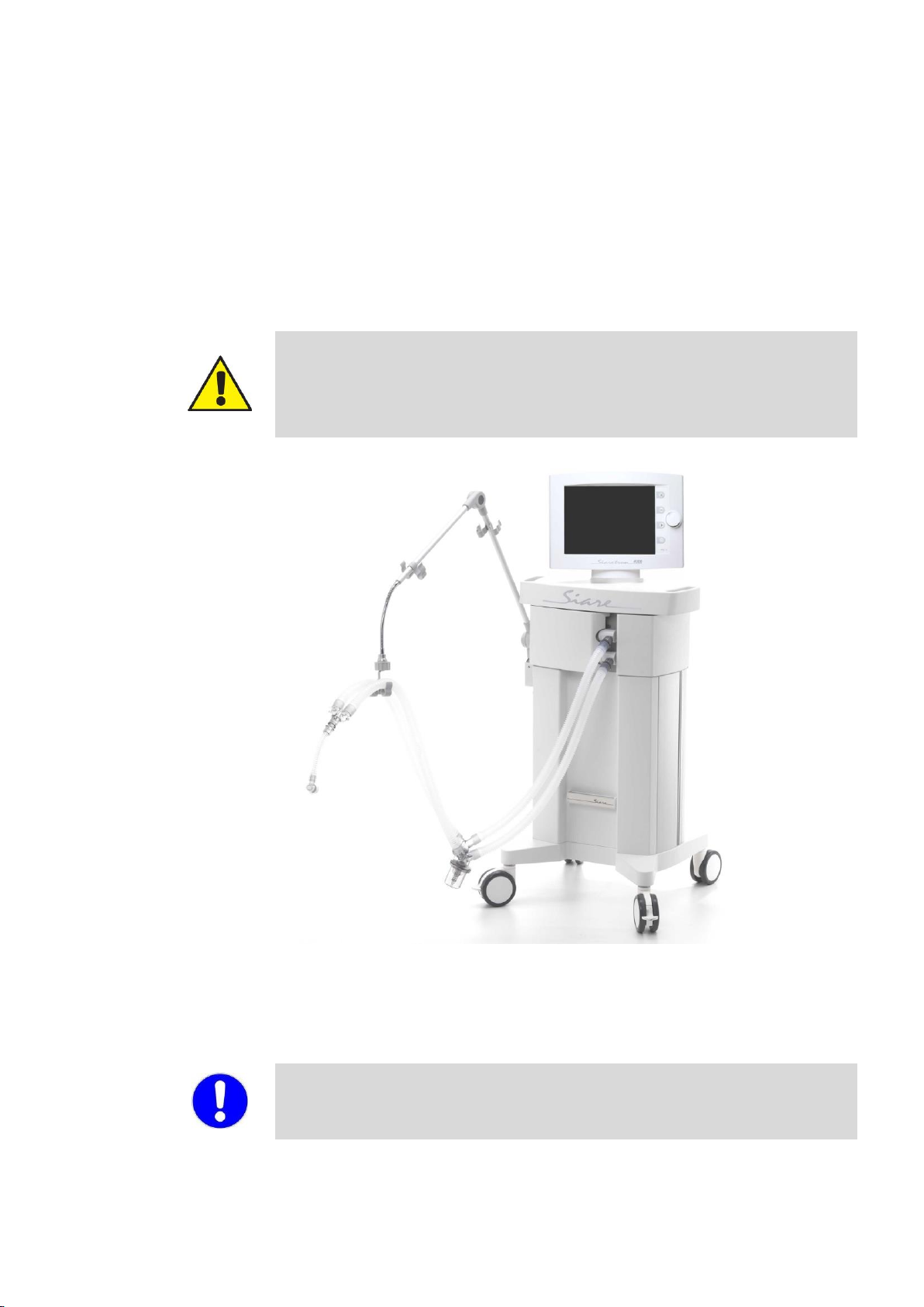
2.1 Overall view
WARNING!!
All the pictures and the examples shown in the present chapter have the mere
purpose of being an example and they do not make any reference to real clinical
cases.
Siaretron 4000 lung ventilator, available models:
•code 960402 turbine-driven : Adults, Paediatric and Neonatal (optional) patients
The picture is exclusively an example and shows a possible configuration of the
Siaretron 4000 lung ventilator (hereinafter called lung ventilator).
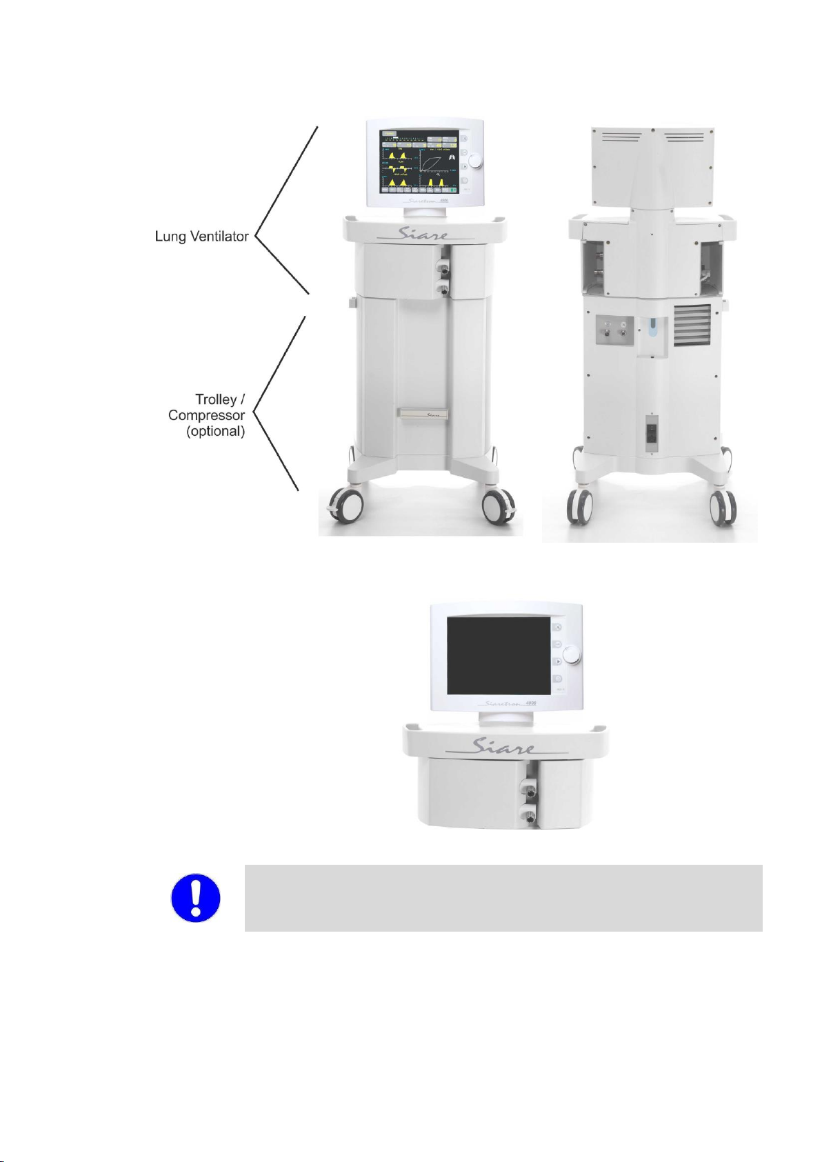
The ventilator block can be used as a stand-alone part being detachable from the
trolley, by positioning it on a flat surface.
Other manuals for Siaretron 4000
1
Table of contents
Other Siare Medical Equipment manuals

Siare
Siare Morpheus E User manual

Siare
Siare Falco 202 User manual

Siare
Siare Falco 202 Evo User manual

Siare
Siare Aria 104 User manual

Siare
Siare Morpheus ND User manual

Siare
Siare SIARETRON 1000 User manual

Siare
Siare Morpheus Series User manual

Siare
Siare AM5000 User manual

Siare
Siare Falco 101 User manual
Popular Medical Equipment manuals by other brands


Getinge
Getinge Arjohuntleigh Nimbus 3 Professional Instructions for use

Mettler Electronics
Mettler Electronics Sonicator 730 Maintenance manual

Pressalit Care
Pressalit Care R1100 Mounting instruction

Denas MS
Denas MS DENAS-T operating manual

bort medical
bort medical ActiveColor quick guide

AccuVein
AccuVein AV400 user manual


