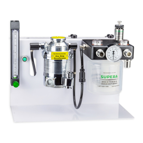
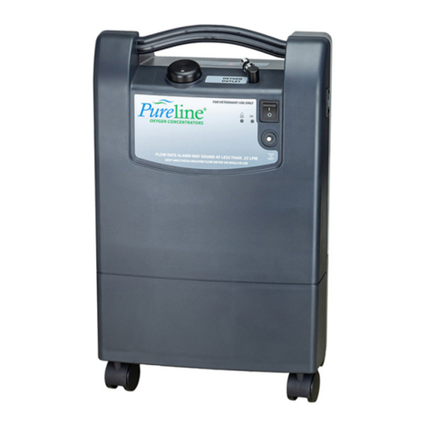
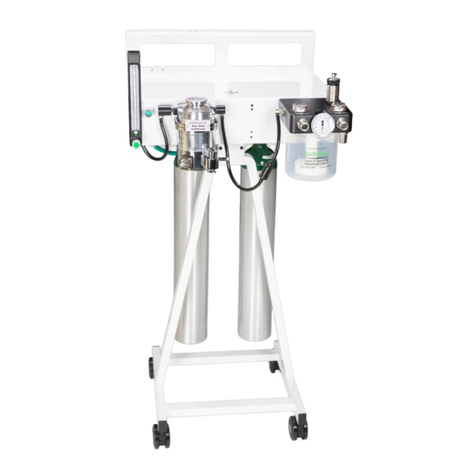
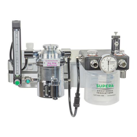
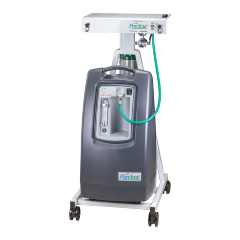
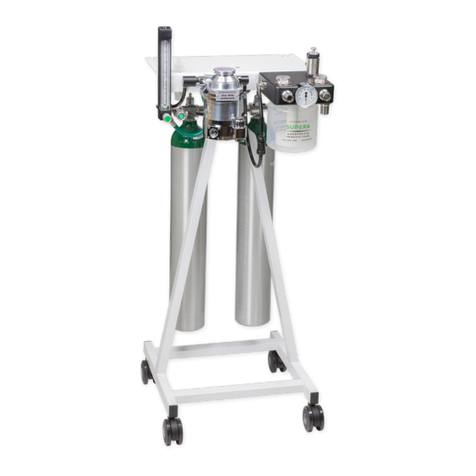
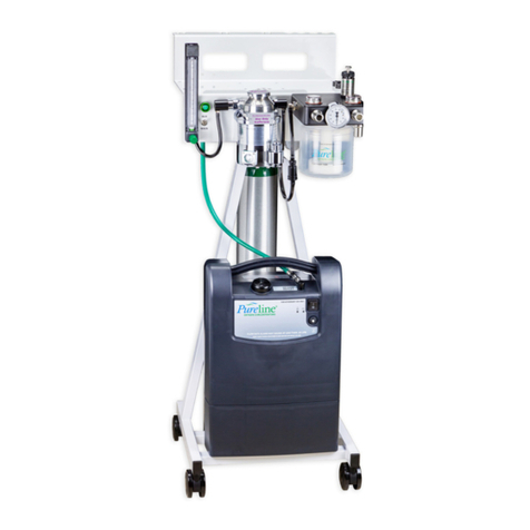
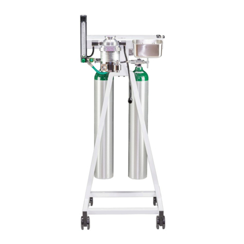
Supera Pureline OC6000 User manual

OC6000
Operators
Manual
Supera , LLC Copyright 2019
OXYGEN CONCENTRATORS
For Veterinary Use Only


Examination and Preparation for Use
We are delighted to have you as a Supera Anesthesia Innovations customer and want
you to be completely satised with your purchase. Please inspect the contents of your
order to see if everything is as you expected. Should anything not be exactly right or
if anything was damaged in shipping, please contact your sales representative right
away for help.
Our goal is to make your new machine as easy to use and care for as possible.
This device is meant to be operated under the normal surveillance and control of a
veterinarian trained in its use. However, you need to know more about this device than
just how to operate it.
Please read this manual in its entirety before using the machine.
If you have any comments or questions, we welcome the opportunity to address them.
Please contact us directly at 877–620–1500.
Thank you!
Brian Lawson
President,
Supera Anesthesia Innovations
Proudly Designed and
Made In Oregon, USA


Machine Assembly
3. Assemble the top assembly with the frame by installing the 1/4-20 X 1 3/4” long
screws and washers provided.
4. Tighten the screws with the 3/16”allen wrench provided VERY tightly.
1. Carefully unpack the top assembly and frame
from the box
2. Align the top to the frame as shown.
NOTE: The frame base has two cross bars with
holes in them for mounting the concentrator. That
is the front of the frame.
*See next page for fastening to frame
* NOTE: THIS REQUIRES TWO PEOPLE TO SAFELY ASSEMBLY *

1. Remove the oxygen concentrator from the box and guide the 4 threaded post
into the frame
2. Install and tighten the nuts.
DO NOT OVER TIGHTEN THE NUTS, SNUG FIT IS ALL THAT IS NEEDED

Attach the green hose from
the OC6000 top to the
threaded tting.
* DO NOT OVER TIGHTEN*
Oxygen Setup
Attach the green hose from
your anesthesia machine to
the DISS tting.

Auxiliary & Main Oxygen Switch
MAIN Switch Position
With the switch in the “MAIN”position
the supply of oxygen to the anesthesia
machine comes directly from the oxygen
concentrator.
NOTE: It does not ll the “E” tank.
AUXILARY Switch Position
With the switch in the “AUX”position, the supply of oxygen to the anesthesia machine comes
from “E” tank on the back of the machine or another source using the “E” tank adapter (p/n
OC6050)
To use the “E” tank as a souce for oxygen or to ush the machine, it must be turned on by
rotating the valve on top of the tank counter-clockwise SLOWLY to open.
NOTE: The “E” tank must be lled (about 2100 psi) by your local oxygen supply company.
The concentrator does NOT ll the tank.

USER'S GUIDE
OC4000
OXYGEN CONCENTRATOR
FOR VETERINARY USE ONLY
: ON (power switched on)
: OFF (power switched o)
: Class II protection
: Do not expose to open ames
: Do not use oil or grease
: Technical information
: Consult the accompanying documents
: Keep in the vertical position
: Fragile - handle with care
: Oxygen concentration warning light
GLOSSARY OF SYMBOLS
I
O
OXYGEN CONCENTRATORS

.
The WARNINGS below indicate a potential
hazardous situation. If conditions are not
avoided a situation could occur that results
in serious injury or death.
• Oxygen is not a ammable gas, but it
accelerates the combustion of materials. Do
not use in explosive atmosphere. To avoid risk
of re and explosion the concentrator should
be kept away from Flames, Heat sources,
Incandescent sources, Smoking Materials,
Matches, Oil, Grease, Solvents, Aerosols, etc.
• Use of other accessories not described in this
User's Guide are not recommended.
•
• No modication to the equipment is allowed.
• Device must have power to operate. In the
event of power loss and for continued op-
eration a backup source is recommended.
• DO NOT disassemble due to danger of
electrical shock. Refer servicing to quali-
ed service personnel.
GENERAL SAFETY GUIDELINES
Only persons who have read and understood this entire manual
should be allowed to operate the O2 concentrator
The CAUTIONS below indicate a potentially
hazardous situation. If conditions are not
avoided a situation could occur that results
in property damage or minor injury or both.
• Use the power cord provided, and check that
the electrical characteristics of the power
socket used match those indicated on the
manufacturer’s plate on the rear panel of
the device.
• We recommend against the use of extension
cords and adapters, as they are potential
sources of sparks and re.
• The concentrator has an audible alarm to
warn the user of problems. In order that the
alarm may be heard, the maximum distance
that the user can move away from it must
be determined to suit the surrounding noise
level.
• Do not use in a specifically magnetic
environment (MRI, X-ray, etc.). May cause
device malfunction.
• This unit may be equipped with a polarized
plug. That is one blade wider than the other.
If it does not t into the outlet, reverse the
plug. If it still does not t, contact a qualied
electrician. Do not defeat this safety feature.

CONFORMITY WITH IEC60601-1 (2nd
Edition)
"The manufacturer, assembler, installer or
distributor are not considered to be responsible
themselves for the consequences on the safety,
reliability and characteristics of a device unless
the:
• Assembly, tting, extensions, adjustments,
modications or repairs have been performed
by persons authorized by the party in
question.
• Electrical installation of the corresponding
premises complies with local electrical
codes. (e.g. IEC / NEC).
• Device is used in accordance with the
instructions for use.
If the replacement parts used for the periodic
servicing by an approved technician do not
comply with the manufacturer’s specications,
the manufacturer is not responsible in the event
of an accident.
1. UNPACKING and PACKAGING
The Oxygen Concentrator is packaged to
protect the device from damage while being
transported and stored. Check for damage to
the packaging. After device is removed from
the package inspect for damage. If damage
is detected please contact your equipment
provider. Operating environmental condi-
tion guidelines are discussed later in another
section of this User's Guide.
1.1 METHOD FOR WASTE DISPOSAL
All waste from the device (Patient Circut,
Filters, Etc.) must be disposed of using methods
appropriate to the civil authority of the location
where disposed.
2.0 METHOD FOR DISPOSING OF
DEVICE
This device has been supplied by an environ-
mentally aware manufacturer. A majority of the
parts in the device are recyclable.
Follow local governing ordinances and recy-
cling plans regarding disposal of the device or
components normally used in operation. Any
accessories not original to the device must be
disposed of in accordance with the individual
product markings for disposal.

2.1. Front panel (Fig. 2.1)
1 - I/O (ON/OFF) switch
2 - Indicator lights
3 - Oxygen product outlet
4 - Circuit breaker
5 - Pre-set ow meter (non-adjustable)

3.1 Turning on device
a. Plug the power cable into a power outlet (Fig.
3.3) of the correct voltage and frequency as
dened on the manufacturer's technical label (Fig
2.2).
b. Press the power switch (I/O) (item 1 in Fig.2.1)
to the ON position (I). The green indicator light
ashes until concentration is achieved.
IMPORTAINT!
TURN THE ANESTHESIA MACHINES
OXYGEN FLOW METER ON TO A
MINUMUM FLOW RATE OF 0.25 LPM
A “NO FLOW” ALARM MAY SOUND IF
THE FLOW METER ISN’T OPEN
3.2 Turning o device
At the end of the usage, press the I/O Switch to
place it in the O(OFF) position to stop the device.
The oxygen enriched air ow continues for ap-
proximately one minute after the device is stopped.
1. Filter / Silencer
2. Cabinet lter
3. Ventilation grill
Note: Shown with grate removed
Fig. 4.1
4. CLEANING - MAINTENANCE
Only the outside of the concentrator is to be
cleaned. Use a damp sponge or cloth with
water only.
Acetone, solvents or any other inammable
products must not be used.
Do not use abrasive powders.
FILTERS - IMPORTAINT!
Fine Filter (#1 g. 4.1)
and Cabinet Filter Cleaning (#2)
The cabinet lter (#2 Fig.4.1) must be cleaned
in warm water and household detergent weekly
or after approximately 100 hours of use. Dry
before reinstalling. More frequent cleaning is
recommended in dusty environments.
Cabinet lter: p/n OC4000-1
T h e n e i n t a k e lt e r s h o u ld b e r e p l a c e d a n n u a l l y
or every 2000 hours of use. More frequently
dusty /dirty environments.
Fine lter p/n OC4000-2

4.3. Maintenance
NO INTERNAL MAINTENANCE
IS REQUIRED OR SHOULD BE
PERFORMED.
OPENING THE CASE WILL
VOID THE WARRANTY.
5. USEFUL INFORMATION
5.1. Accessories and spare parts
The accessories used with the O2 concentrator
must:
• be oxygen compatible.
• be biocompatible.
The connectors, tubes must be designed for
oxygen usage.
5.2. Materials in direct or indirect contact
with the product output
Concentrator casing ................................ABS
Power Cord ........................................... PVC
Cabinet Air Filter ..............................Polyester
I/0 (On/O) switch................................Nylon
Casters....................................................Nylon
Oxygen product outlet ...................Aluminum
Printed labels.............................Polycarbonate
Pipe/Tubing..........................Aluminium,PVC,
polyurethane or silicone
5.3. Operating principle
The compressor sends ltered room air to a
solenoid valve, which allows compressed air to
pass to the column in production. The columns
contain a molecular sieve, whose function is to
adsorb the nitrogen and thus allow oxygen to pass.
The oxygen enriched product is then directed
through a pressure reducing valve continuing
to the oxygen product outlet tting.
During this time, the column which is being
"regenerated" is connected to the ambient air
and ow of oxygen enriched product is passed
through it (from the column "in production"). In
this way, when one column is in production, the
other is in a nitrogen desorption or "regenera-
tion" phase. The oxygen enriched product nally
passes through a nal product lter located prior
to the oxygen outlet tting.
5.4. Alarms - Safety devices - Indications
5.4.1. Alarms
• No voltage detection
In the event of a loss of mains power, an inter-
mittent audible alarm is activated and the green
light turns o. Test alarm by actuating the I/O
(ON/OFF) switch when the power cord is not
plugged into the wall outlet.

• Process fault
In the case of a process fault, a visible and au-
dible alarm is activated (continuous red light or
lighted alarm and audible alarm).
• Oxygen Concentration
If the oxygen concentration level falls below the
required range the red light comes on and the
green light goes out. After a 15 minute delay
the audible alarm will sound.
5.4.2. Safety devices
• Compressor motor
Thermal safety is ensured by a thermal switch
situated in the motor winding (145 ± 5 oC).
• Electrical protection
A 5 amp circuit breaker is incorporated into the
front cabinet of all models.
Class II devices with insulated casings (EN60601-
1 standard)
• Safety valve
This is tted on the compressor outlet and is
calibrated to 2.7 bar (40 psig).
5.4.3 Indicators
• The green indicator light (Fig.5.1) indicates
that power is applied to the device. When
rst turned on the indicator will ash until
correct oxygen concentration is achieved.
At that time the green indicator will remain
illuminated and the device is ready to provide
oxygen enriched air to the patient.
5.4.3 Indicators (continued)
• The red indicator warns of a process fault.
One event that can cause the red indicator
to be illuminated is low oxygen concentra-
tion. The low oxygen concentration red
indicator will light when oxygen concen-
tration falls below a predetermined set
point. Another event that will cause the
red indicator to light is a blocked oxygen
ow. In this case the green indicator and
red indicator will be illuminated simulta-
neously.

5. 5. OCSI (oxygen concentration status
indication module) function
5.5.1. Operating principle
The oxygen monitor (Item 2 Fig 2.1) is an
electronic module capable of checking the
eective oxygen concentration supplied by
the concentrator.
The oxygen monitor measures the concentra-
tion and activates an audible and visual alarm
if it falls below the alarm set point percentage.
(Refer to Section 5.4 for information on the
operation of the indicators and alarms for the
OCSI function)
(Values at 21oC and at one atmosphere pressure).
Maximum ow: 5 lpm.
The variation of the maximum ow does not
exceed ± 10 % of the indicated value when a
back pressure of 7 kPa (1 psig) is applied to
the output of the device. The maximum outlet
pressure is 50 kPa (7 psig).
5.5.4 Maintenance of the Device Alarms
No special maintenance is required. The alarm
set-point is factory set and the setting cannot be
adjusted. All models are set at 84%.
The equipment supplier veries that the device
is still operating correctly when the routine
checks are performed.
5.6. Technical characteristics
Dimensions:
LxWxH: 36 x 23 x 58.5 cm (14 x 9 x 23 in.)
Caster diameter: 3.8 cm (1.5 in.).
Weight: 14.5 kg. (32 lbs) varies by model.
Noise level conforms to ISO 8359 Standards.
Oxygen Concentration - USP93%
• at 2 l/min: >90%.
• at 5 l/min: 90%. (+6.5%/-3%)
(Fig. 5.1)
Red Indicator Green Indicator

PREVENTIVE MAINTENANCE
a. Wash cabinet lter weekly.
b. The ne intake lter should be replaced
annually or every 2000 hours of use. More
frequently dusty /dirty environments.
c. Check oxygen concentration every 15,000
hours or 3 years of operation to verify the
continuing OCSI function.
Use original parts only
Contact Supera Anesthesia Innovations
for additiional information
877-620-1500
Electrical power supply:
Rating: 115/230V 60Hz 230V 50Hz
Average Power: 330W(avg) 300 W(avg)
Protection Class: Class II Class II
Mains Protection: 5A 5A
Filters:
At the rear of the device: a cabinet air lter.
At the compressor input: an inlet air lter, 5 µm,
located behind the cabinet air lter.
Air circulation
A tubeaxial fan cools the compressor compart-
ment.
Environmental limit conditions
The performances of the device (especially the
oxygen concentration) are quoted at 21oC (70oF)
and one atmosphere. They may change with
temperature and altitude.
• The device must be stored, transported and
used in the vertical position only.
• Ambient temperature of between 5oC and
40oC (40oF to 104oF) operation.
• Storage temperature from -20oC to 60oC
(-4oF to 140oF).
• Relative humidity of between 15% and 95%
operation and storage, both non-condensing.
• Altitude(21oC): Up to 2,286m (7,500ft)
without degradation; Consult your equip-
ment provider for further information re-
garding 2,286m to 4000m (7500 to 13000
ft)
• Complies with EN60601-1 standard; spil-
ling a glass of water.
5.7. Standards
EN 60601-1[UL60601-1:2003],
CAN/CSA-C22.2 No.601.1-M90 w/A1&A2:
Electrical Safety- Medical Devices.
EN60601-1-2:2001
Electromagnetic Compatibility

5.8. Troubleshooting.
Solutions
Check the cable connection.
Check the circuit breaker (5) on the
front of the unit; Reset if necessary.
Contact your equipment supplier.
Backup capacitor has discharged
operate unit for approximately 10
minutes and retest
Contact your equipment supplier.
Stop the device by pressing the
I/O (ON/OFF) button and contact
your equipment supplier.
Stop the device and contact your
equipment supplier.
Clean cabinet lter. Restart.
Clear blockage. Restart
Reset circuit breaker. If the device
does not start, contact your equip-
ment supplier.
Power cord is not correctly
plugged into the wall outlet.
Power failure.
Oxygen concentration is too
low.
Capacitor is not charged
Internal electrical fault.
Faulty indicator.
Pneumatic connection broken or
other pressure problem.
Internal electrical fault.
Pneumatic circuit fault.
Dirty Filters, blockage
Fan is not working.
Observations
The I/O (ON/OFF) button is in the "I"
(ON) position but the device does not
operate.
The audible alarm sounds intermit-
tently.
Red light remains lighted.
The alarm test does not work.
See 5.4.1.
The compressor operates and the
I/O (ON/OFF) button is in the "I"
(ON) position but the green indicator
is not lighted.
The I/O (ON/OFF) button is in the "I"
(ON) position but there is no ow.
The audible alarm sounds continu-
ously.
The I/O (ON/OFF) button is in the
"I" (ON) position, the compressor is
operating and there is a ow but the
audible alarm sounds continuously.
The compressor stops in mid-cycle,
then starts again after a few minutes.
Maintenance Items
Cabinet Air Filter: Ref: OC4000-1; Wash weekly; Replace as needed.
Inlet Air Filter: Ref: OC4000-2; Replace minimum every 2000 hours
(depending on environment)
Possible Causes


This manual suits for next models
1
Table of contents
Other Supera Medical Equipment manuals
Popular Medical Equipment manuals by other brands

Enovate Medical
Enovate Medical ENCORE LITE quick start guide

Stealth Products
Stealth Products SUS9 Swing Away Series user manual

Winncare
Winncare DUO Series manual

Beurer medical
Beurer medical IPO 61 Instructions for use

VELA Medical
VELA Medical Latin 100 user manual

OAKWORKS
OAKWORKS Clodagh Leo user manual