manuals.online logo
Brands
  1. Home
  2. •
  3. Brands
  4. •
  5. Siccom
  6. •
  7. Water Pump
  8. •
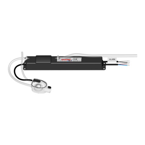
  9. Siccom mini FLOWATCH 1 EVO User manual

Siccom mini FLOWATCH 1 EVO User manual

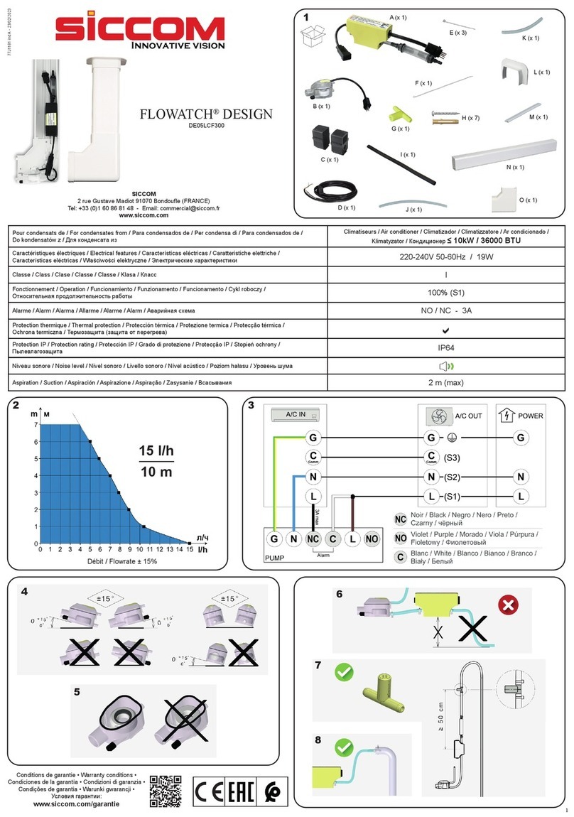
mini FLOWATCH®1 EVO
DE05LCD600
SICCOM
2 rue Gustave Madiot 91070 Bondoue (FRANCE)
Tel: +33 (0)1 60 86 81 48 - Email: [email protected]
www.siccom.com
77J1170 ind A - 16/09/2020
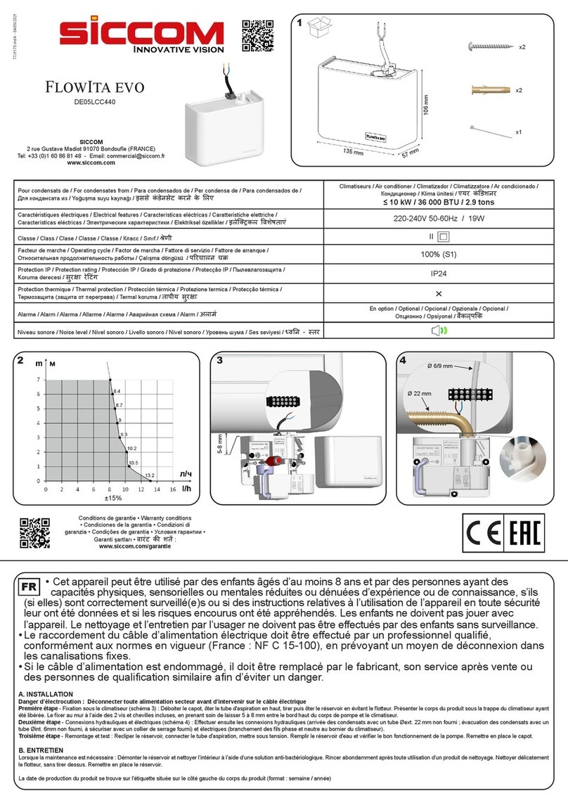
Pour condensats de / For condensates from / Para condensados de / Per condensa de / Для конденсата из Climatiseurs / Air conditioner / Climatizador / Climatizzatore / Кондиционер
< 10kW / 36000BTU
Caractéristiques électriques / Electrical features / Características eléctricas / Caratteristiche elettriche /
Электрические характеристики 220-240V 50-60Hz / 19W
Classe / Class / Clase / Classe / Класс II
Facteur de marche / Operating cycle / Factor de marcha / Fattore di servizio /
Относительная продолжительность работы 100% (S1)
Alarme / Alarm / Alarma / Allarme / Аварийная схема NC - 3A max resistive
Protection thermique / Thermal protection / Protección térmica / Protezione termica / Термозащита (защита от
перегрева) a
Protection IP / Protection rating / Protección IP / Grado di protezione / Пылевлагозащита IP64
5
4
1
2
3
6 7
88
30
45
75 38
36
C (x1)
A (x1)
B (x1)
D (x1)
1.5m E (x1)
F (x3)
G (x1)
Conditions de garantie • Warranty conditions
• Condiciones de la garantía • Condizioni di
garanzia • Условия гарантии :
www.siccom.com/garantie
B
E
F
G
C
A
D
>0m
• Cet appareil peut être utilisé par des enfants
âgés d’au moins 8 ans et par des personnes ayant
des capacités physiques, sensorielles ou mentales
réduites ou dénuées d’expérience ou de connaissance,
s’ils (si elles) sont correctement surveillé(e)s ou si des
instructions relatives à l’utilisation de l’appareil en toute
sécurité leur ont été données et si les risques encourus
ont été appréhendés. Les enfants ne doivent pas jouer
avec l’appareil. Le nettoyage et l’entretien par l’usager
ne doivent pas être effectués par des enfants sans
surveillance.
• Le raccordement du câble d’alimentation électrique
doit être effectué par un professionnel qualié,
conformément aux normes en vigueur, en prévoyant
un moyen de déconnexion dans les canalisations
xes.
• Le câble d’alimentation ne peut pas être remplacé.
Si le câble est endommagé, il convient de mettre
l’appareil au rebut.
A. BRANCHEMENT ELECTRIQUE / ALARME
1. Alimentation électrique de la pompe
Déconnecter toute alimentation secteur pendant l’installation.
2. Branchement de l’alarme
La pompe dispose d’un contact de sécurité normalement fermé (NC) permettant d’arrêter l’unité
intérieure de climatisation en cas de risque de débordement des condensats (pensez à vérier les
spécications du climatiseur). Respectez le schéma 5 pour le branchement de l’alarme.
B. INSTALLATION DU BLOC POMPE
Le bloc pompe (A) peut être xé dans le climatiseur, dans une goulotte ou en faux plafond. Un espace
libre de doit être préservé autour du bloc pompe pour permettre son refroidissement en cas de marche
prolongée. Le bloc pompe ne doit pas être couvert (ni isolant, ni mousse expansive,etc.).
Le tube de refoulement (non fourni) doit avoir un diamètre 6x9mm pour être xé sur le raccord de sortie.
Utiliser un collier de serrage (fourni - F) an de xer durablement le tube de refoulement à la pompe.
Respecter le sens d’écoulement indiqué par la èche sur le bloc pompe.
Si la sortie du tube de refoulement de la pompe se situe à un niveau inférieur au bloc pompe, et
dans le but d’éviter un effet de siphonage (décharge négative, entrainant un bruit anormal et une
usure prématurée de la pompe), il est impératif de :
- soit raccorder la sortie du tube de refoulement à un tube de diamètre supérieur.
- soit installer le Stop Siphoning SICCOM (non fourni).
C. INSTALLATION DU BLOC DE DETECTION
Le bloc de détection (B) est alimenté en TRES BASSE TENSION par le bloc pompe. Il est impératif
d’utiliser le câble fourni. Un manchon coudé souple (fourni - C) permet de raccorder le bloc de détection
au bac du climatiseur. L’aspiration se fait par le tube souple de 1,5 mètre (fourni - D) ayant un diamètre
interne de 5 mm. Utiliser les 2 colliers de serrage (fournis - F) pour xer durablement ce tube souple au
niveau du bloc de détection et de la pompe. Raccorder le tube d’évent (fourni - E), diamètre interne 4
mm, longueur 150 mm.
Le bloc de détection doit être placé et xé en position horizontale - voir schéma 6 - au moyen de
l’adhésif double-face velcro (fourni - G).
Choisir le sens d’évacuation le mieux adapté à l’application, et obturer à l’aide du bouchon noir la sortie
d’évacuation inutilisée.
D. FONCTIONNEMENT ET ENTRETIEN
1. TEST DE FONCTIONNEMENT (recommandé)
Attention : Ne jamais faire fonctionner la pompe à sec plus des quelques secondes indispensables pour
la mise en service (risque de détérioration de la pompe)
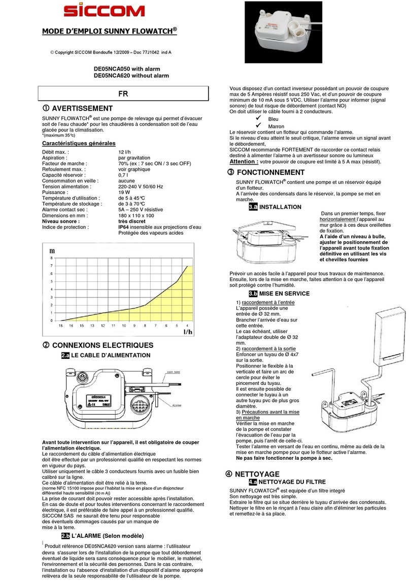
• Verser de l’eau dans le bac du climatiseur sans excès (NB le tube d’évent doit rester sec)
• Vérier la mise en marche de la pompe et constater l’évacuation de l’eau par la pompe, puis l’arrêt
de celle-ci.
• Tester l’alarme en versant de l’eau en continu, même au delà de la mise en marche pompe pour que
le otteur active l’alarme (otteur niveau haut).
2. ENTRETIEN
Toute intervention sur la pompe de relevage de condensats doit être effectuée hors tension.
Lorsque la maintenance est nécessaire : Enlever le couvercle du bloc de détection, le ltre et le
otteur. Nettoyer l’intérieur du réservoir ainsi que le otteur avec une solution eau + javel 5%. Rincer
abondamment après toute utilisation d’un produit de nettoyage. Assurez-vous que le joint du couvercle
est bien dans son logement. Assurez vous que le otteur est bien positionné (aimant vers le haut) - voir
schéma 7.
FR
• This appliance can be used by children from
8 years and above and people with reduced
physical, sensory or mental capabilities or lack of
experience and knowledge if they have been given
supervision or instruction concerning the use of the
appliance in a safe way and understand the hazards
involved. Children must not play with the appliance.
Cleaning and maintenance by the user must not be
performed by children without supervision.
• The connection of the power supply cable must be
carried out by a qualied professional, in accordance
with the standards in force, providing a means of
disconnection in the xed pipes.
• The power cable cannot be replaced. If the cable is
damaged, the unit should be discarded.
A. ELECTRIC / ALARM CONNECTION
1. Pump power supply
Disconnect power supply during installation.
2. Alarm connection
The pump has a normally closed (NC) safety contact to stop the indoor air conditioning unit if there is a
risk of condensate overow (remember to check the specications of the air conditioner). Follow gure
5 for the alarm connection.
B. PUMP UNIT INSTALLATION
The pump unit (A) can be mounted in the air conditioner, in a trunking or in a false ceiling. A free space
must be left around the pump unit to allow it to cool down in case of prolonged operation. The pump unit
must not be covered (no insulation, foam, etc.).
The discharge tube (not supplied) must have a diameter of 6x9mm to be xed on the outlet connection.
Use a hose clamp (supplied - F) to permanently x the discharge tube to the pump.
Observe the direction of ow indicated by the arrow on the pump unit.
If the end of the discharge tube is at a lower level than the pump unit, and in order to avoid a
siphoning effect (negative discharge, leading to abnormal noise and premature wear of the
pump), it is imperative to:
- connect the outlet of the discharge tube to a pipe with a larger diameter.
- or install the Stop Siphoning SICCOM (not supplied).
C. DETECTION UNIT INSTALLATION
The detection unit (B) is supplied with VERY LOW VOLTAGE by the pump unit. It is imperative to use
the supplied cable. A exible elbow sleeve (supplied - C) is used to connect the detection unit to the
air conditioner tank. Suction is made through the 1.5 metre exible tube (supplied - D) with an internal
diameter of 5 mm. Use the 2 clamps (supplied - F) to permanently x this exible tube to the detection
unit and the pump. Connect the vent tube (supplied - E), internal diameter 4 mm, length 150 mm.
The detection unit must be placed and xed in a horizontal position - see gure 6 - by means of the
double-sided Velcro adhesive (supplied - G).
Choose the most suitable discharge direction for the application and seal the unused discharge outlet
with the black plug.
D. OPERATION AND MAINTENANCE
1. OPERATING TEST (recommended)
Caution: Never run the pump dry for more than the few seconds required for commissioning (risk of
damage to the pump).
• Pour water into the air conditioner tray without excess (NB the vent tube must remain dry).
• Check that the pump is switched on and that the water is drained from the pump and then switched
off.
• Test the alarm by pouring water continuously, even after the pump is switched on so that the oat
activates the alarm (high level oat).
2. MAINTENANCE
Any work on the condensate pump must be carried out with the power off.
When maintenance is required: Remove the cover of the detection unit, the lter and the oat. Clean
the inside of the reservoir and the oat with a water + 5% bleach solution. Rinse thoroughly after using
any cleaning product. Make sure that the cover gasket is in its housing. Make sure that the oat is
correctly positioned (magnet upwards) - see diagram 7.
EN
• Este aparato puede ser utilizado por niños de
8 años o más y por personas con capacidades
físicas, sensoriales o mentales reducidas o sin
experiencia o conocimientos, si se les supervisa
adecuadamente o si se les han dado instrucciones
sobre cómo utilizar el aparato de forma segura y
si se comprenden los riesgos que conlleva. Los
niños no deben jugar con el aparato. La limpieza y
el mantenimiento por parte del usuario no debe ser
llevada a cabo por niños sin supervisión.
• La conexión del cable de alimentación debe ser
realizada por un profesional cualicado, de acuerdo
con las normas vigentes, proporcionando un medio
de desconexión en las tuberías jas.
• El cable de alimentación no puede ser reemplazado.
Si el cable está dañado, la unidad debe ser
desechada.
A. CONEXIÓN ELÉCTRICA / ALARMA
1. El suministro de energía de la bomba
Desconectar de toda alimentación eléctrica durante la instalación.
2. Conectando la alarma
La bomba tiene un contacto de seguridad normalmente cerrado (NC) para detener la unidad de aire
acondicionado interior en caso de riesgo de desbordamiento de condensado (recuerde comprobar las
especicaciones del aire acondicionado). Siga la gura 5 para conectar la alarma.
B. INSTALACIÓN DE LA UNIDAD DE BOMBEO
La unidad de la bomba (A) puede ser montada en el aire acondicionado, en un conducto o en un
falso techo. Hay que dejar un espacio libre alrededor de la unidad de bombeo para permitir que se
enfríe cuando esté funcionando durante mucho tiempo. La unidad de la bomba no debe ser cubierta
(aislamiento, espuma, etc.).
El tubo de descarga (no suministrado) debe tener un diámetro de 6 x 9 mm para ser jado a la
conexión de salida. Utilice una abrazadera de manguera (suministrada - F) para jar permanentemente
el tubo de descarga a la bomba.
Observe la dirección del ujo indicada por la echa de la unidad de bombeo.
Si la salida del tubo de descarga está a un nivel más bajo que el bloque de la bomba, y con el n
de evitar un efecto de sifón (descarga negativa, que conduce a un ruido anormal y al desgaste
prematuro de la bomba), es imperativo :
- o conectar la salida del tubo de entrega a un tubo de mayor diámetro.
- o instalar el Stop Siphoning SICCOM (no suministrado).
C. INSTALACIÓN DEL BLOQUE DE DETECCIÓN
La unidad de detección (B) es alimentada con MUY BAJA TENSIÓN por la unidad de bombeo. Es
imperativo usar el cable suministrado. Se utiliza una manga de codo exible (suministrada - C) para
conectar la unidad de detección al tanque del aire acondicionado. La succión se realiza a través del tubo
exible de 1,5 metros (suministrado - D) con un diámetro interno de 5 mm. Utilice las 2 abrazaderas
(suministradas - F) para jar permanentemente este tubo exible a la unidad de detección y a la bomba.
Conecta el tubo de ventilación (suministrado - E), diámetro interior 4 mm, longitud 150 mm.
El bloque del detector debe ser colocado y jado en posición horizontal - ver gura 6 - por medio del
adhesivo de doble cara con velcro (suministrado - G).
Elija la dirección de descarga más adecuada para la aplicación y cierre la salida de descarga no
utilizada con el tapón negro.
D. OPERACIÓN Y MANTENIMIENTO
1. PRUEBA DE FUNCIONAMIENTO (recomendado)
Precaución: Nunca haga funcionar la bomba en seco durante más de los pocos segundos necesarios
para la puesta en marcha (riesgo de daños en la bomba).
• Vierta agua en la bandeja del aire acondicionado sin exceso (NB el tubo de ventilación debe
permanecer seco).
• Comprueba que la bomba está encendida y que el agua se drena de la bomba y luego se apaga.
• Pruebe la alarma vertiendo agua continuamente, incluso después de que la bomba haya arrancado,
para que el otador active la alarma (otador de alto nivel).
2. MANTENIMIENTO
Cualquier trabajo en la bomba de condensado debe realizarse con la energía apagada.
Cuando sea necesario el mantenimiento: Quitar la tapa del bloque de detección, el ltro y el otador.
Limpia el interior del tanque y el otador con una solución de agua + lejía al 5%. Enjuague bien después
de usar cualquier producto de limpieza. Asegúrate de que la junta de la tapa esté en su alojamiento.
Asegúrate de que el otador está correctamente posicionado (imán hacia arriba) - ver diagrama 7.
ES
• Questo apparecchio può essere utilizzato da
bambini dagli 8 anni in su e da persone con
capacità siche, sensoriali o mentali ridotte o senza
esperienza o conoscenza, se sono adeguatamente
sorvegliati o se sono state date loro istruzioni su
come utilizzare l'apparecchio in modo sicuro e se i
rischi che ne derivano sono compresi. I bambini non
devono giocare con l'apparecchio. La pulizia e la
manutenzione da parte dell'utente non deve essere
effettuata da bambini senza sorveglianza.
• Il collegamento del cavo di alimentazione deve
essere eseguito da un professionista qualicato, in
conformità alle norme nazionali, fornendo un mezzo
di scollegamento nelle tubazioni sse.
• Il cavo di alimentazione non può essere sostituito. Se
il cavo è danneggiato, l’unità deve essere scartata.
A. COLLEGAMENTO ELETTRICO / ALLARME
1. Alimentazione della pompa
Scollegare l’alimentazione elettrica durante l’installazione.
2. Collegamento dell’allarme
La pompa ha un contatto di sicurezza normalmente chiuso (NC) per arrestare il condizionatore
d’aria interno in caso di rischio di trabocco di condensa (ricordarsi di controllare le speciche del
condizionatore d’aria). Seguire la gura 5 per il collegamento dell’allarme.
B. INSTALLAZIONE DEL BLOCCO POMPA
Il blocco pompa (A) può essere montato nel condizionatore d’aria, in un condotto o in un controsoftto.
È necessario lasciare uno spazio libero intorno al blocco pompa per consentire il raffreddamento in
caso di funzionamento prolungato. Il blocco pompa non deve essere coperto (nessun isolamento,
schiuma, ecc.).
Il tubo di scarico (non fornito) deve avere un diametro di 6x9mm da ssare sul raccordo di uscita.
Utilizzare una fascetta stringitubo (in dotazione - F) per ssare permanentemente il tubo di mandata
alla pompa.
Osservare la direzione del usso indicata dalla freccia sul blocco pompa.
Se l’estremità del tubo di scarico si trova ad un livello inferiore rispetto al blocco pompa, e per
evitare un effetto sifonante (scarico negativo, che porta ad un rumore anomalo e ad un’usura
prematura della pompa), è imperativo:
- collegare l’uscita del tubo di mandata ad un tubo di diametro maggiore.
- oppure installare lo Stop Siphoning SICCOM (non fornito).
C. INSTALLAZIONE DEL BLOCCO DI RILEVAMENTO
L’unità di rilevamento (B) viene fornita con una TENSIONE MOLTO BASSA dall’unità di pompaggio.
È indispensabile utilizzare il cavo in dotazione. Un manicotto essibile a gomito (in dotazione - C)
viene utilizzato per collegare l’unità di rilevamento al serbatoio del condizionatore d’aria. L’aspirazione
avviene attraverso il tubo essibile da 1,5 metri (in dotazione - D) con un diametro interno di 5 mm.
Usare le 2 fascette (in dotazione - F) per ssare permanentemente questo tubo essibile all’unità di
rilevazione e alla pompa. Collegare il tubo di sato (in dotazione - E), diametro interno 4 mm, lunghezza
150 mm.
L’unità di rilevamento deve essere posizionata e ssata in posizione orizzontale - vedi gura 6 - per
mezzo del velcro biadesivo (in dotazione - G).
Selezionare la direzione di scarico più adatta all’applicazione e tappare la presa di scarico inutilizzata
con il tappo nero.
D. FUNZIONAMENTO E MANUTENZIONE
1. TEST FUNZIONALE (consigliato)
Attenzione: non far mai funzionare la pompa a secco per più dei pochi secondi necessari alla messa in
funzione (rischio di danni alla pompa).
• Versare acqua nella vaschetta del condizionatore d’aria senza eccessi (NB il tubo di sato deve
rimanere asciutto).
• Controllare che la pompa sia accesa e che l’acqua venga scaricata poi spegnere la pompa.
• Testare l’allarme versando acqua in modo continuo, anche dopo l’avvio della pompa, in modo che il
galleggiante attivi l’allarme (galleggiante a livello alto).
2. MANUTENZIONE
Qualsiasi intervento sulla pompa di condensa deve essere eseguito a motore spento.
Quando è necessaria la manutenzione: Rimuovere il coperchio del blocco di rilevamento, del ltro
e del galleggiante. Pulire l’interno del serbatoio e il galleggiante con una soluzione al 5% di acqua
+ candeggina. Sciacquare accuratamente dopo l’uso di qualsiasi prodotto per la pulizia. Assicurarsi
che la guarnizione del coperchio sia nella sua sede. Assicurarsi che il galleggiante sia posizionato
correttamente (magnete verso l’alto) - vedi diagramma 7.
IT
• Устройство может использоваться детьми в
возрасте от 8 лет и старше, а также лицами
с ограниченными физическими, сенсорными или
умственными способностями или без надлежащего
опыта и знаний, если они находятся под
присмотром или проинструктированы о том, как
безопасно пользоваться устройством и понимают
связанную с этим опасность. Дети не должны
играть с устройством. Очистка и техническое
обслуживание не должны выполняться детьми без
присмотра.
• Кабель питания должен подключаться
квалифицированным специалистом с
соблюдением всех действующих в стране норм и
стандартов.
• Кабель питания не подлежит замене. Если
кабель поврежден, необходимо утилизировать
устройство.
A. ЭЛЕКТРИЧЕСКОЕ ПОДКЛЮЧЕНИЕ / АВАРИЙНАЯ СХЕМА
1. Источник питания насоса
Отключите сетевое питание во время установки.
2. Подключение аварийной схемы
Насос имеет нормально закрытый (нормально замкнутый) предохранительный контакт для
остановки внутреннего блока кондиционера в случае опасности перелива конденсата (не
забудьте проверить технические характеристики кондиционера). Для подключения аварийной
схемы выполните действия, указанные на рисунке 5.
B. МОНТАЖ НАСОСА
Блок насоса (А) может быть установлен внутри кондиционера, в коробе или в подвесном потолке.
Вокруг блока насоса должно остаться свободное пространство, чтобы он мог охлаждаться при
длительной работе. Блок насоса не должен быть закрыт (изоляцией, пеной и т д).
Нагнетательная трубка (не входит в комплект поставки) должна иметь диаметр 6x9 мм для
крепления на выходном патрубке. Используйте зажим (входит в комплект поставки – F) для
надежного крепления нагнетательной трубки к насосу.
Соблюдайте направление потока, указанное стрелкой на блоке насоса.
Если выход нагнетательной трубки насоса находится на более низком уровне, чем
поплавковая камера, во избежание сифонного эффекта (негативный выброс, приводящий
к сильному шуму и преждевременному износу насоса), необходимо :
- или подсоединить выход нагнетательной трубки к трубе большего диаметра.
- или установить устройство Stop Siphoning от SICCOM (не входит в комплект поставки).
C. УСТАНОВКА ПОПЛАВКОВОЙ КАМЕРЫ
Поплавковая камера (B) получает питание с ОЧЕНЬ НИЗКИМ НАПРЯЖЕНИЕМ от блока насоса.
Обязательно используйте кабель из комплекта поставки. Для подключения поплавковой камеры
к баку кондиционера используется гибкая подводка (поставляется в комплекте - С). Всасывание
осуществляется через гибкую трубку диаметром 1,5 метра (поставляется в комплекте - D)
с внутренним диаметром 5 мм. Используйте 2 зажима (поставляется в комплекте - F) для
надежного крепления этой гибкой трубки к камере и насосу. Подсоедините вентиляционную
трубку (поставляется в комплекте - Е), внутренний диаметр 4 мм, длина 150 мм.
Поплавковая камера должна быть помещена зафиксирована в горизонтальном положении - см.
рис. 6 - с помощью двусторонней липучки (поставляется в комплекте - G).
Выберите наиболее подходящее направление выхода конденсата и закройте черной заглушкой
неиспользуемое выходное отверстие.
D. ЭКСПЛУАТАЦИЯ И ТЕХНИЧЕСКОЕ ОБСЛУЖИВАНИЕ
1. ТЕСТИРОВАНИЕ (рекомендуется)
Внимание: Никогда не запускайте насос всухую более нескольких секунд, необходимых для
ввода в эксплуатацию (опасность повреждения насоса).
• Залейте строго нужное количество воды в поддон кондиционера (NB при этом
вентиляционная трубка должна оставаться сухой).
• Убедитесь, что насос включился и откачал воду, а затем выключился.
• Проверьте сигнал аварийной схемы, непрерывно заливая воду, даже после включения насоса,
так, чтобы поплавок активировал сигнал аварийной схемы (в момент достижения поплавком
верхнего уровня).
2. ОБСЛУЖИВАНИЕ
Любое обслуживание должно выполняться при выключенном питании.
При необходимости технического обслуживания: Снимите крышку с поплавковой камеры, выньте
фильтр и поплавок. Очистите внутреннюю часть резервуара и поплавок раствором вода +
гипохлорит Натрия 5%. Тщательно промойте резервуар и поплавок после использования любого
чистящего средства. Убедитесь, что прокладка крышки находится на своем месте. Убедитесь в
правильном положении поплавка (магнитом вверх) - см. рис. 7.
RU

This manual suits for next models

1

Other Siccom Water Pump manuals

Siccom ECO FLOWATCH User manual

Siccom

Siccom ECO FLOWATCH User manual

Siccom mini FLOWATCH 2 COMFORT User manual

Siccom

Siccom mini FLOWATCH 2 COMFORT User manual

Siccom SUNNY FLOWATCH DE05NCA050 User manual

Siccom

Siccom SUNNY FLOWATCH DE05NCA050 User manual

Siccom FLOWITA EVO User manual

Siccom

Siccom FLOWITA EVO User manual

Siccom FLOWATCH TANK User manual

Siccom

Siccom FLOWATCH TANK User manual

Siccom ECOTANK+ User manual

Siccom

Siccom ECOTANK+ User manual

Siccom mini FLOWATCH 2 User manual

Siccom

Siccom mini FLOWATCH 2 User manual

Siccom SUNNY FLOWATCH CLIM DE05RCC060 User manual

Siccom

Siccom SUNNY FLOWATCH CLIM DE05RCC060 User manual

Siccom ECO FLOWATCH DE05LCC190 User manual

Siccom

Siccom ECO FLOWATCH DE05LCC190 User manual

Siccom FLOWATCH VISION DUO User manual

Siccom

Siccom FLOWATCH VISION DUO User manual

Siccom FLOWATCH VISION User manual

Siccom

Siccom FLOWATCH VISION User manual

Siccom ECO TANK 1.2 L User manual

Siccom

Siccom ECO TANK 1.2 L User manual

Siccom SUNNY FLOWATCH DUO DE05NCC090 User manual

Siccom

Siccom SUNNY FLOWATCH DUO DE05NCC090 User manual

Siccom FLOWATCH VISION User manual

Siccom

Siccom FLOWATCH VISION User manual

Siccom FLOWATCH DESIGN DE05LCF300 User manual

Siccom

Siccom FLOWATCH DESIGN DE05LCF300 User manual

Siccom Mini FLOWATCH 2 User manual

Siccom

Siccom Mini FLOWATCH 2 User manual

Siccom mini FLOWATCH 2 User manual

Siccom

Siccom mini FLOWATCH 2 User manual

Siccom mini FLOWATCH 3 WiFi User manual

Siccom

Siccom mini FLOWATCH 3 WiFi User manual

Popular Water Pump manuals by other brands

PPS 1000 Series Installation and operating guidelines

PPS

PPS 1000 Series Installation and operating guidelines

Hyundai DHY50E user guide

Hyundai

Hyundai DHY50E user guide

Spirax Sarco CRU 200 Series Installation and maintenance instructions

Spirax Sarco

Spirax Sarco CRU 200 Series Installation and maintenance instructions

Lincoln CENTRO-MATIC 84944 manual

Lincoln

Lincoln CENTRO-MATIC 84944 manual

Power Craft Garden 79890 instruction manual

Power Craft Garden

Power Craft Garden 79890 instruction manual

IWAKI TC-X030VT Series Operation manual

IWAKI

IWAKI TC-X030VT Series Operation manual

Hayward Super II owner's guide

Hayward

Hayward Super II owner's guide

TECALEMIT TECPUMP 900 12 VDC instruction manual
TECALEMIT
TECALEMIT TECPUMP 900 12 VDC instruction manual

DAYLIFF DP SOLAR Installation & operating manual

DAYLIFF

DAYLIFF DP SOLAR Installation & operating manual

Danfoss DDC20 Service manual

Danfoss

Danfoss DDC20 Service manual

hp-TECHNIK UHE-WH4 Series Installation, maintenance and operation instructions

hp-TECHNIK

hp-TECHNIK UHE-WH4 Series Installation, maintenance and operation instructions

Lincoln A Series owner's manual

Lincoln

Lincoln A Series owner's manual

Texmo Industries TARO TSM Series Instructions & operating manual

Texmo Industries

Texmo Industries TARO TSM Series Instructions & operating manual

Pentair Flotec AUTOJET 1000 Use and maintenance manual

Pentair Flotec

Pentair Flotec AUTOJET 1000 Use and maintenance manual

AL-KO BMP 14000 Instructions for use

AL-KO

AL-KO BMP 14000 Instructions for use

Sulzer SES User and maintenance manual

Sulzer

Sulzer SES User and maintenance manual

Flotec FP6022 Series owner's manual

Flotec

Flotec FP6022 Series owner's manual

Charles Austen Blue Diamond MiniBlue R installation instructions

Charles Austen

Charles Austen Blue Diamond MiniBlue R installation instructions

manuals.online logo
manuals.online logoBrands
  • About & Mission
  • Contact us
  • Privacy Policy
  • Terms and Conditions

Copyright 2025 Manuals.Online. All Rights Reserved.