SICE SR-60 User manual

DISPOSITIVO DI SOLLEVAMENTO RUOTA WHEEL LIFTING DEVICE
DISPOSITIF ÉLEVATEUR DE ROUES RADHEBEVORRICHTUNG
DISPOSITIVO ELEVADOR DE RUEDAS
MANUALE ISTRUZIONI
MANUALE ISTRUZIONI
INSTRUCTION MANUAL
INSTRUCTION MANUAL
MANUEL D'INSTRUCTIONS
BETRIEBSANLEITUNG
BETRIEBSANLEITUNG
MANUAL DE INSTRUCCIONES
I
GB
F
D
E
//
//
/

2 -
SR 60

SR 60
- 3
4/5
4/5
4/5
6/7
6/7
8/9
8/9
10/11
12/1
12/1
14/15
14/15
SOMMARIO INDEX SOMMAIRE INHALT INDICE
1 - ALLGEMEINES
2 - TECHNISCHE DATEN
3 - SICHERHEITSVORRICHTUNGEN
4 - AUSPACKEN
5 - INSTALLATION
5.1 MONTAGE DER SR 60
5.2 BEFESTIGUNG DER SR 60
5.3 PNEUMATISCHER ANSCHLUSS
6 -KENNZEICHNUNG DER
BEDIENUNGSVORRICHTUNGEN
- BEDIENUNG
8 - PLATZBEDARF
9 - FEHLERSUCHE
1 - GENERALITES
2 -
CARACTERISTIQUES TECHNIQUES
- DISPOSITIFS DE SECURITE
4 - DEBALLAGE
5 - INSTALLATION
5.1 MONTAGE DU SR 60
5.2 FIXATION DU SR 60
5.3
RACCORDEMENT PNEUMATIQUE
6 -
IDENTIFICATION DES COMMANDES
7 - UTILISATION
8 -
DIMENSIONS D'ENCOMBREMENT
9 - INCONVENIENTS/CAUSES/
REMEDES
1 - GENERALIDADES
2 - CARACTERISTICAS TECNICAS
- DISPOSITIVOS DE SECURIDAD
4 - DESEMBALAJE
5 - INSTALACION
5.1 MONTAJE DE SR 60
5.2 FIJACION DE LA SR 60
5.3 CONEXION NEUMATICA
6 - IDENTIFICACION DE LOS
MANDOS
7 - USO
8 - DIMENSIONES MAXIMAS
9 - INCONVENIENTES/CAUSAS/
REMEDIOS
1 - GENERAL INFORMATION
2 - TECHNICAL DATA
3 - SAFETY DEVICES
4 - UNPACKING
5 - INSTALLATION
5.1 MOUNTING THE SR 60
5.2 SR 60 FIXING
5.3 COMPRESSED AIR HOOK UP
6- CONTROLS
- OPERATION
8 - OVERALL DIMENSIONS
9 - TROUBLE SHOOTING
1 - GENERALITA'
2 - CARATTERISTICHE TECNICHE
- DISPOSITIVI DI SICUREZZA
4 - DISIMBALLO
5 - INSTALLAZIONE
5.1 MONTAGGIO DELL'SR 60
5.2 FISSAGGIO DELL'SR 60
5.3
ALLACCIAMENTO PNEUMATICO
6 -
IDENTIFICAZIONE DEI COMANDI
7 - USO
8 - DIMENSIONI D'INGOMBRO
9 - INCONVENIENTI/CAUSE/RIMEDI
IMPORTANTE !
Le istruzioni riportate nel presen-
te libretto sono da considerarsi ad
integrazione di quelle contenute
nel manuale dello smontagom-
me le cui indicazioni mantengo-
no pertanto piena validità.
Questo manuale contiene sola-
mente le ulteriori istruzioni neces-
sarie per un corretto utilizzo del di-
spositivo di sollevamento ruota
SR 60.
IMPORTANT!
This hand-book completes the
tyre changer manual whose in-
structions are still valid.
This hand-book contains only the
additional instructions for the cor-
rect use of the SR 60 wheel lifting
device.
WICHTIG!
Die in dieser Betriebsanleitung
stehenden Anweisungen sind als
Vervollständigungen der Anweis-
ungen zu betrachten, die im
Handbuch der Reifenmontier-
maschine stehen und die daher
auch weiterhin ihre volle Gültigkeit
beibehalten.
Dieses Handbuch enthält lediglich
zusätzliche Anweisungen, die
erforderlich sind, um die
radhebevorrichtung SR 60.
IMPORTANT !
Les instructions reportées dans la
présente notice sont une intégra-
tion du manuel du démonte-
pneus dont les indications
conservent leur pleine validité.
Ce manuel contient seulement
les instructions nécessaires pour
une utilisation correcte du
dispositif élevateur de roues SR 60.
IMPORTANTE !
Las instrucciones que contiene
este libro deben considerarse
como complemento de las
contenidas en el manual de la
desmontadora cuyas indicacio-
nes mantienen por tanto plena
validez.
Este manual contiene solamente
las ulteriores instrucciones
necesarias para una correcta
utilización del dispositivo
elevador de ruedas SR 60.

4 -
SR 60
GENERALITA'
1GENERAL INFORMATION
1
Il ispositivo i sollevamento ruota SR 60, è stato creato quale
accessorio a richiesta egli smontagomme SICE per agevola-
re il posizionamento ella ruota a terra sull'autocentrante e
viceversa. E' isponibile anche nella versione SR 60/R con rulli.
Oltre a mantenere le prestazioni sopra in icate, grazie ai rulli,
viene agevolata l'operazione i stallonatura.
Qualsiasi altro utilizzo è a ritenersi improprio e quin i irragio-
nevole e non consentito. In particolare non utilizzare MAI
l' SR 60 per sollevare persone. Prima i iniziare qualsiasi tipo i
operazione è INDISPENSABILE leggere e capire quanto riporta-
to in questo manuale istruzioni.
La S.I.C.E. S.p.A. non può essere ritenuta responsabile di danni
causati dall'uso improprio ed irragionevole delle sue attrezza-
ture.
CONSERVARE CON CURA QUESTO MANUALE PER OGNI ULTE-
RIORE CONSULTAZIONE.
2
CARATTERISTICHE TECNICHE
2
TECHNICAL DATA
Oper ting pressure
M ximum lifting c p city
Lift weight
8 - 12 bar
60 Kg.
20 Kg.
Pressione i esercizio
Portata massima
Peso el sollevatore
8 - 12 bar
60 kg.
20 kg.
DISPOSITIVI DI SICUREZZA
33
SAFETY DEVICES
- Un' asolatura (1, Fig. A), sull'asta el cilin ro i sollevamento,
consente una parziale corsa libera nel ritorno in prossimità el
suolo e evita così un eventuale schiacciamento el pie e
fra pe ana e suolo.
- Un carter a settore (2, Fig. B), situato sul braccio i solleva-
mento, elimina il punto i cesoiamento fra il braccio mobile e
la struttura fissa el sollevatore.
- La valvola comando (2, Fig. A), fa si che abban onan o il
pe ale i azionamento la pe ana ritorni automaticamente al
suolo evitan o che il ispositivo possa trovarsi in posizioni non
esi erate.
ATTENZIONE: La rimozione o manomissione ei ispositivi i si-
curezza comporta una violazione elle norme europee e sol-
leva il costruttore ai anni causati o riferibili agli atti su etti.
A slot (1, Fig. A) on the lift cylinder rod llows p rti l free tr vel
in its retr ct movement close to the ground to prevent the op-
er tor’s foot being crushed between pl tform nd floor.
A sectional casing (2, fig. B) on the lift rm protects g inst the
she r point between moving rm nd fixed lift structure.
The control valve (2, fig. A) is designed so th t if the control
ped l is rele sed, the pl tform utom tic lly returns to the floor
level nd thus prevents the device from being left in d nger-
ous positions.
CAUTION!
Removing or t mpering with s feties is in viol tion of Europe n
S fety Regul tions nd relieves m nuf cturer of ny nd ll
li bility for injury to persons to d m ge to things c used or ref-
er ble to such cts.
2
B
A
1
2
The SR 60 wheel lift h s been designed s n option l for SICE
tyre ch ngers to f cilit te wheel positioning from the floor to
the turnt ble nd vice-vers . Also v il ble in the SR 60/R ver-
sion with rollers which, beside ensuring the bove mentioned
perform nce, f cilit te be d-bre king oper tion.
Any other use is improper, unre son ble nd, therefore, not
permissible. In p rticul r, NEVER use the SR 60 to lift persons.
Before ny oper tion on or with this device, the contents of
this Instruction M nu l must be re d c refully nd thoroughly
understood.
SICE Spa declines any and all injury to persons or damage to
property caused by improper or unreasonable use of the de-
vice.
KEEP THIS MANUAL IN A SAFE, EASILY ACCESSIBLE PLACE FOR
FUTURE CONSULTATION.

SR 60
- 5
GENERALITES
1
Le ispositif élévateur e roues SR 60 a été créé comme
accessoire en option es émonte-pneus SICE pour faciliter le
positionnement e la roue epuis le sol sur le plateau
autocentrant et inversement. Disponible aussi ans la version
SR 60/R avec rouleaux qui facilitent l'operation, tout en
maintenant les étalonage performances in iquées ci- essus.
Toute autre utilisation est consi érée impropre et par
conséquent non autorisée. En particulier NE JAMAIS utiliser LE
SR 60 pour soulever es personnes. Avant e commencer tout
type ’opération il est INDISPENSABLE e lire et e compren re
ce qui est in iqué ans ce manuel ’instructions.
S.I.C.E. S.p.A. ne sera pas responsable des dégâts causés par
une utilisation impropre de ses équipements.
CONSERVER SOIGNEUSEMENT CE MANUEL POUR TOUTE
CONSULTATION ULTERIEURE.
2
CARACTERISTIQUES TECHNIQUES
2
TECHNISCHE DATEN
Die R dhebevorrichtung SR 60 ist ls Sonderzubehörteil zu den SICE-
Reifenmontiergeräten entwickelt worden. Es wurde d mit be bsich-
tigt, d s Verl den des R des vom Boden uf den Sp nnfl nsch und
umgekehrt zu vereinf chen. Der R dheber SR 60 ist uch erhältlich
ls R dheber mit integriertem Rollenbrett. Neben den oben uf-
gelisteten Vorteilen, bringt er eine erhebliche Erleichterung beim
Abdrücken. Jede ndere Benutzung ist ls bestimmungswidrig zu
betr chten, ist d her unsinnig und nicht zulässig. Insbesondere d rf
die Hebevorrichtung SR 60 NIE benutzt werden, um Personen zu he-
ben. Bevor m n mit der Vorrichtung rbeitet, ist es UNABDINGBAR,
die Anweisungen dieses H ndbuches zu lesen und zu verstehen.
Firma S.I.C.E. kann in keinem Fall für die Schäden verantwortlich be-
trachtet werden, die sich aus der bestimmungswidrigen und unver-
nünftigen Benutzung dieser Geräte ergeben.
DIESES HANDBUCH GUT AUFBEWAHREN, UM BEI BEDARF DARIN NACH-
SCHLAGEN ZU KÖNNEN.
ALLGEMEINES
1GENERALIDADES
1
El ispositivo eleva or e rue as SR 60 ha si o fabrica o como
accesorio opcional e la esmonta ora e rue as SICE para
facilitar la colocación e la rue a el suelo al plato
autocentante y viceversa. Es posible también haber la versión
SR 60/R con voòs; que a emás e los trabajos antes in ica os,
sirve para las operaciones a realizar en el estalona or.
Otro uso cualquiera es impropio y, por lo tanto, no permiti o.
Sobre to o, no utilizar NUNCA la SR 60 para elevar personas.
Antes e empezar cualquier operación es INDISPENSABLE leer
y enten er bien este manual e instrucciones
S.I.C.E. S.p.A. no se hace responsable de los daños causados
por un uso no apropiado de sus equipos.
CONSERVAR ESTE MANUAL PARA PODERLO CONSULTAR EN
CUALQUIER MOMENTO.
2
CARACTERISTICAS TECNICAS
8-12 bar
60 kg.
20kg.
Pression e service
Capacité e levage max.
Poi s e l’élévateur
8-12 bar
60 kg.
20 kg.
8-12 bar
60 kg.
20 kg.
Presión e trabajo
Capaci a máx.
Peso el eleva or
3
SICHERHEITSVORRICHTUNGEN
DISPOSITIVOS DE SECURIDAD
3
DISPOSITIFS DE SECURITE
3
- Une rainure (1, Fig. A), sur la tige u vérin e levage, permettant
une course partielle libre lors u retour à proximité u sol. Ceci
évite l’écrasement es pie s entre la plate-forme et le sol.
- Un carter à secteur (2, Fig. B), placé sur le bras e levage, il
élimine le point e cisaillement entre le bras mobile et la structure
fixe e l’élévateur.
- La vanne de commande (2, Fig. A), ont l’action, lors u
relâchement e la pé ale, permet le retour automatique e la
plate-forme sur le sol, pour éviter que le ispositif ne se trouve
ans es positions in ésirables.
ATTENTION: La épose ou la manipulation es ispositifs e
sécurité est une violation es normes européennes.
Le constructeur écline toute
responsabilité ans le cas e ommages attribuables à ces
actes.
- Ein Langloch (1, Abb. A) uf der St nge des Hubzylinders räumt
ein teilweises Spiel bei der Rückkehr in Bodennähe ein und
vermeidet d mit, d ß der Fuß des Bedieners zwischen Boden
und Pl ttform eingequetscht wird.
- Eine sektorförmige Verkleidung (2, Abb. B) uf dem Hub rm
schützt den Scherpunkt zwischen beweglichem Arm und fester
Struktur des Hebers.
- D s Steuerventil (2, Abb. A) sorgt d für, d ß die Pl ttform beim
Losl ssen des Betätigungsped ls utom tisch n den Boden
zurückkehrt, wodurch vermieden wird, d ß die Vorrichtung sich
in unerwünschten Stellungen befindet.
ACHTUNG: Die Entfernung oder Verstellung der
Sicherheitsvorrichtungen entspricht einer Verletzung der
europäischen Normen und enthebt den Hersteller von der
H ftung für lle Folgeschäden.
- Una ranura (1, Fig. A), en la varilla el cilin ro e elevación,
permite una carrera libre parcial en el retorno en proximi a
el suelo y evita así que los pies se pue an pillar entre la
plataforma y el suelo.
- Un cárter de sector (2, Fig. B), en el brazo e elevación, elimi-
na el punto e cizallamiento entre el brazo móvil y la estructura
fija el eleva or.
- La válvula de mando (2, Fig. A), hace que, al ejar e pisar el
pe al e accionamiento, la plataforma vuelva
automáticamente hacia el suelo evitan o que el ispositivo
se pue a encontrar en una posición no esea a.
ATENCION: La egra ación o manipulación e los ispositivos
e seguri a comporta una violación e las normas europeas
y libera al constructor e los años causa os o referibles a los
actos cita os.
Betriebsdruck
M x. Tr gvermögen
Gewicht des Hebers

6 -
SR 60
N.B.: Prima di qualsiasi operazione di installazione verificare
che lo smontagomme sia scollegato da ogni sua fonte di ali-
mentazione. Verificare inoltre che lo smontagomme sia fissato
al suolo con idonei tasselli ad espansione ad evitare rischi di
ribaltamento.
INSTALLAZIONE
55INSTALLATION
NB: Before any installation work, check to make sure that the
tyre changer is disconnected from all supply sources. Also
check to make sure that the tyre changer has been anchored
to the floor with adequate expansion bolts to eliminate the risk
of its tipping over.
ATTENZIONE!
Le operazioni di installazione del dispositivo
SR 60 devono essere eseguite esclusivamente da
personale professionalmente qualificato.
WARNING!
The SR 60 must be inst lled exclusively by
profession lly expert personnel.
Il ispositivo SR 60 viene fornito in cassa i legno i imensione:
mm. 520x520x200.
Il peso el ispositivo imballato è i 25,5 kg.
Dopo aver tolto l'imballaggio assicurarsi ell'integrità ell'ap-
parecchio, controllan o che non vi siano parti visibilmente
anneggiate.
Gli elementi ell'imballaggio non evono essere lasciati alla
portata ei bambini in quanto potenziali fonti i pericolo
N.B.: Conservare l'imballo per eventuali trasporti successivi al-
l'acquisto.
L'Imballo contiene:
n° 1 Meccanismo i sollevamento completo
n° 1 Pe ana portaruota
n° 1 Tubo ø 6-4 L. 800mm.
n° 3 Vaschette portaoggetti
n° 1 A esivo giallo
n° 1 Maschera i foratura
n° 1 Manuale tecnico
n° 1 Manuale istruzioni
n° 1 Raccor o a T 8-6/8-6/6-4
n° 4 Vite TE M 6x16
n° 4 Da o esagonale M 6
n° 1 Vite TE M 8x25
n° 1 Rosetta Grower ø 8
n° 1 Rosetta ø 12
n° 3 Anello Benzing ø 10
n° 1 Perno ø 10
DISIMBALLO
44UNPACKING
The SR 60 is delivered in 520x520x200 mm wooden box.
The shipping weight is 25.5 kg.
Once the m chine h s been unp cked, check to m ke use
ll its p rts re present nd th t there re no visible signs of
d m ge.
Do not le ve the p cking m teri ls where they c n be re ched
by children s they re potenti l sources of d nger.
NB: Save the packing materials so that the unit can be moved
elsewhere after purchase.
The packing contains:
n. 1 Complete wheel lift
n. 1 Wheel pl tform
n. 1 Di m. 6-4 hose 800 mm long
n. 3 Stor ge tr ys
n. 1 Yellow sticker
n. 1 Drill templ te
n. 1 Technic l M nu l
n. 1 Instruction M nu l
n. 1 T-fitting 8-6/8-6/6-4
n. 4 M6x16 screws
n. 4 M6 hex nuts
n. 1 M 8x25 screw
n. 1 Di m. 8 Grower w sher
n. 1 Di m. 12 w sher
n. 3 Di m. 10 Benzing rings
n. 1 Di m. 10 pin

SR 60
- 7
INSTALLATION
55INSTALLATION
N.B.: Avant toute opération d’installation vérifier que le
démonte-pneus est branché à chacune des sources
d’alimentation. Vérifier en outre que le démonte-pneus est bien
fixé au sol avec des chevilles à expansion pour éviter tout risque
de basculement.
Anm.: Vor Beginn jeglicher Installationsarbeiten sicherstellen, daß
die Reifenmontiermaschine nicht an irgendeine
Energieversorgungsquelle angeschlossen ist. Außerdem
sicherstellen, daß die Reifenmontiermaschine mit geeigneten
Spreizdübeln am Boden befestigt ist, damit sie nicht umkippen kann.
INSTALACION
5
N.B.: Antes de efectuar las operaciones de instalación, controlar
que la desmontadora de ruedas esté desconectada de
cualquier fuente de alimentación. Verificar también que esté
bien fijada al suelo con los tornillos de expansión adecuados
para evitar que se pueda volcar.
ACHTUNG
Die Installation der Hebevorrichtung SR 60
darf ausschließlich von qualifiziertem technischen
Personal ausgeführt werden.
DEBALLAGE
44AUSPACKEN
Le ispositif SR 60 est fourni ans une caisse en bois mesurant
520x520x200 mm.
Le poi s u ispositif emballé est e 25,5 kg.
Après avoir enlevé l’emballage s’assurer e l’intégrité e
l’appareil, en contrôlant qu’il n’y a pas es pièces visiblement
en ommagées.
Les éléments e l’emballage ne oivent pas être laissés à la portée
es enfants car ils représentent une source e anger potentiel.
N.B.: Conserver l’emballage pour tout éventuel transport successif
à l’achat.
L’emballage contient:
n.1 Mécanisme e levage complet
n.1 Plate-forme porte-roue
n.1 Tube iam. 6-4 L=800 mm
n.3 Casier porte-objets
n.1 Décalcomanie jaune
n.1 Gabarit e perçage
n.1 Manuel technique
n.1 Manuel ’instructions
n.1 Raccor en Té 8-6/8-6/6-4
n.4 Vis H M 6x16
n.4 Ecrou hexagonal M6
n.1 Vis H M 8x25
n.1 Ron elle Grower iam. 8
n.1 Ron elle plate iam. 12
n.3 Anneau Benzing iam. 10
n.1 Axe iam. 10
Die Vorrichtung SR 60 wird in einer Holzkiste mit den folgenden
Abmessungen geliefert: 520x520x200 mm.
Die verp ckte Einrichtung wiegt 25,5 kg.
N ch dem Ausp cken der Einrichtung sicherstellen, d ß d s
Gerät keine deutlich sichtb ren Schäden ufweist.
Die P ckungsteile dürfen nicht in der Reichweite von Kindern
ufbew hrt oder gel gert werden, weil sie eine mögliche
Gef hrenquelle d rstellen.
Anm.: Die Verpackung für einen etwaigen Transport nach dem
Erwerb aufbewahren.
Die Verpackung enthält:
n. 1 Kompletter Hebemech nismus
n. 1 Pl ttform für R d bstellen
n. 1 Schl uch ø 6-4 800 mm l ng
n. 3 Abl gesch len
n. 1 Gelber Aufkleber
n. 1 Bohrsch blone
n. 1 Technisches H ndbuch
n. 1 Betriebs nleitung
n. 1 T-Stück 8-6/8-6/6-4
n. 4 SK-Schr uben M 6x16
n. 4 Sechsk ntmutter M 6
n. 1 SK-Schr ube M 8x25
n. 1 Federscheibe ø 8
n. 1 Unterlegscheibe ø 12
n. 3 Benzing-Ringe ø 10
n. 1 Bolzen ø 10
DESEMBALAJE
4
El ispositivo SR 60 se entrega en una caja e ma era e
520x520x200 mm.
El peso el ispositivo embala o es e 25,5 kg.
Tras haber quita o el embalaje asegurarse e la integri a
el aparato y controlar que no haya partes aña as.
No ejar el embalaje, que se ha quita o, al alcance e los
niños ya que pue e ser peligroso.
N.B.: Conservar el embalaje por si se tuviera que transportar
de nuevo.
El embalaje contiene:
n.1 Mecanismo e elevación completo
n.1 Plataforma portarrue a
n.1 Tubo iám. 6-4 L=800 mm
n.3 Caja porta-objetos
n.1 A hesivo amarillo
n.1 Plantilla para tala rar
n.1 Manual técnico
n.1 Manual e instrucciones
n.1 Unión en T 8-6/8-6/6-4
n.4 Tornillo C H M 6x16
n.4 Tuerca hexagonal
n.1 Tornillo C H M 8x25
n.1 Aran ela Grower iám. 8
n.1 Aran ela iám. 12
n.3 Anillo Benzing iám. 10
n.1 Perno iám. 10
ATTENTION!
Les opérations d’installation du dispositif SR 60
doivent être réalisées exclusivement par du
personnel qualifié.
ATENCION!
Las operaciones de instalación del dispositivo
SR 60 han de ser realizadas exclusivamente por
personal cualificado.

8 -
SR 60
E
D
9
7
10
10
8
20
6
4
5
3
11
12
13
C
MONTAGGIO DELL' SR 60
5.1 5.1
MOUNTING THE SR 60
1) Fissare il pe ale azionamento ( , Fig. C) all'asta coman o
valvola ell'SR 60, utilizzan o la vite M 8x25 (4, Fig. C) e la rosetta
Grower ø 8 (5, Fig. C), come in icato in figura.
2) Fissare sul perno soli ale alla pe ana l'asta antirotazione (6,
Fig. D) interponen o tra questa e l'anello Benzing (20, Fig. D) la
ron ella (7, Fig. D), come in icato in figura.
) Collegare la pe ana al braccio i sollevamento (8, Fig. D),
utilizzan o il perno fulcro (9, Fig. D) e gli anelli Benzing (10, Fig. D).
1) Fix the control ped l (3, Fig. C) to the SR 60 control v lve rod
using the M 8x25 (4, fig. C) screw nd the di m. 8 Grower w sher
(5, fig. C) s shown in the di gr m.
2) Fix the nti-rot tion rod (6, Fig. D) to the pin tt ched to the
pl tform with the Benzing ring (20, Fig. D) nd the w sher ( ,
Fig. D) inserted between them s shown in the di gr m.
3) Connect the pl tform to the lift rm (8, Fig. D) using the ful-
crum pin (9, Fig. D) nd the Benzing rings (10, Fig. D).
5.2
SR 60 FIXING
1) Remove the left side p nel form the tyre ch nger.
2) Remove the ped l ss’y c sing: not used when the SR 60 is
inst lled nd this l tter cts s its own gu rd.
3) If ll the device fixing holes h ve not been pre-drilled on the
front of the tyre ch nger, they will h ve to be drilled using the
c rdbo rd drilling templ te in the inst ll tion kit.
Follow these steps:
S 412 - S 415 - S 419 - S 425 - S 432
5.2
FISSAGGIO DELL' SR 60
S 409
S 412 - S 415 - S 419 - S 425 - S 4 2
a) Posizionare la maschera i foratura sovrapponen o i fori
in icati alle frecce rosse sulla maschera, a quelli in basso sul
frontale ello smontagomme (I fori sono quelli normalmente
usati per il fissaggio ella protezione pe ali).
b) Con l'ausilio i un trapano a mano praticare i fori in icati
sulla maschera i foratura, utilizzan o punte i foratura el ia-
metro specificato sulla maschera stessa.
c) Rimuovere la maschera i foratura.
1) Togliere la fiancata sinistra ello smontagomme.
2) Smontare la protezione pe ali: non viene utilizzata in pre-
senza ell'SR 60 che funge esso stesso a protezione.
) Qualora, sul frontale ello smontagomme, non fossero pre-
senti tutti i fori i fissaggio el ispositivo, questi ovranno esse-
re realizzati utilizzan o la maschera i foratura in cartoncino,
fornita nel kit.
- Proce ere nel mo o seguente:
a) Con l'ausilio i un trapano a mano munito i punta i
foratura ø 6,5 mm., allargare i fori in alto sul frontale ello smon-
tagomme, normalmente usati per il fissaggio ella protezione
pe ali.
a) Use h nd drill with 6.5 mm di meter bit widen the holes
t the top of the front of the tyre ch nger norm lly used to fix
the ped l gu rd.
a) Position the drilling templ te pl cing the holes m rked with
the red rrows on the templ te over the bottom holes on the
front of the ch nger (the holes norm lly used to fix the ped l
gu rd).
b) Use h nd drill to m ke the holes shown on the templ te.
Use the drill di meter given on the templ te.
c) Remove the drilling templ te.
S 409

SR 60
- 9
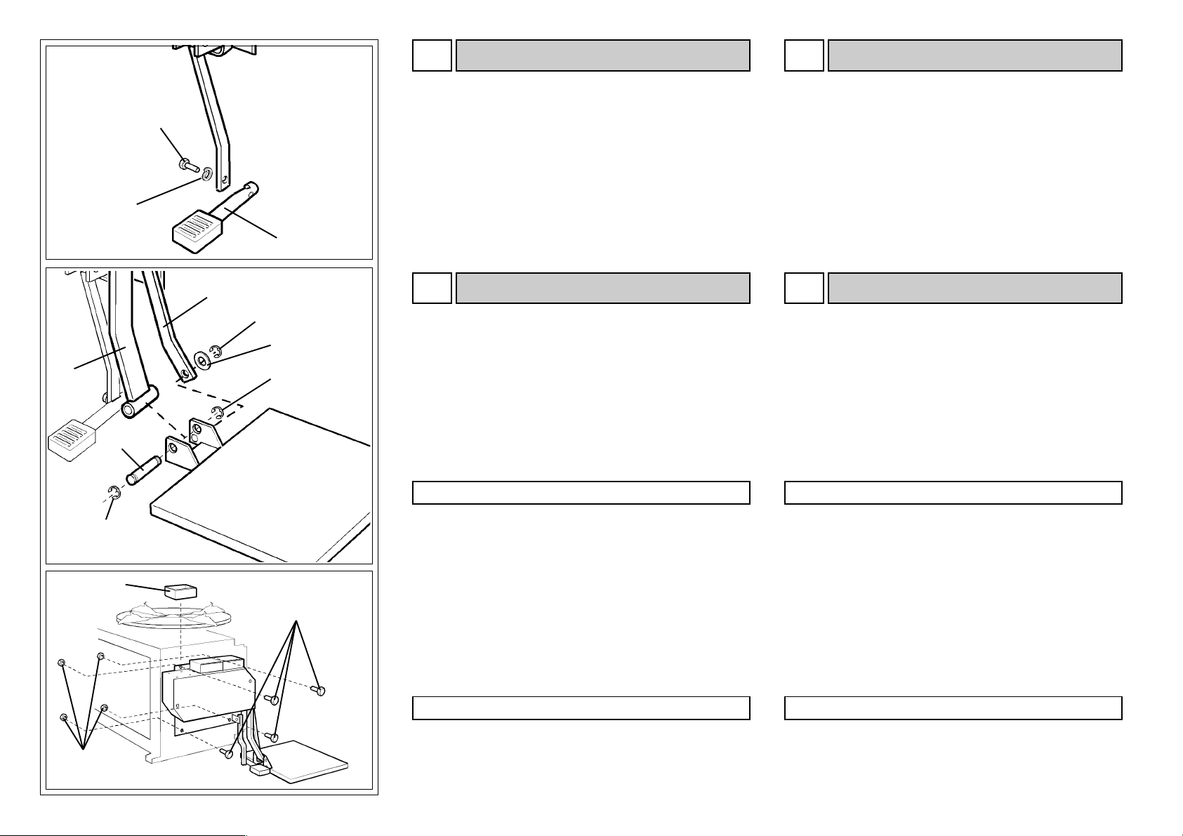
1) Fixer la pé ale e comman e ( , Fig. C) à la tige e comman e
e la vanne u SR 60, en utilisant la vis M 8x25 (4, Fig. C) et la
ron elle Grower iam. 8 (5, Fig. C) comme in iqué sur la figure.
2) Fixer la barre anti-rotation (6, Fig. D) sur l’axe soli aire e la
plate-forme en interposant entre celle-ci et l’anneau Benzing (20,
Fig. D) la ron elle (7, Fig. D), comme in iqué ans la figure.
) Relier la plate-forme au bras e levage (8, Fig. D) et les anneaux
Benzing (10, Fig. D).
1) D s Betätigungsped l (3, Abb. C) n der Ventilsch ltst nge der
SR 60 befestigen. D zu die Schr ube M 8x25 (4, Abb. C) und die
Federscheibe ( 8 (5, Abb. C) benutzen, so wie es der Abbildung zu
entnehmen ist.
2) An dem Bolzen, der zur Pl ttform gehört, die Rot tions-
verhinderungsst nge (6, Abb. D) befestigen und zwischen diese und
den Benzing-Ring (20, Abb. D) die Unterlegscheibe ( , Abb. D)
stecken, so wie es in der Abbildung gezeigt ist.
3) Die Pl ttform m Hebe rm (8, Abb. D) nschließen. D zu den
Drehbolzen (9, Abb. D) und die Benzing-Ringe (10, Abb. D) benutzen.
1) Fijar el pe al e accionamiento ( , Fig. C) a la varilla e
man o válvula e la SR 60, utilizan o el tornillo M 8x25 (4, Fig.
C) y la aran ela Grower iám. 8 (5, Fig. C) como se in ica en
la figura.
2) Fijar la varilla antirrotación en el perno soli ario e la
plataforma (6, Fig. D) interponien o entre ésta y el anillo Benzing
(20, Fig. D) la aran ela (7, Fig. D), como se in ica en la figura.
) Acoplar la plataforma al brazo e elevación (8, Fig. D)
utilizan o el pivote (9, Fig.D ) y los anillos (10, Fig. D).
MONTAGE DER SR 60
MONTAGE DU SR 60
5.1 5.1
MONTAJE DE SR 60
5.1
BEFESTIGUNG DER SR 60
5.2
1) Die linke Seitenw nd des Reifenmontiergerätes bnehmen.
2) Den Ped lschutz usb uen. Wenn die Hebevorrichtung SR 60
vorh nden ist, wird dieser nicht gebr ucht, weil die SR 60 schon
eine Schutzfunktion usübt.
3) F lls uf der Vorderseite der Reifenmontierm schine nicht lle
Löcher zur Befestigung der Vorrichtung vorh nden sind, müssen
diese noch gebohrt werden. D zu die Bohrsch blone (K rton)
benutzen, die zum Lieferumf ng gehört.
- D nn folgenderm ßen vorgehen:
S 409
a) Die Bohrsch blone uf die Reifenmontierm schine legen,
wobei die Löcher, die durch die roten Pfeile uf der Sch blone
ngezeigt werden, mit denen unten uf der Vorderseite der
Reifenmontierm schine zus mmenf llen müssen (diese Löcher
sind vorher zur Befestigung der Ped lschutzes verwendet worden).
b) Mit einer H ndbohrm schine die Löcher bohren, die uf der
Bohrsch blone ngezeigt sind. Jeweils einen Bohrer mit dem
Durchmesser benutzen, der uf der Sch blone für d s Loch
ngegeben ist.
c) Die Bohrsch blone entfernen.
S 412 - S 415 - S 419 - S 425 - S 432
FIXATION DU SR 60
5.2
a) Positionner le gabarit e perçage en superposant les trous
in iqués par les flèches rouges sur le gabarit aux trous en bas u
panneau frontal u émonte-pneus (les trous sont ceux
normalement utilisés pour la fixation u protecteur es pé ales).
b) A l’ai e ’une perceuse portative percer les trous in iqués sur
le gabarit e perçage, en utilisant un foret u iamètre spécifié
sur le gabarit.
c) Enlever le gabarit e perçage.
S 409
a) A l’ai e ’une perceuse portatives muni ’un forêt e 6,5
mm e iamètre, élargir les trous en haut sur le panneau frontal
u émonte-pneus, normalement utilisés pour la protection es
pé ales.
1) Déposer le flanc gauche u émonte-pneus.
2) Démonter la protection es pé ales: celle-ci n’est pas utilisée
en présence u SR 60 qui fait fonction e protecteur.
) S’il n’y a pas tous les trous e fixation u ispositif sur la partie
frontale u émonte-pneus, il fau ra les percer en utilisant le
gabarit e perçage en carton, livré ans le kit e montage.
- Procé er e la manière suivante:
a) Die Löcher oben uf der Vorderseite der Reifenmontierm schine,
die in der Regel für die Befestigung des Ped lschutzes verwendet
werden, mit einer H ndbohrm schine mit einem Bohrer von 6,5 mm
ufbohren.
S 409
FIJACION DE LA SR 60
5.2
S 412 - S 415 - S 419 - S 425 - S 4 2
1) Quitar flanco izquier o e la esmonta ora.
2) Desmontar la protección e los pe ales: no se utiliza en
presencia e la SR 60 ya que funciona como protección.
) Si en la parte frontal e la esmonta ora no estuvieran
hechos los agujeros e fijación el ispositivo, éstos se ten rían
que hacer usan o la plantilla e tala ro que se a en
otación.
- Para ello seguir las siguientes in icaciones:
a) Colocar la plantilla e tala ro sobreponien o los agujeros
in ica os por las flechas rojas e la plantilla, a los e la parte
frontal e la esmonta ora (los agujeros son los que se usan
normalmente para la fijación e la protección e los pe ales).
b) Con un tala ro e mano realizar los agujeros in ica os en
la plantilla, usan o puntas e tala ro con el iámetro in ica o
en la plantilla.
c) Quitar la plantilla e tala ro.
a) Usan o un tala ro e mano con una punta e 6,5 mm e
iámetro, ensanchar los agujeros en la parte superior el frontal
e la esmonta ora, normalmente se utilizan para la fijación
e la protección e los pe ales.
S 412 - S 415 - S 419 - S 425 - S 4 2

10 -
SR 60
F
17
16
14
15
18
G
b) Posizionare la maschera i foratura sovrapponen o i fori
in icati alle frecce gialle sulla maschera, a quelli appena al-
largati.
c) Con l'ausilio i un trapano a mano praticare i fori in icati
sulla maschera i foratura, utilizzan o punte i foratura el ia-
metro specificato sulla maschera stessa.
d) Rimuovere la maschera i foratura.
4) Dopo aver tolto la maschera i foratura, fissare il ispositivo
SR 60 allo smontagomme utilizzan o:
n.4 viti M 6x16 (11, Fig. E)
n.4 a i M 6 (12, Fig. E)
5) Montare le vaschette portaoggetti (1 , Fig. E) a incastro
negli appositi fori posti sul ispositivo.
E
11
12
13
b) Position the templ te pl cing the holes indic ted by the
yellow rrows on top of those you h ve just widened.
c) Use h nd drill to m ke the holes shown on the templ te.
Use the drill di meter given on the templ te.
d) Remove the drilling templ te.
4) After you h ve removed the templ te, tt ch the SR 60 to
the tyre ch nging using:
n. 4 M 6x16 screws (11, Fig. E)
n. 4 M6 nuts (12, Fig. E)
5) Inst ll the sn p in stor ge tr ys (13, Fig. E) using the holes
pre-drilled on the SR 60.
N.B.: Prima di questa operazione scollegare lo smontagomme
da ogni sua fonte di alimentazione elettrica e pneumatica.
1) Inserire a fon o un capo el tubo ø 6-4 (14, Fig. F), fornito
nel kit, nel raccor o a innesto rapi o (17, Fig. F) ell' SR 60
orientato verso l'interno ello smontagomme.
2) In posizione conveniente all'interno ella carcassa, tagliare
in mo o netto con un cutter il tubo i alimentazione ell'aria
compressa (15, Fig. F), proveniente al gruppo filtro-regolatore
e iretto alla pe aliera ello smontagomme.
) Installare il raccor o (16, Fig. F) in otazione, in mo o a
ripristinare l'ingresso i alimentazione appena interrotto, e
avere a isposizione un ulteriore attacco ell'aria.
4) Collegare il tubo proveniente all' SR 60 (14, Fig. F) al rac-
cor o appena installato.
5) Rimontare la fiancata sinistra e ripristinare i collegamenti i
alimentazione allo smontagomme.
5. 5.3
COMPRESSED AIR HOOK UP
ALLACCIAMENTO PNEUMATICO
NB: Before any installation work, check to make sure that the
tyre changer is disconnected from all electric and pneumatic
supply sources.
1) Insert one end of the di m. 6-4 hose (14, fig. F) in the inst ll -
tion kit, onto the quick coupling fitting (1 , Fig. F) on the SR 60
turned tow rds the inside of the ch nger.
2) At convenient point inside the c binet, use cutter to
m ke nice cle n cut through the compressed ir feed hose
(15, Fig. F) from the filter/pressure regul tor nd going tow rds
the tyre ch nger ped l unit.
3) Inst ll the fitting (16, Fig. F) in the kit to re-est blish the com-
pressed ir supply you just cut off. h ve nother ir connect to
h nd.
4) Connect the hose from the SR 60 (14, Fig. F) to the fitting you
just inst lled.
5) Repl ce the left side p nel nd turn the tyre ch nger power
supplies b ck on.

SR 60
- 11
b) Poser le gabarit e perçage en superposant les trous in iqués
par les flèches jaunes sur le gabarit sur ceux qui viennent ’être
élargis.
c) Avec une perceuse portative percer les trous in iqués sur le
gabarit e perçage, en utilisant un forêt u iamètre spécifié
sur le gabarit.
d) Enlever le gabarit e perçage.
4) Après avoir enlevé le gabarit e perçage, fixer le ispositif
SR 60 au émonte-pneus en utilisant:
n.4 vis M 6x16 (11, Fig. E)
n.4 écrous M 6 (12, Fig. E)
5) Monter les casiers porte-objets (1 , Fig. E) en les encastrant
ans leursorifices sur le ispositif.
b) Die Bohrsch blone so uflegen, d ß die Löcher, die uf der
Sch blone durch die gelben Pfeile ngezeigt werden, über die
soeben ufgebohrten Locher f llen.
c) Mit einer H ndbohrm schine die Löcher bohren, die uf der
Bohrsch blone ngezeigt sind. Jeweils einen Bohrer mit dem
Durchmesser benutzen, der uf der Sch blone für d s Loch
ngegeben ist.
d) Die Bohrsch blone entfernen.
4) N ch dem Abnehmen der Bohrsch blone die
Hebevorrichtung SR 60 n der Reifenmontierm schine
befestigen. D zu benutzt m n:
n. 4 Schr uben M 6x6 (11, Abb. E)
n. 4 Muttern M 6 (12, Abb. E).
5) Die Abl gesch len (13, Abb. E) in die Löcher uf der
Vorrichtung einr sten l ssen.
b) Colocar la plantilla e tala ro sobreponien o los agujeros
in ica os por las fechas amarillas en la plantilla, a los que se
acaban e ensanchar.
c) Con el tala ro e mano realizar los agujeros in ica os en
la plantilla, utilizan o puntas con el iámetro especifica o en
la plantilla.
d) Quitar la plantilla.
4) Una vez quita a la plantilla, fijar el ispositivo SR 60 a la
esmonta ora utilizan o:
n. 4 tornillos M 6x16 (11, Fig. E)
n. 4 tuercas M 6 (12, Fig. E)
5) Encajar la caja porta-objetos (1 , Fig. E) en sus agujeros en
el ispositivo.
PNEUMATISCHER ANSCHLUSS CONEXION NEUMATICA
5.3 5.5.
RACCORDEMENT PNEUMATIQUE
Anm.: Bevor man diese Arbeiten durchführt, sicherstellen, daß die
Reifenmontiermaschine von allen elektrischen und pneumatischen
Energieversorgungsquellen getrennt ist.
1) Ein Ende des Schl uches ø 6-4 (14, Abb. F), d s zum Lieferumf ng
gehört, fest uf den Stutzen der Steckkupplung (1 , Abb. F) der SR
60 stecken, der uf d s Innere der Reifenmontierm schine zeigt.
2) Innerh lb des Untergestells der M schine den Schl uch zur
Druckluftversorgung (15, Abb. F), der von der W rtungseinheit mit
Filter und Regler kommt und zu den Ped len der
Reifenmontierm schine geht, mit einem Cutter durchschneiden.
3) D s zum Lieferumf ng gehörende T-Stück (16, Abb. F) so
inst llieren, d ß die soeben durchgeschnittene Schl uchleitung
wieder hergestellt wird, so d ß m n ber einen weiteren Anschluß
zur Verfügung h t.
4) Den von der SR 60 kommenden Schl uch (14, Abb. F) n d s
soeben inst llierte T-Stück nschließen.
5) Die linken Seitenw nd der Reifenmontierm schine wieder
ufsetzen und die Energieversorgung wieder nschließen.
N.B.: Antes de realizar esta operación desconectar la
desmontadora de toda fuente de alimentación eléctrica y
neumática.
1) Acoplar a fon o una extremi a el tubo iám. 6-4 (14, Fig.
F) suministra o en el kit, en la unión e acoplamiento rápi o
(17, Fig. F) e la SR 60 orienta o hacia el interior e la
esmonta ora.
2) En la posición conveniente en el interior e la estructura,
cortar con un cutter el tubo e alimentación el aire
comprimi o (15, Fig.F), que proviene el grupo filtro-regula or
y va hacia el grupo pe al e la esmonta ora.
) Instalar la unión (16, Fig.F) para restablecer la entra a e
alimentación que se había interrumpi o y tener a isposición
otra unión el aire.
4) Conectar el tubo que proviene e la SR 60 (14, Fig.F) a la
unión que se acaba e instalar.
5) Volver a montar el flanco izquier o y restablecer las
conexiones e alimentación e la esmonta ora.
N.B.: Avant d’effectuer cette opération débrancher le démonte-
pneus de toute source d’alimentation électrique et
pneumatique.
1) Brancher à fon une extrémité u tube iam. 6-4 (14, Fig. F)
livré ans le kit, sur le raccor à branchement rapi e (17, Fig.
F) u SR 60 orienté vers l’intérieur u émonte-pneus.
2) Dans une position pratique à l’intérieur e la carcasse et à
l’ai e ’un cutter couper net le tube ’alimentation e l’air
comprimé (15, Fig. F) qui provient u groupe filtre-régulateur
et qui est irigé vers le pé alier u émonte-pneus.
) Monter le raccor (16, Fig. F) livré en équipement, pour
rétablir l’arrivée e l’alimentation qui vient ’être coupée et
isposer ainsi ’un raccor supplémentaire e l’air.
4) Brancher le tube qui provient u SR 60 (14, Fig. F) au raccor
qui vient ’être monté.
5) Remonter le flanc gauche et rétablir les branchements
’alimentation u émonte-pneus.

12 -
SR 60
18
G
CONTROLS
6
IDENTIFICAZIONE DEI COMANDI
6
Il sollevatore SR 60 ispone i un unico pe ale i coman o utile
a operare sia il sollevamento che l'abbassamento ella pe a-
na portaruota.
- Premen o a fon o e mantenen o premuto il pe ale
(18, Fig.
G) si ottiene il sollevamento ella pe ana e il suo staziona-
mento alla massima altezza.
- Rilascian o il pe ale (18, Fig. G) si ottiene prontamente l'ab-
bassamento completo ella pe ana fino a terra.
The SR 60 h s been designed to f cilit te movement of tyres
from the floor to the turnt ble nd vice-vers .
Positioning the wheel:
1) Pl ce the wheel vertic lly on the pl tform.
2) Press the ped l (18, Fig. G) to r ise the pl tform. Hold the
wheel with one h nd s the pl tform moves so th t the wheel
is lw ys b l nced.
3) Pl ce the wheel on the turnt ble.
4) Rele se the ped l (18, Fig. G) to lower the pl tform.
Removing the wheel:
1) Uncl mp the wheel from the turnt ble grippers.
2) Press the ped l (18, fig. G) to r ise the pl tform nd hold the
pl tform down.
3) Pl ce the wheel vertic lly on the pl tform.
4) Rele se the ped l (18, Fig. G) to lower the wheel to the floor.
Hold the wheel with one h nd s the pl tform moves so th t
the wheel is lw ys b l nced.
N.B.: The tyre lifting pl tform is v il ble in two versions: SR 60
without rolls (Fig. G) nd SR 60/R with rolls (Fig. G/1).
Rolls f cilit te wheel rot tion during be d bre king oper tion,
speeding up this oper tion.
ATTENZIONE!
Il pedale comando deve essere azionato,
e può essere mantenuto premuto, esclusivamen-
te con il piede da parte di chi opera.
DANGER!
The control pedal must only be operated and
held down with the foot of the person operating
the machine.
USO
7OPERATION
7
The SR 60 tyre lift h s single control ped l used to oper te the
lift nd to lower the tyre pl tform.
- When the ped l is pressed nd held down (18, Fig. G) the
pl tform is r ised until it re ches its high position.
- When the ped l is rele se (18, Fig. G), the pl tform immedi-
tely lowers ll the w y to the floor.
Il ispositivo SR 60 é stato concepito per facilitare la movimen-
tazione elle ruote a terra all'autocentrante e viceversa.
Posizionamento ruota:
1) Sistemare la ruota in verticale sulla pe ana.
2) Premere il pe ale (18, Fig. G) per ottenere l'innalzamento
ella pe ana, accompagnan o e mantenen o la ruota in
equilibrio con una mano per tutta la corsa.
3) Posizionare la ruota sull'autocentrante.
4) Rilasciare il pe ale (18, Fig. G) per riabbassare la pe ana.
Rimozione ruota:
1) Sbloccare la ruota alle griffe ell'autocentrante.
2) Premere il pe ale (18, Fig. G) per ottenere l'innalzamento
ella pe ana e mantenerlo premuto.
3) Posizionare la ruota in verticale sulla pe ana.
4) Rilasciare il pe ale (18, Fig. G) per riportare la ruota a terra,
accompagnan o e mantenen o la ruota in equilibrio con una
mano per tutta la corsa.
N.B.: La pe ana i sollevamento ruota é isponibile nella ver-
sione SR 60 senza rulli (Fig.G) e nella versione SR 60/R con rulli
(Fig.G/1).
I rulli agevolano la rotazione manuale ella ruota urante la
stallonatura, velocizzan o l'operazione.
G/1

SR 60
- 13
6
IDENTIFICATION DES COMMANDES
6
IDENTIFICACION DE LOS MANDOS
6
KENNZEICHNUNG DER
BEDIENUNGSVORRICHTUNGEN
Le ispositif SR 60 a été conçu pour faciliter la manutention
es roues epuis le sol sur le plateau autocentrant et
inversement.
Positionnement de la roue:
1) Placer la roue à l’horizontale sur la plate-forme.
2) Appuyer sur la pé ale (18, Fig. G) pour soulever la plate-
forme en accompagnant et en tenant la roue en équilibre
avec une mains pen ant toute la course.
3) Placer la roue sur le plateau autocentrant.
4) Relâcher la pé ale (18, Fig. G) pour abaisser la plate-forme.
Dépose de la roue:
1) Débloquer la roue es griffes e l’autocentrant.
2) Appuyer sur la pé ale (18, Fig. G) pour soulever la plate-
forme et la maintenir enfoncée.
3) Placer la roue à la verticale sur la plate-forme.
4) Relâcher la pé ale (18, Fig. G) pour ramener la roue au sol,
en accompagnant et en tenant la roue en équilibre avec une
main pen ant toute la course.
N.B.: L'elevateur roue est isponible soit ans la version SR 60
sans rouleaux (Fig. G), soit ans la version SR 60/R avec rouleaux
(Fig. G/1).
Les rouleaux facilitent la rotation manuel e la roue pen ant
l'étalonage, ren ant l'opération plus vite.
ATTENTION!
La pédale de commande doit être
actionnée, et peut être maintenue enfoncée,
exclusivement par le pied de l’opérateur.
UTILISATION7
ACHTUNG !
Das Pedal darf und kann nur vom Bediener
betätigt und durchgetreten werden.
¡ATENCION!
El pedal de mando debe ser accionado y
puede permanecer pisado exclusivamente por
el pie del operario.
BEDIENUNG USO77
Der Heber SR 60 h t nur ein einziges Ped l, d s zum Heben
und Senken der Pl ttform benutzt wird, uf der der Reifen steht.
- D s Ped l (18, Abb. G) drücken und g nz durchgetreten
h lten, um die Pl ttform zu heben und uf die m xim le Höhe
zu bringen.
- Wenn m n d s Ped l (18, Abb. G) losläßt, wird die Pl ttform
wieder bis zum Boden durchgesenkt.
L’élévateur SR 60 ispose ’une seule pé ale e comman e
servant à la montée et à la escente e la plate-forme e
soulèvement e la rouie.
- En appuyant à fon et en maintenant la pé ale enfoncée
(18, Fig. G) on obtient la montée e la plate-forme et son
stationnement à la hauteur maximale.
- En relâchant la pé ale (18, Fig. G) on obtient la escente
rapi e et totale e la plate-forme jusqu’au sol.
El eleva or SR 60 tiene sólo un pe al e man o tanto para
elevar como para bajar la plataforma portarrue a.
- Pisan o a fon o el pe al y mantenién olo así (18, Fig.G) se
eleva la plataforma y se para a su altura máxima.
- Soltan o el pe al (18, Fig.G) se baja la plataforma comple-
tamente hasta el suelo.
Die Hebevorrichtung SR 60 ist entwickelt worden, um d s R d
einf cher vom Boden und uf die Pl ttform und umgekehrt
bringen zu können.
Rad aufstellen:
1) D s R d senkrecht uf die Pl ttform stellen.
2) D s Ped l (18, Abb. G) drücken, um die Pl ttform zu heben.
D s R d d bei mit der H nd begleiten, d mit es im
Gleichgewicht stehen bleibt.
3) D s R d uf die Sp nnfl nsch bringen.
4) D s Ped l (18, Abb. G) losl ssen, um die Pl ttform zu senken.
Rad entfernen:
1) D s R d von den Sp nnkl uen der M schine befreien.
2) D s Ped l (18, Abb. G) betätigen, d mit die Pl ttform
hochfährt. D s Ped l gedrückt h lten, um sie oben zu beh lten.
3) D s R d senkrecht uf die Pl ttform stellen.
4) D s Ped l (18, Abb. G) losl ssen, um d s R d zum Boden
zurückzubringen. Es d bei mit der H nd festh lten, d mit es
nicht umfällt.
Anm.: Der R dherber ist in zwei Versionen zur Verfügung: SR 60
ohne Rollen (Abb. G) und SR 60/R mit Rollen (Abb. G/1).
Die Rollen erleichtern die m nuelle Drehung des R des
während der Abdrückung und m chen diese Oper tion
schneller.
El ispositivo ha si o fabrica o para facilitar los
esplazamientos e las rue as es e el suelo hasta el plato
autocentrante y viceversa.
Posicionamiento de la rueda:
1) Colocar verticalmente la rue a en la plataforma.
2) Pisar el pe al (18, Fig.G) para elevar la plataforma, sujetan o
con una mano la rue a y mantenién ola en equilibrio uran-
te to o el recorri o.
3) Colocar la rue a en el plato autocentrante.
4) Soltar el pe al (18, Fig.G) para bajar la plataforma.
Quitar la rueda:
1) Desbloquear la rue a e las garras el plato autocentrante.
2) Pisar el pe al (18, Fig.G) para elevar la plataforma y mante-
nerlo pisa o.
3) Colocar verticalmente la rue a en la plataforma.
4) Soltar el pe al (18, Fig.G) para poner la rue a en el suelo,
sujetan o con una mano la rue a y mantenién ola en equili-
brio urante to o el recorri o.
N.B.: El ispositivo eleva or e rue as, se encuentra en os
versiones SR 60 sin rolos (Fig.G) o SR 60/R con rolos (Fig.G/1).
Los rolos ayu án al girar manualmente la rue a, que sea más
veloz la operación e estalona ura.

14 -
SR 60
H
18
G
DIMENSIONI D'INGOMBRO
8
OVERALL DIMENSIONS
8
In figura H sono riportate le imensioni 'ingombro el isposi-
tivo i sollevamento SR 60.
9
INCONVENIENTI/CAUSE/RIMEDI
9
TROUBLE SHOOTING
ATTENZIONE:
Se le indicazioni di seguito elencate non
riportano il dispositivo ad un corretto
funzionamento, o si riscontrano anomalie di altro
tipo, sospendere l'uso del sollevatore e chiamare al
più presto il servizio tecnico di assistenza.
WARNING:
1) L'alimentazione pneumatica non arriva allo
smontagomme o risulta insufficente.
2) Non arriva pressione al cilin ro el sollevatore.
1)
Inserire correttamente il tubo ell'aria i alimenta-
zione e verificare che fornisca la pressione necessaria.
2) Verificare che i tubi ell'SR 60 non siano ostruiti a
piegature acci entali.
PROBLEMACAUSERIMEDI
Azionando il pedale (18, Fig. G) la pedana di solle-
vamento non si muove
PROBLEMCAUSEREMEDY
Figure H highlights the over ll dimensions of the SR 60 wheel lift.
If the information given in the table be-
low do not solve the problem or if you find
other kinds of problems, stop using the wheel lift and
call your nearest SICE Technical Assistance Centre.
1) Insert the compressed ir supply hose correctly
nd check if the pressure is sufficient.
2) Check if the SR 60 ir hoses re clogged or cci-
dent lly crimped.
When the pedal (18, Fig. G) is pressed, the lift plat-
form does not move.
1) The compressed ir supply does not re ch the
tyre ch nger or is insufficient.
2) Compressed ir does not re ch the lift cylinder.

SR 60
- 15
PLATZBEDARF DIMENSIONES MAXIMAS
DIMENSIONS D'ENCOMBREMENT
888
9
FEHLERSUCHE
9
INCONVENIENTES/CAUSAS/REMEDIOS
9
INCONVENIENTS/CAUSES/REMEDES
ACHTUNG:
Falls die weiter unten angegebenen
Hinweise Ihnen nicht dabei helfen, den
korrekten Betrieb der Hebevorrichtung SR 60 wieder
herzustellen, wenden Sie sich an den technischen
Kundendienst.
ATENCION:
Si con las siguientes indicaciones el di-
spositivo no funcionase correctamente o
se observaran anomalías de otro tipo, no usar el
elevador y llamar lo antes posible al servicio técnico
de asistencia.
ATTENTION!
Si les indications énumérées ci-dessous ne
permettent pas de remettre le dispositif en
parfait état, ou si d’autres anomalies se manifestent,
arrêter l’utilisation de l’élévateur est contacter
promptement le service après-vente.
Wenn man das Pedal (18, Abb. G) betätigt, bewegt
sich die Hebeplattform nicht.
PROBLEMURSACHEABHILFE
1) No llega la alimentación neumática a la
esmonta ora o es insuficiente.
2) No llega presión al cilin ro el eleva or.
PROBLEMACAUSAREMEDIOS
Al pisar el pedal (18, Fig.G) la plataforma de
elevación no se mueve.
1) L’alimentation pneumatique n’arrive pas au
émonte-pneus ou est insuffisante.
2) Il n’arrive pas e pression au vérin e l’élévateur.
ANOMALIECAUSESREMEDES
Les imensions ’encombrement u ispositif élévateur SR 60
sont in iquées ans la figure H.
La plate-forme de levage ne bouge pas quand on
actionne la pédale (18, Fig. G).
In der Abbildung H sind die Abmessungen der Hebevorrichtung
SR 60 zu sehen.
1) Die pneum tische Energieversorgung kommt nicht
bei der Hebevorrichtung n oder der Druck ist zu
niedrig.
2) Der Hebezylinder erhält keinen Druck.
1) Den Schl uch der Druckluftversorgung korrekt
nschließen und prüfen, ob der erforderliche Druckwert
geliefert wird.
2) Sicherstellen, d ß die Schläuche der SR 60 nicht gebogen
sind oder der Durchfluß sonstwie verhindert wird.
1) Raccor er correctement le tube e l’air
’alimentation et vérifier qu’il fournit la pression requise.
2) Vérifier que les tubes u SR 60 ne sont pas obstrués
par es plis acci entels.
En la figura H aparecen las imensiones máximas el ispositi-
vo e elevación SR 60.
1) Acoplar bien el tubo el aire e alimentación y
verificar que proporcione la presión necesaria.
2) Verificar que los tubos e la SR 60 no estén obla os.

SOCIETA’ ITALIANA COSTRUZIONI ELETTROMECCANICHE S.I.C.E.-S.p.A.
Via Modena, 4 - 42015 CORREGGIO (R.E.) - ITALY
Tel. (0522) 693640 (8 linee r.a.) Tel. (059) 348611 Export ept.
Fax (0522) 642882 Factory Fax (059) 359358 Export ept.
La SICE si riserva di appor-
tare modifiche alle proprie
macchine in qualsiasi mo-
mento e senza preavviso
PUBBLICAZIONI SICE
E izione 01/98
STAMPATO IN ITALIA
Co ice N°.:3900005
Non si risponde per danni e/
o lesioni derivanti da un uti-
lizzo diverso da quello qui
specificato o dalla inosser-
vanza delle istruzioni conte-
nute nel presente manuale.
SICE reserves the right to modify
its machine at any time without
prior notice.
SICE declines any and all liabil-
ity for injury to persons or dam-
age to things caused by use of
the machine other than that
specified or failure to observe
the instructions detailed in this
Manual.
Sice se réserve le droit
d’apporter les modifications à
ses machines à tout moment et
sans préavis.
Sice décline toute
responsabilité en cas de
dommages dus à une
mauvaise utilisation ou à
l’inobservation des instructions
de cette notice.
Firma SICE behält sich das
Recht vor, jederzeit ohne
Vorbescheid Änderungen an
ihren Maschinen vorzunehmen.
Der Hersteller haftet nicht für
Schäden und/oder
Verletzungen infolge der
Benutzung, die nicht der hier
beschriebenen entspricht, oder
infolge der Nichtbeachtung der
Anweisungen, die in diesem
Handbuch stehen.
La SICE se reserva el derecho
de realizar modificaciones en
sus máquinas en cualquier mo-
mento sin previo aviso.
No se hace responsable de los
daños y/o lesiones provocados
por un uso diferente al que se
especifica aquí o por no
respetar las instrucciones de
este manual.
SICE PUBLISHING
Edition 01/98
PRINTED IN ITALY
Ordering Code N
°
3900005
PUBLICATIONS SICE
E ition 01/98
IMPRIMÉ EN ITALIE
Co e N°.:3900005
SICE-VERÖFFENTLICHUNGEN
Ausg be 01/98
IN ITALIEN GEDRUCKT
M t. Nr.: 3900005
PUBLICACIONES SICE
E icion 01/98
ESTAMPADO EN ITALIA
CODIGO N°.:3900005
GBIFDE
This manual suits for next models
1
Other SICE Lifting System manuals
Popular Lifting System manuals by other brands

EINHELL
EINHELL TC-EH 1000 Original operating instructions

Cama
Cama Handi-Lift ML7 installation manual

twin busch
twin busch TW236M Installation, operation and maintenance manual

Jet
Jet SLT-660F Operating instructions and parts manual

Atlas
Atlas BP12000 Installation & operation manual

WALTCO
WALTCO HDC-33 installation manual