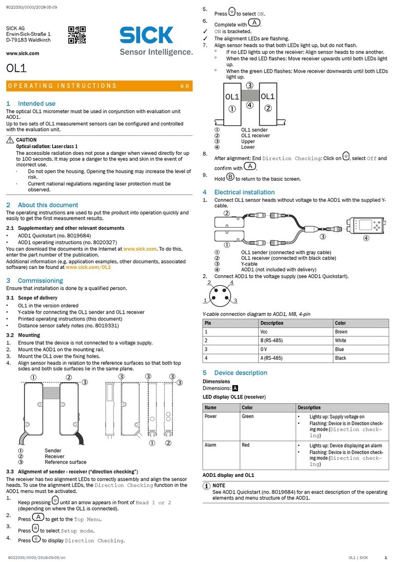
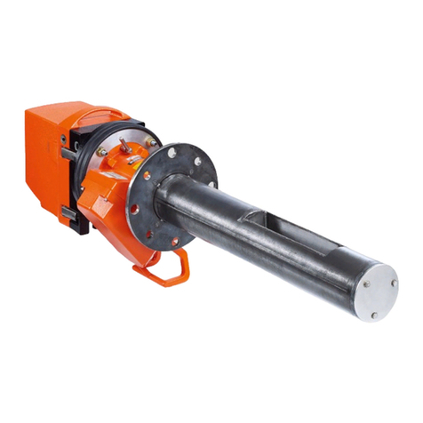
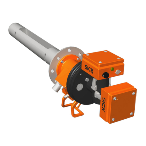
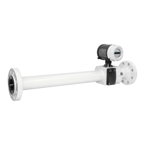
SICK FLOWSIC600 Manual

TECHNICAL INFORMATION
Title
Ultrasonic Gas Flow Meter
for Custody Transfer
and Process Applications
MEPAFLOW600 CBM and Firmware V3.6.xx
FLOWSIC600
Ultrasonic Gas Flow Meter

2 FLOWSIC600 · Technical Information · 8010125 V 4.0 · © SICK AG
Document Information
Product
Product name: FLOWSIC600
Document ID
Title: Technical Information FLOWSIC600
Part No.: 8010125
Version: 4.0
Release: 2014-09
Publisher
SICK AG
Erwin-Sick-Str. 1 · D-79183 Waldkirch · Germany
Tel.: +49 7641 469-0
Fax: +49 7641 469-11 49
E-mail: info.pa@sick.de
Place of Manufacture
SICK Engineering GmbH
Bergener Ring 27 · D-01458 Ottendorf-Okrilla · Germany
Trademarks
IBM is a trademark of the International Business Machine
Corporation.
MS-DOS is a trademark of the Microsoft Corporation.
Windows is a trademark of the Microsoft Corporation.
Other product names used in this document may also be
trademarks and are only used for identification purposes.
Guarantee Information
Specified product characteristics and technical data do not serve
as guarantee declarations.
© SICK AG. All rights reserved.
Glossary
Abbreviations used in this manual
act. actual (under operating/flowing conditions)
AGC Automatic Gain Control
ANSI American National Standards Institute
ASCII American Standard Code for Information
Interchange
ASME American Society of Mechanical Engineers
ATEX Atmosphères Explosifs: Abbreviation for Euro-
pean standards that govern safety in poten-
tially explosive atmospheres
AWG American Wire Gage
CBM Condition Based Maintenance
CSA Canadian Standards Association
DC Direct Current
DIN Deutsches Institut für Normung
DN Nominal Diameter (internal)
DSP Digital Signal Processor
EC European Community
EMC Electro Magnetisc Ccompatibility
EN Euro Norm (European Standard)
EVC Electronic Volume Corrector
Ex Potentially explosive atmosphere
HARTCommunication interface
IEC International Electrotechnical Commission
IECEx EC system for certification in accordance with
standards for devices for use in potentially
explosive atmospheres
LCD Liquid Crystal Display
LED Light Emitting Diode
MDR Manufacturer Data Record
MEPAFLOW Menu-assisted Parameterization and Diagno-
sis for FLOWSIC600
NAMUR Normenarbeitsgemeinschaft für Mess- und
Regeltechnik in der chemischen Industrie
(now "Interessengemeinschaft Prozessleit-
technik der chemischen und pharmazeut-
ischen Industrie"; ~ Association for
Instrumentation and Control Standards in the
Chemical Industry)
norm. normalized/corrected (under standard condi-
tions)
OI Operating Instructions
OIML Organisation Internationale de Metrologie
Legale
PC Personal Computer
PTB Physikalisch Technische Bundesanstalt
(~ Federal Metrology Office in Germany)
Reg. # Register number
RTU Remote Terminal Unit
SNR Signal Noise Ratio
SPU Signal Processing Unit
TI Technical Information
VDE Verband der Elektrotechnik Elektronik Infor-
mationstechnik
(~ Association of German Electrical Engineers)

FLOWSIC600 · Technical Information · 8010125 V4.0 · © SICK AG 3
Warning Symbols
Warning Levels / Signal Words
WARNING
Risk or hazardous situation which could result in severe personal
injury or death.
CAUTION
Hazard or unsafe practice which could result in personal injury or
property damage.
NOTICE
Hazard which could result in property damage.
Information Symbols
Hazard (general)
Hazard in potentially explosive atmospheres
Hazard by voltage
Information about the use in potentially explosive
atmospheres
Important technical information for this product
Important information on electric or electronic
functions
Supplementary information
Link to information at another place

Contents
4 FLOWSIC600 · Technical Information · 8010125 V 4.0 · © SICK AG
1Important Information . . . . . . . . . . . . . . . . . . . . . . . . . . . . . . . . . . . . . . . . . . . . . . . 9
1.1 About this document . . . . . . . . . . . . . . . . . . . . . . . . . . . . . . . . . . . . . . . . . . . . . . . . . . . . . . . . 10
1.2 Scope of document. . . . . . . . . . . . . . . . . . . . . . . . . . . . . . . . . . . . . . . . . . . . . . . . . . . . . . . . . . 10
1.3 Safety instructions . . . . . . . . . . . . . . . . . . . . . . . . . . . . . . . . . . . . . . . . . . . . . . . . . . . . . . . . . . 11
1.3.1 Intended use of the equipment . . . . . . . . . . . . . . . . . . . . . . . . . . . . . . . . . . . . . . . . . . . . 11
1.4 Authorized staff . . . . . . . . . . . . . . . . . . . . . . . . . . . . . . . . . . . . . . . . . . . . . . . . . . . . . . . . . . . . . 11
1.5 General safety instructions and protective measures . . . . . . . . . . . . . . . . . . . . . . . . . . . 12
1.6 Dangers due to hot, corrosive and explosive gases and high pressure . . . . . . . . . . . . 12
1.7 Dangers due to heavy loads . . . . . . . . . . . . . . . . . . . . . . . . . . . . . . . . . . . . . . . . . . . . . . . . . . 13
1.8 Environmental information and instructions for disposal . . . . . . . . . . . . . . . . . . . . . . . . 13
2Product Description. . . . . . . . . . . . . . . . . . . . . . . . . . . . . . . . . . . . . . . . . . . . . . . . . . 15
2.1 Features and applications . . . . . . . . . . . . . . . . . . . . . . . . . . . . . . . . . . . . . . . . . . . . . . . . . . . 16
2.1.1 FLOWSIC600 1-path, FLOWSIC600 2-path, FLOWSIC600 4-path . . . . . . . . . . . . . . 17
2.1.2 FLOWSIC600 2plex (4 + 1 CBM Design). . . . . . . . . . . . . . . . . . . . . . . . . . . . . . . . . . . . . 17
2.1.3 FLOWSIC600 Quatro . . . . . . . . . . . . . . . . . . . . . . . . . . . . . . . . . . . . . . . . . . . . . . . . . . . . . . 18
2.2 System components. . . . . . . . . . . . . . . . . . . . . . . . . . . . . . . . . . . . . . . . . . . . . . . . . . . . . . . . . 19
2.2.1 Meter body. . . . . . . . . . . . . . . . . . . . . . . . . . . . . . . . . . . . . . . . . . . . . . . . . . . . . . . . . . . . . . . 19
2.2.2 Ultrasonic transducers . . . . . . . . . . . . . . . . . . . . . . . . . . . . . . . . . . . . . . . . . . . . . . . . . . . . 20
2.2.3 Signal processing unit. . . . . . . . . . . . . . . . . . . . . . . . . . . . . . . . . . . . . . . . . . . . . . . . . . . . . 20
2.3 Measuring principle . . . . . . . . . . . . . . . . . . . . . . . . . . . . . . . . . . . . . . . . . . . . . . . . . . . . . . . . . 21
2.3.1 Determining the gas velocity . . . . . . . . . . . . . . . . . . . . . . . . . . . . . . . . . . . . . . . . . . . . . . . 22
2.3.2 Calculating the volumetric flow rate . . . . . . . . . . . . . . . . . . . . . . . . . . . . . . . . . . . . . . . . 24
2.3.3 Calculating the actual volume. . . . . . . . . . . . . . . . . . . . . . . . . . . . . . . . . . . . . . . . . . . . . . 26
2.3.4 Determining the speed of sound . . . . . . . . . . . . . . . . . . . . . . . . . . . . . . . . . . . . . . . . . . . 27
2.4 Path failure compensation . . . . . . . . . . . . . . . . . . . . . . . . . . . . . . . . . . . . . . . . . . . . . . . . . . . 28
2.5 Output configurations . . . . . . . . . . . . . . . . . . . . . . . . . . . . . . . . . . . . . . . . . . . . . . . . . . . . . . . 32
2.5.1 Hardware variants and signal outputs (I/O configuration) . . . . . . . . . . . . . . . . . . . . . 32
2.5.2 Optional integrated Electronic Volume Corrector (EVC) . . . . . . . . . . . . . . . . . . . . . . . 36
2.6 Operating modes, meter states and signal output . . . . . . . . . . . . . . . . . . . . . . . . . . . . . . 37
2.6.1 Operation mode and configuration mode. . . . . . . . . . . . . . . . . . . . . . . . . . . . . . . . . . . . 37
2.6.2 Meter states . . . . . . . . . . . . . . . . . . . . . . . . . . . . . . . . . . . . . . . . . . . . . . . . . . . . . . . . . . . . . 38
2.6.3 Output of pulse signals and status information . . . . . . . . . . . . . . . . . . . . . . . . . . . . . . 39
2.7 Self-diagnosis with User Warnings . . . . . . . . . . . . . . . . . . . . . . . . . . . . . . . . . . . . . . . . . . . . 41
2.8 Data handling in the FLOWSIC600 . . . . . . . . . . . . . . . . . . . . . . . . . . . . . . . . . . . . . . . . . . . . 45
2.8.1 Integrated volume counters. . . . . . . . . . . . . . . . . . . . . . . . . . . . . . . . . . . . . . . . . . . . . . . . 45
2.8.2 Logbooks . . . . . . . . . . . . . . . . . . . . . . . . . . . . . . . . . . . . . . . . . . . . . . . . . . . . . . . . . . . . . . . . 46
2.8.3 DataLogs . . . . . . . . . . . . . . . . . . . . . . . . . . . . . . . . . . . . . . . . . . . . . . . . . . . . . . . . . . . . . . . . 48
2.8.4 Diagnostics Comparison Log . . . . . . . . . . . . . . . . . . . . . . . . . . . . . . . . . . . . . . . . . . . . . . . 53
2.9 MEPAFLOW600 CBM . . . . . . . . . . . . . . . . . . . . . . . . . . . . . . . . . . . . . . . . . . . . . . . . . . . . . . . . 55
2.9.1 Software installation . . . . . . . . . . . . . . . . . . . . . . . . . . . . . . . . . . . . . . . . . . . . . . . . . . . . . . 55
2.9.2 Overview. . . . . . . . . . . . . . . . . . . . . . . . . . . . . . . . . . . . . . . . . . . . . . . . . . . . . . . . . . . . . . . . . 56
2.9.3 Meter database . . . . . . . . . . . . . . . . . . . . . . . . . . . . . . . . . . . . . . . . . . . . . . . . . . . . . . . . . . 58
2.9.4 Data recording with MEPAFLOW600 CBM . . . . . . . . . . . . . . . . . . . . . . . . . . . . . . . . . . . 61
Contents

Contents
FLOWSIC600 · Technical Information · 8010125 V4.0 · © SICK AG 5
3Flow Calibration. . . . . . . . . . . . . . . . . . . . . . . . . . . . . . . . . . . . . . . . . . . . . . . . . . . . . . .63
3.1 Short Guide to flow calibration . . . . . . . . . . . . . . . . . . . . . . . . . . . . . . . . . . . . . . . . . . . . . . . . 64
3.2 General notes . . . . . . . . . . . . . . . . . . . . . . . . . . . . . . . . . . . . . . . . . . . . . . . . . . . . . . . . . . . . . . . 66
3.2.1 Recommended test flow rates. . . . . . . . . . . . . . . . . . . . . . . . . . . . . . . . . . . . . . . . . . . . . . 67
3.2.2 Operating pressure ranges . . . . . . . . . . . . . . . . . . . . . . . . . . . . . . . . . . . . . . . . . . . . . . . . . 68
3.2.3 Adjustment methods . . . . . . . . . . . . . . . . . . . . . . . . . . . . . . . . . . . . . . . . . . . . . . . . . . . . . . 71
3.3 Preparation . . . . . . . . . . . . . . . . . . . . . . . . . . . . . . . . . . . . . . . . . . . . . . . . . . . . . . . . . . . . . . . . . 75
3.3.1 Identification and visual check . . . . . . . . . . . . . . . . . . . . . . . . . . . . . . . . . . . . . . . . . . . . . 75
3.3.2 Mechanical installation on the flow test stand . . . . . . . . . . . . . . . . . . . . . . . . . . . . . . . 76
3.3.3 Electrical connection . . . . . . . . . . . . . . . . . . . . . . . . . . . . . . . . . . . . . . . . . . . . . . . . . . . . . . 77
3.3.4 Connection to the FLOWSIC600 with MEPAFLOW600 CBM software . . . . . . . . . . . 77
3.3.5 Parameter write lock . . . . . . . . . . . . . . . . . . . . . . . . . . . . . . . . . . . . . . . . . . . . . . . . . . . . . . 78
3.3.6 Identification of key data in the meter configuration . . . . . . . . . . . . . . . . . . . . . . . . . . 79
3.3.7 Setting the current gas condition . . . . . . . . . . . . . . . . . . . . . . . . . . . . . . . . . . . . . . . . . . . 79
3.3.8 Functional check before flow calibration . . . . . . . . . . . . . . . . . . . . . . . . . . . . . . . . . . . . 80
3.3.9 Data record during flow calibration (optional) . . . . . . . . . . . . . . . . . . . . . . . . . . . . . . . . 86
3.4 Adjustment of the FLOWSIC600 . . . . . . . . . . . . . . . . . . . . . . . . . . . . . . . . . . . . . . . . . . . . . . 88
3.4.1 Determining adjust factors with the "Meter calibration" wizard. . . . . . . . . . . . . . . . . 88
3.5 Sealing . . . . . . . . . . . . . . . . . . . . . . . . . . . . . . . . . . . . . . . . . . . . . . . . . . . . . . . . . . . . . . . . . . . . . 92
3.6 Flow recalibration . . . . . . . . . . . . . . . . . . . . . . . . . . . . . . . . . . . . . . . . . . . . . . . . . . . . . . . . . . . 93
4Installation . . . . . . . . . . . . . . . . . . . . . . . . . . . . . . . . . . . . . . . . . . . . . . . . . . . . . . . . . . . . . 95
4.1 General notes . . . . . . . . . . . . . . . . . . . . . . . . . . . . . . . . . . . . . . . . . . . . . . . . . . . . . . . . . . . . . . . 96
4.1.1 Delivery . . . . . . . . . . . . . . . . . . . . . . . . . . . . . . . . . . . . . . . . . . . . . . . . . . . . . . . . . . . . . . . . . . 96
4.1.2 Transport and storage . . . . . . . . . . . . . . . . . . . . . . . . . . . . . . . . . . . . . . . . . . . . . . . . . . . . . 97
4.2 Installation. . . . . . . . . . . . . . . . . . . . . . . . . . . . . . . . . . . . . . . . . . . . . . . . . . . . . . . . . . . . . . . . . . 98
4.2.1 Measuring location . . . . . . . . . . . . . . . . . . . . . . . . . . . . . . . . . . . . . . . . . . . . . . . . . . . . . . . . 98
4.2.2 Installation configurations . . . . . . . . . . . . . . . . . . . . . . . . . . . . . . . . . . . . . . . . . . . . . . . . . 99
4.3 Mechanical installation . . . . . . . . . . . . . . . . . . . . . . . . . . . . . . . . . . . . . . . . . . . . . . . . . . . . .101
4.3.1 Choosing flanges, seals and other parts . . . . . . . . . . . . . . . . . . . . . . . . . . . . . . . . . . . .101
4.3.2 Mounting the FLOWSIC600 in the piping . . . . . . . . . . . . . . . . . . . . . . . . . . . . . . . . . . .102
4.3.3 SPU alignment . . . . . . . . . . . . . . . . . . . . . . . . . . . . . . . . . . . . . . . . . . . . . . . . . . . . . . . . . . .103
4.4 Electrical installation . . . . . . . . . . . . . . . . . . . . . . . . . . . . . . . . . . . . . . . . . . . . . . . . . . . . . . .104
4.4.1 General information . . . . . . . . . . . . . . . . . . . . . . . . . . . . . . . . . . . . . . . . . . . . . . . . . . . . . .104
4.4.2 Cable specifications . . . . . . . . . . . . . . . . . . . . . . . . . . . . . . . . . . . . . . . . . . . . . . . . . . . . . .106
4.4.3 Checking the cable loops . . . . . . . . . . . . . . . . . . . . . . . . . . . . . . . . . . . . . . . . . . . . . . . . .107
4.4.4 Terminal enclosure on the SPU . . . . . . . . . . . . . . . . . . . . . . . . . . . . . . . . . . . . . . . . . . . .108
4.4.5 Operating the FLOWSIC600 in non-hazardous areas . . . . . . . . . . . . . . . . . . . . . . . . .110
4.4.6 Requirements for use in hazardous areas with potentially explosive
atmospheres . . . . . . . . . . . . . . . . . . . . . . . . . . . . . . . . . . . . . . . . . . . . . . . . . . . . . . . . . . . .111

Contents
6 FLOWSIC600 · Technical Information · 8010125 V 4.0 · © SICK AG
5Commissioning . . . . . . . . . . . . . . . . . . . . . . . . . . . . . . . . . . . . . . . . . . . . . . . . . . . . . . 121
5.1 General notes . . . . . . . . . . . . . . . . . . . . . . . . . . . . . . . . . . . . . . . . . . . . . . . . . . . . . . . . . . . . . 122
5.2 Connecting the FLOWSIC600 to a PC or laptop . . . . . . . . . . . . . . . . . . . . . . . . . . . . . . . . 123
5.2.1 Connecting the FLOWSIC600 via RS485 / RS232 cable . . . . . . . . . . . . . . . . . . . . . 123
5.2.2 Connecting the FLOWSIC600 via RS485/USB converter . . . . . . . . . . . . . . . . . . . . . 124
5.3 Connecting to the FLOWSIC600 with MEPAFLOW600 CBM . . . . . . . . . . . . . . . . . . . . . 125
5.3.1 Starting MEPAFLOW600 CBM . . . . . . . . . . . . . . . . . . . . . . . . . . . . . . . . . . . . . . . . . . . . . 125
5.3.2 Choosing a User Access Level. . . . . . . . . . . . . . . . . . . . . . . . . . . . . . . . . . . . . . . . . . . . . 125
5.3.3 Creating a new meter entry in the meter database . . . . . . . . . . . . . . . . . . . . . . . . . . 126
5.3.4 Online connection: Direct serial . . . . . . . . . . . . . . . . . . . . . . . . . . . . . . . . . . . . . . . . . . . 127
5.3.5 Online connection: Ethernet . . . . . . . . . . . . . . . . . . . . . . . . . . . . . . . . . . . . . . . . . . . . . . 129
5.4 Identification . . . . . . . . . . . . . . . . . . . . . . . . . . . . . . . . . . . . . . . . . . . . . . . . . . . . . . . . . . . . . . 131
5.4.1 Checking identification, operation / design data and firmware version . . . . . . . . 131
5.5 Field setup . . . . . . . . . . . . . . . . . . . . . . . . . . . . . . . . . . . . . . . . . . . . . . . . . . . . . . . . . . . . . . . . 133
5.5.1 Location information and unit system (Field setup page 1 of 8) . . . . . . . . . . . . . . 134
5.5.2 Application data (Field setup page 2 of 8) . . . . . . . . . . . . . . . . . . . . . . . . . . . . . . . . . . 135
5.5.3 Integrated electronic volume corrector (EVC) (Field setup page 3 of 8) . . . . . . . . 136
5.5.4 I / O configuration - output configuration (Field setup page 4 of 8). . . . . . . . . . . . 137
5.5.5 I / O configuration - terminal assignment (Field setup page 5 of 8) . . . . . . . . . . . 138
5.5.6 LCD display setup (Field setup page 6 of 8) . . . . . . . . . . . . . . . . . . . . . . . . . . . . . . . . 141
5.5.7 Configuration update (Field setup page 7 of 8) . . . . . . . . . . . . . . . . . . . . . . . . . . . . . 143
5.5.8 Maintenance report (Field setup page 8 of 8). . . . . . . . . . . . . . . . . . . . . . . . . . . . . . . 144
5.5.9 Disconnecting from the meter and closing the session . . . . . . . . . . . . . . . . . . . . . . 145
5.6 Function test . . . . . . . . . . . . . . . . . . . . . . . . . . . . . . . . . . . . . . . . . . . . . . . . . . . . . . . . . . . . . . 146
5.6.1 Function test on FLOWSIC600 with LCD front panel . . . . . . . . . . . . . . . . . . . . . . . . . 146
5.6.2 Function test on FLOWSIC600 with LED front panel . . . . . . . . . . . . . . . . . . . . . . . . . 146
5.6.3 Function test with MEPAFLOW600 CBM. . . . . . . . . . . . . . . . . . . . . . . . . . . . . . . . . . . . 147
5.7 Optional advanced setup . . . . . . . . . . . . . . . . . . . . . . . . . . . . . . . . . . . . . . . . . . . . . . . . . . . 149
5.7.1 Configuration and activation of User Warnings. . . . . . . . . . . . . . . . . . . . . . . . . . . . . . 149
5.7.2 Configuration of DataLogs . . . . . . . . . . . . . . . . . . . . . . . . . . . . . . . . . . . . . . . . . . . . . . . . 155
5.7.3 Configuring and using the Diagnostics Comparison Log. . . . . . . . . . . . . . . . . . . . . . 159
5.8 Activation of path compensation. . . . . . . . . . . . . . . . . . . . . . . . . . . . . . . . . . . . . . . . . . . . . 164
5.9 Sealing. . . . . . . . . . . . . . . . . . . . . . . . . . . . . . . . . . . . . . . . . . . . . . . . . . . . . . . . . . . . . . . . . . . . 165
5.10 Documentation . . . . . . . . . . . . . . . . . . . . . . . . . . . . . . . . . . . . . . . . . . . . . . . . . . . . . . . . . . . . 165

Contents
FLOWSIC600 · Technical Information · 8010125 V4.0 · © SICK AG 7
6Maintenance. . . . . . . . . . . . . . . . . . . . . . . . . . . . . . . . . . . . . . . . . . . . . . . . . . . . . . . . . .167
6.1 General. . . . . . . . . . . . . . . . . . . . . . . . . . . . . . . . . . . . . . . . . . . . . . . . . . . . . . . . . . . . . . . . . . . .168
6.2 Routine checks. . . . . . . . . . . . . . . . . . . . . . . . . . . . . . . . . . . . . . . . . . . . . . . . . . . . . . . . . . . . .169
6.2.1 Comparing theoretical and measured Speed of Sound (SOS) . . . . . . . . . . . . . . . . .169
6.2.2 Checking the meter health . . . . . . . . . . . . . . . . . . . . . . . . . . . . . . . . . . . . . . . . . . . . . . . .171
6.2.3 Time synchronization . . . . . . . . . . . . . . . . . . . . . . . . . . . . . . . . . . . . . . . . . . . . . . . . . . . . .172
6.2.4 Battery lifespan / capacity . . . . . . . . . . . . . . . . . . . . . . . . . . . . . . . . . . . . . . . . . . . . . . . .173
6.3 Maintenance report. . . . . . . . . . . . . . . . . . . . . . . . . . . . . . . . . . . . . . . . . . . . . . . . . . . . . . . . .174
6.4 Optional data download . . . . . . . . . . . . . . . . . . . . . . . . . . . . . . . . . . . . . . . . . . . . . . . . . . . . .176
6.4.1 Logbook check. . . . . . . . . . . . . . . . . . . . . . . . . . . . . . . . . . . . . . . . . . . . . . . . . . . . . . . . . . .176
6.4.2 DataLogs check. . . . . . . . . . . . . . . . . . . . . . . . . . . . . . . . . . . . . . . . . . . . . . . . . . . . . . . . . .178
6.4.3 Diagnostics Comparison Report Check . . . . . . . . . . . . . . . . . . . . . . . . . . . . . . . . . . . . .181
6.4.4 Trend report . . . . . . . . . . . . . . . . . . . . . . . . . . . . . . . . . . . . . . . . . . . . . . . . . . . . . . . . . . . . .183
6.4.5 Backup of MEPAFLOW600 CBM meter database . . . . . . . . . . . . . . . . . . . . . . . . . . . .185
6.5 Optional adaptation of the User Warnings. . . . . . . . . . . . . . . . . . . . . . . . . . . . . . . . . . . . .185
7Troubleshooting. . . . . . . . . . . . . . . . . . . . . . . . . . . . . . . . . . . . . . . . . . . . . . . . . . . . . .187
7.1 General troubleshooting . . . . . . . . . . . . . . . . . . . . . . . . . . . . . . . . . . . . . . . . . . . . . . . . . . .188
7.2 Indication of meter states, system alarms and warnings. . . . . . . . . . . . . . . . . . . . . . . .188
7.2.1 Checking the "Meter Status" window . . . . . . . . . . . . . . . . . . . . . . . . . . . . . . . . . . . . . . .189
7.2.2 Checking the "User Warnings" window. . . . . . . . . . . . . . . . . . . . . . . . . . . . . . . . . . . . . .191
7.2.3 Checking the diagnostic meter values. . . . . . . . . . . . . . . . . . . . . . . . . . . . . . . . . . . . . .195
7.2.4 Battery lifespan / capacity . . . . . . . . . . . . . . . . . . . . . . . . . . . . . . . . . . . . . . . . . . . . . . . .197
7.3 Generation of a Diagnosis session . . . . . . . . . . . . . . . . . . . . . . . . . . . . . . . . . . . . . . . . . . .198
7.4 Meter connection troubleshooting. . . . . . . . . . . . . . . . . . . . . . . . . . . . . . . . . . . . . . . . . . . .199
8List of Parts . . . . . . . . . . . . . . . . . . . . . . . . . . . . . . . . . . . . . . . . . . . . . . . . . . . . . . . . . . .201
8.1 Tools and accessories . . . . . . . . . . . . . . . . . . . . . . . . . . . . . . . . . . . . . . . . . . . . . . . . . . . . . .202
8.2 Spare parts . . . . . . . . . . . . . . . . . . . . . . . . . . . . . . . . . . . . . . . . . . . . . . . . . . . . . . . . . . . . . . . .203

Contents
8 FLOWSIC600 · Technical Information · 8010125 V 4.0 · © SICK AG
9Appendix . . . . . . . . . . . . . . . . . . . . . . . . . . . . . . . . . . . . . . . . . . . . . . . . . . . . . . . . . . . . . . 205
9.1 Conformities and technical data . . . . . . . . . . . . . . . . . . . . . . . . . . . . . . . . . . . . . . . . . . . . . 206
9.1.1 CE certificate . . . . . . . . . . . . . . . . . . . . . . . . . . . . . . . . . . . . . . . . . . . . . . . . . . . . . . . . . . . . 206
9.1.2 Standard compatibility and type approval . . . . . . . . . . . . . . . . . . . . . . . . . . . . . . . . . . 206
9.1.3 WELMEC compliance. . . . . . . . . . . . . . . . . . . . . . . . . . . . . . . . . . . . . . . . . . . . . . . . . . . . . 206
9.1.4 Technical data . . . . . . . . . . . . . . . . . . . . . . . . . . . . . . . . . . . . . . . . . . . . . . . . . . . . . . . . . . 208
9.2 Characteristic properties and dimensions of the meter body . . . . . . . . . . . . . . . . . . . 214
9.3 Operation and menu structure of the SPU with LCD display. . . . . . . . . . . . . . . . . . . . . 221
9.3.1 Operation . . . . . . . . . . . . . . . . . . . . . . . . . . . . . . . . . . . . . . . . . . . . . . . . . . . . . . . . . . . . . . . 221
9.3.2 Menu structure on the LCD display . . . . . . . . . . . . . . . . . . . . . . . . . . . . . . . . . . . . . . . . 222
9.3.3 Display of measured values. . . . . . . . . . . . . . . . . . . . . . . . . . . . . . . . . . . . . . . . . . . . . . . 231
9.3.4 Data editing in Configuration Mode . . . . . . . . . . . . . . . . . . . . . . . . . . . . . . . . . . . . . . . . 232
9.3.5 Resetting the error volume counters . . . . . . . . . . . . . . . . . . . . . . . . . . . . . . . . . . . . . . . 233
9.3.6 Acknowledging a battery replacement . . . . . . . . . . . . . . . . . . . . . . . . . . . . . . . . . . . . . 233
9.4 Logbooks. . . . . . . . . . . . . . . . . . . . . . . . . . . . . . . . . . . . . . . . . . . . . . . . . . . . . . . . . . . . . . . . . . 234
9.4.1 Overview of event entries in meter logbooks. . . . . . . . . . . . . . . . . . . . . . . . . . . . . . . . 234
9.4.2 Acknowledging a logbook entry on the LCD display. . . . . . . . . . . . . . . . . . . . . . . . . . 237
9.5 SPU terminal assignment . . . . . . . . . . . . . . . . . . . . . . . . . . . . . . . . . . . . . . . . . . . . . . . . . . . 238
9.6 Connection diagrams for operating the FLOWSIC600 in hazardous areas in
accordance with North American Requirements (NEC, CEC) . . . . . . . . . . . . . . . . . . . . 240
9.7 Wiring examples . . . . . . . . . . . . . . . . . . . . . . . . . . . . . . . . . . . . . . . . . . . . . . . . . . . . . . . . . . . 246
9.7.1 Intrinsically safe installation . . . . . . . . . . . . . . . . . . . . . . . . . . . . . . . . . . . . . . . . . . . . . . 246
9.7.2 Non-intrinsically safe installation . . . . . . . . . . . . . . . . . . . . . . . . . . . . . . . . . . . . . . . . . . 247
9.8 Reports created with MEPAFLOW600 CBM . . . . . . . . . . . . . . . . . . . . . . . . . . . . . . . . . . . 248
9.8.1 Custody Parameter Report . . . . . . . . . . . . . . . . . . . . . . . . . . . . . . . . . . . . . . . . . . . . . . . 250
9.8.2 Calibration Report. . . . . . . . . . . . . . . . . . . . . . . . . . . . . . . . . . . . . . . . . . . . . . . . . . . . . . . 251
9.9 Sealing plan . . . . . . . . . . . . . . . . . . . . . . . . . . . . . . . . . . . . . . . . . . . . . . . . . . . . . . . . . . . . . . . 252
9.10 Outline drawings . . . . . . . . . . . . . . . . . . . . . . . . . . . . . . . . . . . . . . . . . . . . . . . . . . . . . . . . . . . 257

Important Information
FLOWSIC600 · Technical Information · 8010125 V4.0 · © SICK AG 9
Subject to change without notice
FLOWSIC600
1 Important Information
About this document
Scope of document
Safety instructions
Authorised staff
General safety instructions and protective measures
Dangers due to hot, corrosive and explosive gases and high pressure
Dangers due to heavy loads
Environmental information and instructions for disposal

10 FLOWSIC600 · Technical Information · 8010125 V 4.0 · © SICK AG
Important Information
Subject to change without notice
1.1 About this document
This manual describes the FLOWSIC600 measuring system, which is used to determine
the volumetric flow rate, volume and speed of sound in gases transported in pipelines. It
provides general information on the measuring method employed, design and function of
the entire system and its components, on planning, assembly, installation, calibration com-
missioning, maintenance and troubleshooting. A detailed description of the various system
capabilities, options and settings which will assist in optimizing the meter configuration for
a specific application is also included.
This manual covers standard applications which conform with the technical data specified.
Additional information and assistance for special applications are available from your SICK
representative. However, it is generally recommended that advantage be taken of qualified
consulting services provided by SICK experts for your specific application.
This manual is a part of the FLOWSIC600 device documentation.
Documentation available via www.FLOWSIC600.com or from your local representative:
●FLOWSIC600 MODBUS specification document
●FLOWSIC600 HARTbus specification document
●FLOWSIC600 Technical Bulletin ENCODER Output
Documentation available from your local representative after training:
●FLOWSIC600 service manual
●FLOWSIC600 extraction tool operating instructions
1.2 Scope of document
The following terms will be used for measurands:
This document applies to meters with firmware version 3.6.00 or higher and
extended memory for the storage of e.g. hourly and daily mean values.
The software description in this document applies to MEPAFLOW600 CBM
V1.3.00.
Measurand
Basic abbreviations
and units for
FLOWSIC600
Abbreviations used for
LCD-Display of SPU
MEPAFLOW600 CBM
software
Volume at flowing conditions Vf m³ acf Vf m³ cf Vf m³ acf
Volume at base conditions Vb Nm³ scf Vb m³ cf Vb Nm³ scf
Error volume at flowing conditions Ef m³ acf Ef m³ cf Ef m³ acf
Error volume at base conditions Eb Nm³ scf Eb m³ cf Eb Nm³ scf
Total volume at flowing conditions Vo m³ acf Vo m³ cf Vo m³ acf
Volume flow at flowing conditions Qf m³/h acf/h Qf m³/h cf/h Qf m³/h acfh
Volume flow at base conditions Qb Nm³/h scf/h Qb m³/h cf/h Qb Nm³/h scfh
Masscounter MtlbsMtlbsMtlbs
Error Mass Me t lbs M t lbs M t lbs
Mass flow at base conditions Mf t/h lbs/h M t/h lbs/h M t/h lbs/h

Important Information
FLOWSIC600 · Technical Information · 8010125 V4.0 · © SICK AG 11
Subject to change without notice
1.3 Safety instructions
1.3.1 Intended use of the equipment
The FLOWSIC600 measuring system is used for measuring the actual volumetric flow rate
of gases transported in pipelines. It can be used for measuring the actual corrected vol-
ume and the speed of sound in gases.
The measuring system shall only be used as specified by the manufacturer and as set forth
below. Always observe the following information:
●Make sure the use of the equipment complies with the technical data, information
about the permitted use, assembly and installation specifications and ambient as well
as operating conditions. Relevant information is provided in the order documentation,
type plate, certification documents and this manual.
●Any actions for the purpose of maintaining the value of the equipment, e.g. service and
inspection, transport and storage etc., shall be performed as specified.
●Do not expose the equipment to mechanical stress, such as pigging.
●The flooding of the FLOWSIC600 with any liquid (e.g. for pressure or leakage tests) is
deemed improper use. The consequences of such actions can not be foreseen or
estimated. Improper use may result in failure of the ultrasonic transducers and
consequently, failure of the entire flow meter.
Should it be necessary to flood the FLOWSIC600, please contact the manufacturer prior to
doing so. In addition, the following instructions must be strictly adhered to:
1.4 Authorized staff
Persons responsible for safety shall ensure the following:
●Any work on the measuring system shall only be carried out by qualified staff and must
be approved by skilled staff responsible for the plant.
Due to their professional training, knowledge and vocational experience, as well as
their knowledge of the relevant standards, regulations, health and safety regulations
and equipment conditions, qualified persons shall be assigned by the person
responsible for personal and plant safety to carry out such work. Qualified persons
must be able to identify possible dangers and to take preventive action in due time.
Skilled persons are defined in DIN VDE 0105 and IEC 364, or comparable standards.
●Skilled persons shall have precise knowledge of process-specific dangers, e.g. due to
the effects of hot, toxic and pressurized gases, gas-liquid mixtures and other process
media, and of the design and working principle of the measuring system and shall have
received and be able to document appropriate training.
●In hazardous areas with potentially explosive atmospheres, wiring and installation shall
only be carried out by staff trained according to EN /IEC 60079-14 and according to
national regulations.
WARNING:
The pressure during flooding may not exceed more than 1,2 times the
nominal pressure (when transducers are assembled).

12 FLOWSIC600 · Technical Information · 8010125 V 4.0 · © SICK AG
Important Information
Subject to change without notice
1.5 General safety instructions and protective measures
Using the equipment for any purpose other than that intended by the manufacturer, or
improper operation may result in injuries and damage to the equipment. Read this section
and the notes and warnings in the individual sections of this manual carefully and observe
the instructions contained therein when carrying out any work on the FLOWSIC600
measuring system.
General instructions to be adhered to:
●Always comply with the statutory provisions and the associated technical rules and
regulations relevant to the equipment when preparing for and carrying out any work on
the measuring system. Pay particular attention to potentially hazardous aspects of the
equipment, such as pressurized piping and explosion protection zones. Always observe
the relevant regulations.
●Always consider local and equipment-specific conditions and process-specific dangers
when carrying out any work on the equipment.
●Operating and service instructions and equipment documentation shall always be
available on site. Always observe the safety instructions and notes on the prevention of
injuries and damage given in these manuals.
●Ensure appropriate protective accessories are available in sufficient supply. Always use
such protective accessories. Check that appropriate safety devices are fitted and
working correctly.
1.6 Dangers due to hot, corrosive and explosive gases and high pressure
The FLOWSIC600 measuring system is directly integrated into gas-carrying pipelines.
The operating company is responsible for safe operation and for complying with additional
national and company-specific regulations.
WARNING:
In plants with toxic and explosive gases, high pressure or high temperatures,
the FLOWSIC600 measuring system shall only be installed or removed after
the associated piping has been isolated and depressurized (i.e. vented to
atmosphere).
The same applies to repair and service work which involves opening any
pressurized component or the explosion-proof signal processing unit (SPU).
NOTICE:
Design, manufacture and inspection of the FLOWSIC600 measuring system is
performed in compliance with the safety requirements set forth in the
European Pressure Equipment Directive 97/23/EC.

Important Information
FLOWSIC600 · Technical Information · 8010125 V4.0 · © SICK AG 13
Subject to change without notice
1.7 Dangers due to heavy loads
The FLOWSIC600 measuring system must be safely attached to the carrying structure
when being transported and installed.
1.8 Environmental information and instructions for disposal
The FLOWSIC600 components are easily disassembled and do not contain toxic, radioac-
tive or any other environmentally hazardous materials. The instrument consists primarily of
steel, stainless steel, plastic and aluminium, and consequently there are few restrictions
for disposal, except for the printed circuit boards, which must be disposed of as electronic
scrap.
WARNING:
●Only use lifting gear and equipment (e.g. lifting straps) which is suitable for
the weight to be lifted. Max. load information can be found on the type plate
of the lifting gear.
●The eye bolts attached to the meter body are suitable for the transport of
the measuring device. However, additional loads (e.g. blind covers, filling
for pressure tests or associated piping) must not be lifted and transported
together with the measuring system without the use of additional support
from the lifting gear.
●Never attach lifting gear to the signal processing unit or its mounting
bracket and avoid contact between these parts and the lifting gear.

14 FLOWSIC600 · Technical Information · 8010125 V 4.0 · © SICK AG
Important Information
Subject to change without notice

Product Description
FLOWSIC600 · Technical Information · 8010125 V4.0 · © SICK AG 15
Subject to change without notice
FLOWSIC600
2 Product Description
Features and applications
System components
Measuring principle
Path failure compensation
Output configurations
Operating states, meter states and signal output
Self-diagnosis with user warnings
Data handling in the FLOWSIC600
MEPAFLOW600 CBM

16 FLOWSIC600 · Technical Information · 8010125 V 4.0 · © SICK AG
Product Description
Subject to change without notice
2.1 Features and applications
System features
The FLOWSIC600 measuring system is a compact gas meter used for ultrasonic volumetric
gas flow measurement.
It is available in several different path configurations. Some configurations have a redun-
dant measuring system which includes a second Signal Processing Unit (SPU) to allow for
independent measurements on the secondary paths (
2.1.1 to
2.1.3 and Key Code table
in Section
pg. 206, 9.1.2).
Figure 1 FLOWSIC600
The main features of the FLOWSIC600 are:
●Hermetically sealed titanium Ultrasonic transducers integrated into the meter body
●Direct path design
●Intelligent self diagnosis with Condition Based Maintenance (CBM) functionality
●Counters, logbooks and configurable data logs on board
●MEPAFLOW600 CBM, a comprehensive user-interface which includes meter and data
management
●No damage from over-ranging
●Measuring range up to 1:120
●Power consumption < 1W
●Meter diagnosis tool
●Worldwide service support
As a result, this measuring system is extremely robust and provides maximum accuracy,
even under adverse operating conditions. Its compact design and concealed cabling pro-
vide protection from mechanical damage, thereby ensuring long-term stable measurement
that is not sensitive to mechanical or electrical interference.

Product Description
FLOWSIC600 · Technical Information · 8010125 V4.0 · © SICK AG 17
Subject to change without notice
Applications
The FLOWSIC600 is ideally suited for a wide range of custody transfer and process
measurement applications;
●Production, transportation and distribution of natural gas,
●Company-internal metering and billing,
●Power stations and other gas-consuming installations,
●Chemical and petrochemical industries,
●Compressed air distribution systems.
2.1.1 FLOWSIC600 1-path, FLOWSIC600 2-path, FLOWSIC600 4-path
These FLOWSIC600 meters can have 1, 2 or 4 ultrasonic measuring paths and are
equipped with one set of electronics (SPU) (see outline drawings
pg. 257, 9.10).1 and 2-
path meters are mainly used for process control and company internal billing. Meters with
4 paths can be used for fiscal gas metering in any segment of the natural gas market,
including gathering, transportation, distribution and storage. National pattern approvals
exist for several countries.
Figure 2 FLOWSIC600 1-path, 2-path and 4-path
2.1.2 FLOWSIC600 2plex (4 + 1 CBM Design)
The FLOWSIC600 2plex combines a fiscal and a diagnostic meter: the check meter with
one pair of transducers, and the fiscal meter with four pairs of transducers. Both flow
meters are incorporated into the same meter body, but metrologically independent. With
their different path designs and the resulting difference in sensitivity the diagnostics of the
FLOWSIC600 2plex can be compared in order to identify disturbances (caused by contami-
nation, pulsation or noise) at an early stage and provide a warning long before the fiscal
measurement will be impacted (see outline drawings
pg. 258, Figure 123).
Figure 3 FLOWSIC600 2plex

18 FLOWSIC600 · Technical Information · 8010125 V 4.0 · © SICK AG
Product Description
Subject to change without notice
2.1.3 FLOWSIC600 Quatro
The redundant design of the FLOWSIC600 Quatro provides two 4-path fiscal meters for full
redundancy with equal accuracy within one meter body. Each electronics operates 4
chordal pairs of transducers (within the same plane), and each determines the flow
independently. This design significantly reduces costs for installations that traditionally
utilized two separate meters with their associated piping.
The primary benefit of this design is that two different companies can utilize one meter
body, but have totally electrically isolated metering systems. This permits each company to
compute flow with equal accuracy, but be totally independent of each other. Additionally,
should one of the electronics develop a problem or fail, the secondary unit will continue to
provide accurate measurement data.
As an 8-path meter, the FLOWSIC600 Quatro can be used at flow test laboratories (see
outline drawings
pg. 261, Figure 126).
Figure 4 FLOWSIC600 Quatro

Product Description
FLOWSIC600 · Technical Information · 8010125 V4.0 · © SICK AG 19
Subject to change without notice
2.2 System components
The FLOWSIC600 measuring system consists of the following hardware components:
●Meter body
●Ultrasonic transducers
●Signal processing unit (SCU)
The MEPAFLOW600 CBM software is the user interface used to facilitate configuration and
diagnosis (
pg. 55, 2.9).
Figure 5 FLOWSIC600
2.2.1 Meter body
The meter body consists of a mid section for mounting the ultrasonic transducers, with
flanges on either end. The meter body is made of a single-piece casting or forging, which is
machined on precision equipment to ensure high reproducibility of the geometric
parameters.
The internal diameter, design of the sealing surface, and standard dimensions of the
flanges are in accordance with the specifications in the key code. The meter body material
is chosen to suit customer requirements. Standard meter bodies are available in carbon
steel, low temperature carbon steel and stainless steel.
The meter bodies can be delivered in several nominal sizes (
pg. 208, 9.1.4).
Meter body
Cover cap
Pressure tap
Flange
SPU
Lifting eye
Position of the ultrasonic transducers
(cover cap taken off)
Marking for direction of
flow (forward)

20 FLOWSIC600 · Technical Information · 8010125 V 4.0 · © SICK AG
Product Description
Subject to change without notice
2.2.2 Ultrasonic transducers
The FLOWSIC600 ultrasonic transducers are optimized to suit your application require-
ments. The high quality of the transducer design provides the basis for accurate and highly
stable propagation time measurements with nanosecond precision. These transducers are
of an intrinsically safe design ("ia", with Equipment Protection Level Ga).
2.2.3 Signal processing unit
The Signal processing unit (SPU) contains all the electrical and electronic components for
controlling the ultrasonic transducers. It generates transmission signals and analyzes the
received signals to calculate the measuring values. The SPU also contains several inter-
faces for communication with a PC or standardized process control system.
The volume counters, log books (errors, warnings, parameter changes) and datalogs are
stored in non-volatile data memory (FRAM) together with a time stamp (Logbooks
pg. 234,
9.4.) On system restart, the counter readings that were last saved are restored as the start
values for the volume counters. The FRAM backup provides an unlimited number of writing
cycles and protects the saved data for a minimum of 10 years.
The SPU is equipped with a front panel containing a two-line LCD to display current
measured values, diagnostics and logbook information (
Figure 6). An LED display is
optionally available. The values to be displayed can be selected using a magnetic pen with-
out removal of the window cover (for details on operation and menu structure
pg. 221,
9.3).
Figure 6 FLOWSIC600 front panel LCD
The power supply and interface terminals are located on the back of the SPU in a separate
terminal section of the enclosure (
pg. 108, 4.4.4).
The electronics are mounted in the SPU enclosure certified to EN / IEC 60079-1 with
protection type "d" (flameproof enclosure). The transducer circuits are of an intrinsically
safe design ("ia", with Equipment Protection Level Ga).
Measured values
Control buttons for the magnetic pen
Control buttons for manual use
Other manuals for FLOWSIC600
3
Table of contents
Other SICK Measuring Instrument manuals

SICK
SICK LMS 200 Parts list manual

SICK
SICK FLOWSIC500 User manual

SICK
SICK GM901 User manual

SICK
SICK GM901-02 User manual

SICK
SICK GM35 User manual

SICK
SICK PGT-09-S User manual

SICK
SICK SLT060-0B010J700 User manual

SICK
SICK InspectorP Rack Fine Positioning User manual

SICK
SICK FLOWSIC200 User manual

SICK
SICK HTF18 User manual

SICK
SICK MARSIC300 Guide

SICK
SICK WTF9-3 User manual

SICK
SICK ALIS User manual

SICK
SICK FLOWSIC100 Flare-XT User manual

SICK
SICK DUSTHUNTER T User manual

SICK
SICK AOS502 STS Operating instructions

SICK
SICK microScan3 Pro I/O User manual

SICK
SICK OD1000 User manual

SICK
SICK FLOWSIC600 User manual

SICK
SICK LFP CUBIC User manual