manuals.online logo
Brands
  1. Home
  2. •
  3. Brands
  4. •
  5. Siedle
  6. •
  7. Transducer
  8. •
  9. Siedle Novotechnik RSM-2800 Series User manual

Siedle Novotechnik RSM-2800 Series User manual

Änderungen vorbehalten / subject of change
P/N: 402518102_14
1 Allgemeine Beschreibung
Magnetischer Winkelaufnehmer für direkte, genaue und
absolute Messung von Winkeln der Steuerungs-, Regelungs-
und Messtechnik nach dem berührungslosen magnetischen
Messverfahren.
2 Sicherheitshinweise
2.1 Bestimmungsgemäße Verwendung
Der Winkelaufnehmer wird zu seiner Verwendung in eine
Maschine oder Anlage eingebaut. Er bildet zusammen mit einer
Steuerung ein Winkelmesssystem und darf auch nur für diese
Aufgabe eingesetzt werden.
Bei unbefugten Eingriffen, unzulässiger Anwendung oder
Nichtbeachtung der Montagehinweise kommt es zum Verlust
von Garantie- und Haftungsansprüchen.
2.2 Installation und Inbetriebnahme
Der Winkelaufnehmer ist nur von Fachpersonal und unter
Berücksichtigung aller geltenden Sicherheitsbestimmungen in
Betrieb zu nehmen.
Alle Maßnahmen zum Schutz von Personen bei einem Defekt
des Winkelaufnehmers müssen vor der Inbetriebnahme
getroffen werden.
Starke magnetische oder elektromagnetische Felder in
unmittelbarer Nähe zum Winkelaufnehmer können zu
fehlerhaften Signalen führen!
Der Sensor darf keinen statischen Magnet-
feldern > 15mT ausgesetzt werden !!
2.3 Anschlüsse prüfen
Falsche Verbindungen und Überspannung können zur
Beschädigung des Winkelaufnehmers führen. Prüfen Sie
deshalb vor dem Einschalten die Anschlüsse immer sorgfältig.
2.4 Einschalten des Systems
Bitte beachten Sie, dass das System beim Einschalten
unkontrollierte Bewegungen ausführen kann, vor allem wenn
der Winkelaufnehmer Teil eines Regelsystems ist, dessen
Parameter noch nicht eingestellt sind. Stellen Sie daher sicher,
dass hiervon keine Gefahren ausgehen können.
2.5 Messwerte prüfen
Nach dem Austausch eines Winkelaufnehmers wird empfohlen,
dessen Ausgabewerte im Handbetrieb zu überprüfen.
2.6 Funktionsfähigkeit prüfen
Die Funktionsfähigkeit des Winkelaufnehmers und aller damit
verbundenen Komponenten ist regelmäßig zu überprüfen und
zu protokollieren.
2.7 Funktionsstörung
Wenn der Winkelaufnehmer nicht ordnungsgemäß arbeitet, ist
er außer Betrieb zu nehmen und gegen unbefugte Benutzung
zu sichern.
2.8. Begrenzung Einsatzbereiche
Unsere Produkte sind regelmäßig nicht für Luft- und
Raumfahrtanwendungen zugelassen und dürfen nicht in
kerntechnischen oder militärischen, insbesondere ABC-
relevanten Applikationen verwendet werden.
Weitere Informationen siehe unsere allgemeinen
Geschäftsbedingungen.
WICHTIG: Verletzungsgefahr
Verwenden Sie dieses Produkt nicht als Sicherheits- oder
Endschalter oder in einer anderen Anwendung, in der ein
Ausfall dieses Produktes zu Verletzungen führen kann.
Nichtbeachten dieser Gebrauchsanleitung kann zu
schweren Verletzungen führen !
1 General description
This device is a magnetic transducer for direct, precise and
absolute measurement of a rotary position in control,
regulation and measuring applications using touchless
magnetic sensing technology.
2 Safety instructions
2.1 Conventional application
The transducer is intended to be installed in a machine or
system. Together with a controller it comprises a rotary
position measuring system and may only be used for this
purpose.
In case of unauthorized modifications, non-permitted usage or
non-observance of installation instructions, the warranty and
liability claims will be lost.
2.2 Installation and startup
The transducer must be installed only by qualified personnel in
consideration of all relevant safety regulations.
Non-observance of the installation instructions will void any
warranty or liability claims.
All personal protection measures in case of a transducer
defect or failure must be taken before startup.
Strong magnetic or electromagnetic fields in close
proximity of the transducer may lead to faulty readings!
The Sensor must not be exposed to static
magnetic fields > 15 mT !!
2.3 Check connections
Improper connections and overvoltage can damage the
transducer. Please always check the connections carefully
before turning on the system.
2.4 Turning on the system
Please note that the system may execute uncontrolled
movements when first turned on or when the transducer is part
of a closed-loop system whose parameters have not yet been
set. Therefore make sure that no hazards can result from
these situations.
2.5 Check output values
After replacing or repairing a transducer, it is advisable to
verify its ouput values in manual mode.
2.6 Check functionality
The functionality of the transducer system and all its
associated components should be regularly checked and
recorded.
2.7 Fault conditions
If the transducer system doesn‘t operate properly, it should be
taken out of service and protected against unauthorized use.
2.8. Limitations for application
Our products are regularly not approved for aeronautic or
aerospace applications and are not allowed to be used in
nuclear or military, in particular ABC-relevant applications.
For more information see our terms and conditions.
IMPORTANT: PERSONAL INJURY
DO NOT USE these products as safety or emergency
stop devices or in any other application where failure of
the product could result in personal injury.
Failure to comply with these instructions could
result in serious injury !
Seite/ Page 1
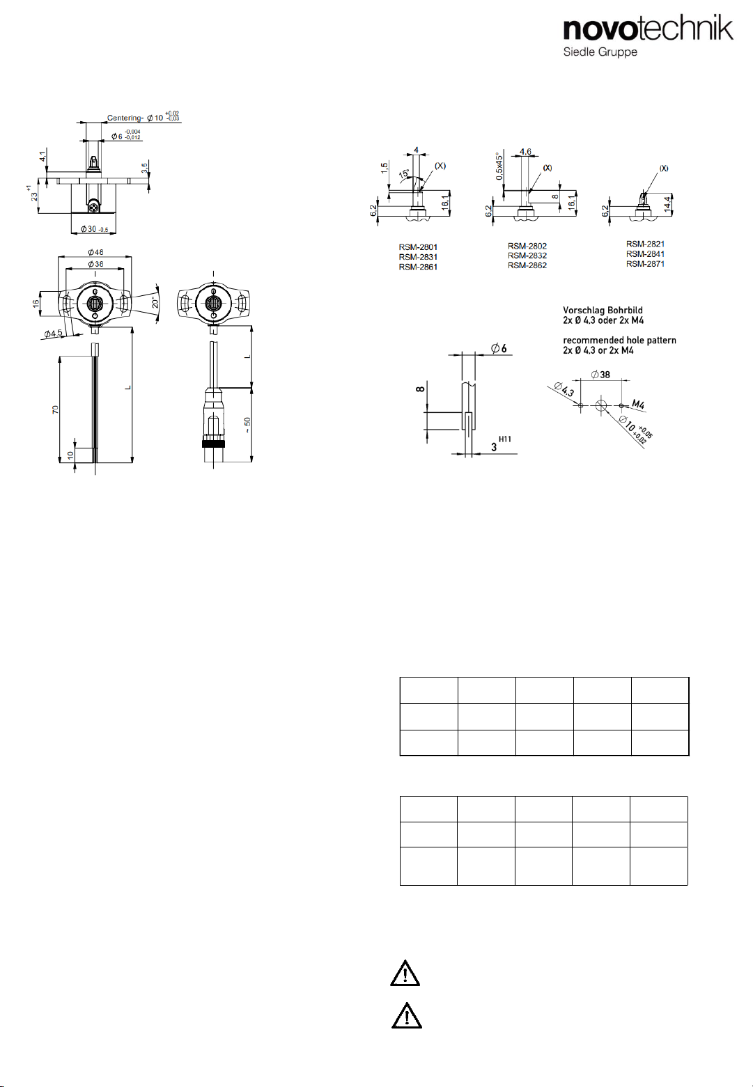
RSM-2800 Analogvarianten / Versions with analog interface
RSM-2800 Montageanleitung
RSM-2800 Users Manual
Änderungen vorbehalten / subject of change
P/N: 402518102_14
2. Installation
3. Montagehinweise
Bei der Montage der Befestigungsschrauben M4 ist das
maximale Drehmoment (max. 300 Ncm) zu beachten. Der
Kabelschirm ist an Masse anzuschliessen.
Der Mindest-Biegeradius des Kabels beträgt 40mm. Dauernder
Zug auf das Anschlusskabel in jeglicher Richtung ist zu
vermeiden.
Wenn das Kabel im Gebrauch bewegt wird, muss das Kabel
durch geeignete Maßnahmen (Schelle o.ä.) nach dem Austritt
fixiert werden.
Versorgungsspannung / Supply voltage
RSM-28__-___-1__-___:24 VDC (18...30 VDC)
RSM-28__-___-2__-___:5 VDC (4,5...5,5 VDC)
Ausgangsspannung / Output voltage
RSM-28__-___-11_-___: 0,1..10V
RSM-28__-___-12_-___: 4..20mA
RSM-28__-___-21_-___: 0,25..4,75V ratiometrisch / ratiometric
RSM-28__-___-22_-___: 0,5..4,5V ratiometrisch / ratiometric
RSM-28__-___-__1-___: steigend / rising CW
RSM-28__-___-__2-___: steigend / rising CCW
RSM-28__-___-__3-___: steigend / rising CW / CCW
(2-kanalig / 2 channels)
Stromaufnahme / Current draw
typ. 30 mA ohne Last / without load
Kabel / Cable
Geschirmte Leitung 0,5mm², AWG20
Shielded cable with lead wires 0.5mm², AWG20
4. Elektrische Anschlüsse / Electrical connections
ACHTUNG ! Bei Verlängerung des Kabels ist auf
ausreichende Schirmdämpfung zu achten.
Anschluß Abgang M12 / Connection M12
CAUTION ! Extension of cable demands a
sufficient shielding.
3. Installation instructions
Respect maximum tightening torque (max. 300 Ncm) when
fastening down the M4 screws. Connect the shield to GND.
Minimum bending radius of the cable is 40mm. Avoid steady
tension on the cable in any direction.
If the cable is moving in the application, appropriate action is to
be taken to fix the cable after the outlet of the sensor (use of
fixation clamp or similar).
Wellenformen / shaft styles
Bei Verlängerung des Anschlusskabels über > 30m erlischt
die CE-Freigabe
Elongation of the cable beyond 30m will void the CE
approval
Seite/ Page 2
RSM-2800 Montageanleitung
RSM-2800 Users Manual
Anschluß Kabelabgang / Connection cable outlet
Pin Nr.
Pin #
1 2 3 4
Einkanalig
single
Versorgung/
supply
Ausgang/
output
Masse/
Ground
NC
Zweikanalig
redundant
Versorgung/
supply
Ausgang1/
output1
Masse/
Ground
Ausgang2/
output2
Farbe
color
grün/
green
weiss/
white
braun/
brown
gelb/
yellow
Einkanalig
single
Versorgung/
supply
Ausgang/
output
Masse/
Ground
NC
Zweikanalig
partly
redundant
Versorgung/
supply
Ausgang 1/
output 1
Masse/
Ground
Ausgang 2/
output 2
2. Einbau
Parallelversatz < 0,05 mm
Parallel offset < 0.05 mm
Empfohlene Gegenkontur der
Antriebswelle für
Recommended dimensions of
driving shaft for
RSC-2821/2841/2871
(X) = Wellenmarkierung / Shaft marking
Änderungen vorbehalten / subject of change
P/N: 402518102_14
Seite / Page 3
RMB-3600 Montageanleitung
RMB-3600 Users Manual
4.1 Ausgangssignal bei Messbereich 2… 14 Umdrehungen / Output signal with measuring range 2… 14 turns
4.2 Ausgangssignal bei Messbereich 15 oder 16 Umdrehungen / Output signal with measuring range 15 or 16 turns
0°
0 U
Messbereich / measuring range
Funktionsbereich = 5760°
Operational range = 5760°
max
min
-360°
-1U 720 … 5040°
2 … 14U 5400°
15U
Winkel / angle
Output
U = Umdrehung Nr.
turn N°.
output cw
Oberer Überdrehbereich
Upper overtravel range
2…14 Umdrehungen / 2…14 turns
Unterer Überdrehbereich
Lower overtravel range
0°
0U
output ccw
max
min
5760° (5400°)
16 U (15U)
Winkel / angle
output ccw
U = Umdrehung Nr.
turn N°.
output cw
Output
Oberer Überdrehbereich
Upper overtravel range
Unterer Überdrehbereich
Lower overtravel range
360° / 1U
6.3 Verhalten bei Überdrehung
Bei normalem Betrieb darf der Sensor nicht über seinen
Funktionsbereich von 16 Umdrehungen (s.o.) überdreht
werden, um eine Verschiebung der Kennlinie unter allen
Umständen zu vermeiden.
Sobald der Sensor seinen Messbereich verlässt, geht das
Ausgangssignal auf min bzw. max. Dies gilt für beide
Überdrehrichtungen und auch, wenn der Sensor nicht
bestromt wird.
Um in den Messbereich zurückzugelangen, muss die Welle
des Sensors solange in die entsprechende Richtung
zurückgedreht werden, bis der Ausgangswert > min oder
< max ist.
Beispiel: Ausgang: 0,1 ... 10 V, Kennlinie steigend cw
Wenn Ausgangswert Sensor permanent 10 V ist:
=> Sensor befindet sich im oberen Überdrehbereich
=> Maßnahme: verdrehen ccw bis Ausgang < 10 V
6.3 Behaviour when overturned
In normal operation, the sensor should not be
overturned exceeding his operational range of 16
turns (see above) to avoid a shifting of the output
curve under any circumstance.
If the sensor is leaving its measuring range, the output
goes to min or max. This applies to both directions of
rotation and if the sensor is not powered.
To return back into the measuring range, the sensor shaft
has to be turned back in the appropriate direction until the
output value is > min or < max.
Example: Output 0.1 ... 10 V, rising characteristic cw
If sensor output shows permanently 10 V:
=> Sensor is turned over the upper overtravel range
=> Action: turn ccw until output value < 10V
Funktionsbereich = 5760°
Operational range = 5760
Messbereich 15 oder 16 Umdrehungen
measuring range 15 or 16 turns

This manual suits for next models

9

Other Siedle Transducer manuals

Siedle novotechnik FTI Series User manual

Siedle

Siedle novotechnik FTI Series User manual

Siedle Novotechnik TLM Series User manual

Siedle

Siedle Novotechnik TLM Series User manual

Siedle novotechnik TX2 Series User manual

Siedle

Siedle novotechnik TX2 Series User manual

Siedle Novotechnik TLH Series User manual

Siedle

Siedle Novotechnik TLH Series User manual

Siedle Novotechnik LWH Series User manual

Siedle

Siedle Novotechnik LWH Series User manual

Siedle Novotechnik TX2 Series User manual

Siedle

Siedle Novotechnik TX2 Series User manual

Siedle Novotechnik TP1 CANopen User manual

Siedle

Siedle Novotechnik TP1 CANopen User manual

Siedle novotechnik T Series User manual

Siedle

Siedle novotechnik T Series User manual

Siedle Novotechnik TH1 CANopen User manual

Siedle

Siedle Novotechnik TH1 CANopen User manual

Siedle Novotechnik TP1 CANopen User manual

Siedle

Siedle Novotechnik TP1 CANopen User manual

Siedle novotechnik RFC-4800 User manual

Siedle

Siedle novotechnik RFC-4800 User manual

Siedle Novotechnik LWG Series User manual

Siedle

Siedle Novotechnik LWG Series User manual

Siedle Novotechnik T Series User manual

Siedle

Siedle Novotechnik T Series User manual

Siedle Novotechnik TX2 User manual

Siedle

Siedle Novotechnik TX2 User manual

Siedle novotechnik PTN User manual

Siedle

Siedle novotechnik PTN User manual

Popular Transducer manuals by other brands

Knick VariTrans P 43000 TRMS user manual

Knick

Knick VariTrans P 43000 TRMS user manual

Texas Instruments PGA460-Q1 user guide

Texas Instruments

Texas Instruments PGA460-Q1 user guide

Simrad ES38-12 -  REV C Dimensions

Simrad

Simrad ES38-12 - REV C Dimensions

Simrad 200-7C -  REV B datasheet

Simrad

Simrad 200-7C - REV B datasheet

Garmin LIVESCOPE PLUS installation instructions

Garmin

Garmin LIVESCOPE PLUS installation instructions

promesstec UMU 500 user manual

promesstec

promesstec UMU 500 user manual

Lowrance Active Imaging 3-IN-1 installation manual

Lowrance

Lowrance Active Imaging 3-IN-1 installation manual

HyQuest Solutions WL3100 instruction manual

HyQuest Solutions

HyQuest Solutions WL3100 instruction manual

Balluff BTL7-A50 Series user guide

Balluff

Balluff BTL7-A50 Series user guide

HBM T4A Mounting instructions

HBM

HBM T4A Mounting instructions

Redback C 8856A operating instructions

Redback

Redback C 8856A operating instructions

Humminbird XHS 6 24 manual

Humminbird

Humminbird XHS 6 24 manual

LEM ITZ 2000-SPR FLEX ULTRASTAB manual

LEM

LEM ITZ 2000-SPR FLEX ULTRASTAB manual

SKF CMSS 785 Series user manual

SKF

SKF CMSS 785 Series user manual

NK TECHNOLOGIES VTR Series instructions

NK TECHNOLOGIES

NK TECHNOLOGIES VTR Series instructions

Thyracont VSM72 operating instructions

Thyracont

Thyracont VSM72 operating instructions

CCS WattNode Pulse WNB-3Y-208-P Installation and operation manual

CCS

CCS WattNode Pulse WNB-3Y-208-P Installation and operation manual

Woodward UMT 1 manual

Woodward

Woodward UMT 1 manual

manuals.online logo
manuals.online logoBrands
  • About & Mission
  • Contact us
  • Privacy Policy
  • Terms and Conditions

Copyright 2025 Manuals.Online. All Rights Reserved.