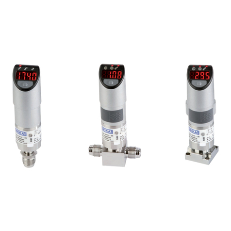
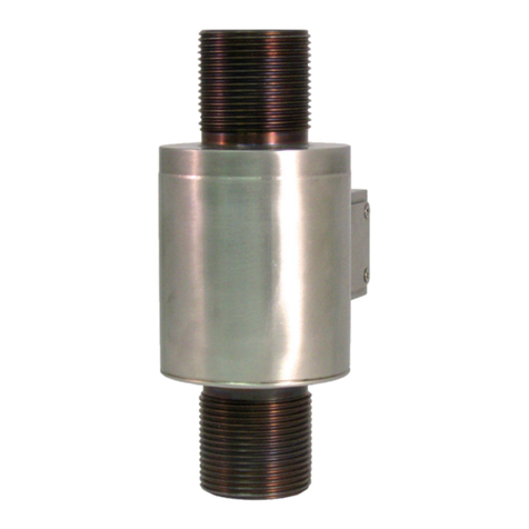
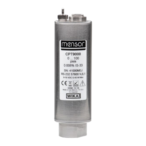
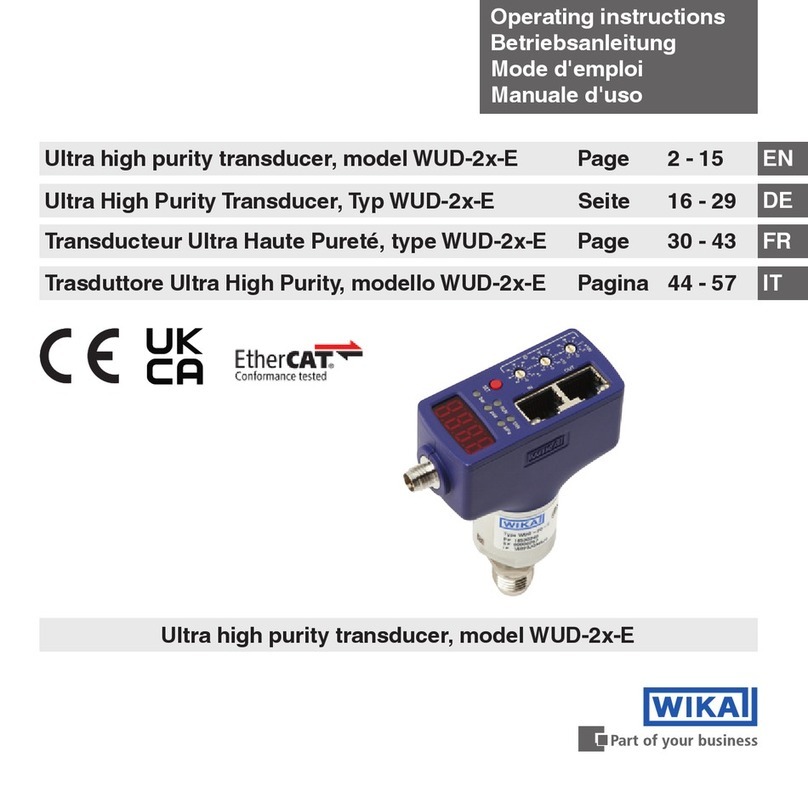
WIKA LSO.06 User manual

Operating instructions
Betriebsanleitung
Mode d'emploi
Manual de instrucciones
GB
D
F
E
Transducer model LSO.06 and
switching amplier model LSO.25
Messwandler Typ LSO.06 und
Schaltverstärker Typ LSO.25
Transducteur de mesure type LSO.06 et
relais amplicateur type LSO.25
Transductor modelo LSO.06 y
amplicador de conmutación modelo LSO.25
Switching amplier Transducer
model LSO.25 model LSO.06

2
13334603.01 09/2010 GB/D/F/E
WIKA operating instructions models LSO.06, LSO.25
GB
D
F
E
Operating instructions
Models LSO.06, LSO.25 Page 3 - 34
Betriebsanleitung
Typen LSO.06, LSO.25 Seite 35 - 66
Mode d'emploi
Types LSO.06, LSO.25 Page 67 - 98
Manual de instrucciones
Modelos LSO.06, LSO.25 Página 99 - 130
© WIKA Alexander Wiegand SE & Co. KG 2010
Prior to starting any work, read the operating instructions!
Keep for later use!
Vor Beginn aller Arbeiten Betriebsanleitung lesen!
Zum späteren Gebrauch aufbewahren!
Lire le mode d'emploi avant de commencer toute opération !
A conserver pour une utilisation ultérieure !
¡Leer el manual de instrucciones antes de comenzar cualquier trabajo!
¡Guardar el manual para una eventual consulta posterior!

WIKA operating instructions models LSO.06, LSO.25 3
13334603.01 09/2010 GB/D/F/E
Contents
1. General information 4
2. Safety 5
3. Specications 10
4. Design and function 13
5. Transport, packaging and storage 19
6. Commissioning, operation 20
7. Conguration 26
8. Notes for mounting and operating in hazardous
areas 30
9. Maintenance, repair and cleaning 30
10. Faults 32
11. Warranty 33
12. Dismounting, return and disposal 33
GB
Contents

4 WIKA operating instructions models LSO.06, LSO.25
13334603.01 09/2010 GB/D/F/E
1. General information
GB
1. General information
■
The instruments described in the operating instructions has been manufactured using
state-of-the-art technology.
All components are subject to stringent quality and environmental criteria during
production. Our management systems are certied to ISO 9001 and ISO 14001.
■
These operating instructions contain important information on handling the instrument.
Working safely requires that all safety instructions and work instructions are observed.
■
Observe the relevant local accident prevention regulations and general safety
regulations for the instrument's range of use.
■
The operating instructions are part of the instrument and must be kept in the immediate
vicinity of the instrument and readily accessible to skilled personnel at any time.
■
Skilled personnel must have carefully read and understood the operating instructions,
prior to beginning any work.
■
The manufacturer‘s liability is void in the case of any damage caused by using the
product contrary to its intended use, non-compliance with these operating instructions,
assignment of insuciently qualied skilled personnel or unauthorised modications to
the instrument
■
The general terms and conditions, contained in the sales documentation, shall apply.
■
Subject to technical modications.
■
Further information:
- Internet address: www.wika.de / www.wika.com
- Relevant data sheet: LM 31.10, LM 31.20
- Application consultant: Tel.: (+49) 9372/132-0
Fax: (+49) 9372/132-406
E-Mail: info@wika.de
Explanation of symbols
WARNING!
... indicates a potentially dangerous situation, which can result in serious
injury or death, if not avoided.
CAUTION!
... indicates a potentially dangerous situation, which can result in light
injuries or damage to equipment or the environment, if not avoided.

WIKA operating instructions models LSO.06, LSO.25 5
13334603.01 09/2010 GB/D/F/E
1. General information / 2. Safety
GB
Information
... points out useful tips, recommendations and information for ecient and
trouble-free operation.
DANGER!
...identies hazards caused by electric power. Should the safety instructions
not be observed, there is a risk of serious or fatal injury.
WARNING!
... indicates a potentially dangerous situation in a potentially explosive
atmosphere, resulting in serious injury or death, if not avoided.
2. Safety
WARNING!
Before installation, commissioning and operation, ensure that the
appropriate instrument has been selected in terms of measuring range,
design and specic measuring conditions.
Serious injuries and/or damage can occur should these not be observed.
Further important safety instructions can be found in the individual chapters
of these operating instructions.
2.1 Intended use
The model LSO.06 transducer is used for limit value detection in liquids. The
model LSO.25 switching amplier may be used in conjunction with the model LSO.06
transducer for overow control. The instruments are very robust and designed for rough
operating conditions.
These instruments have been designed and built solely for the intended use described
here, and may only be used accordingly.
The technical specications contained in these operating instructions must be observed.
Improper handling or operation of the transducer and the switching amplier outside of its
technical specications requires the instrument to be shut down immediately and inspect-
ed by an authorised WIKA service engineer.
The manufacturer shall not be liable for claims of any type based on operation contrary to
the intended use.

6 WIKA operating instructions models LSO.06, LSO.25
13334603.01 09/2010 GB/D/F/E
2. Safety
GB
2.2 Personnel qualication
WARNING!
Risk of injury should qualication be insucient!
Improper handling can result in considerable injury and damage to
equipment.
■
The activities described in these operating instructions may only be
carried out by skilled personnel who have the qualications described
below.
■
Keep unqualied personnel away from hazardous areas.
Skilled personnel
Skilled personnel are understood to be personnel who, based on their technical training,
knowledge of measurement and control technology and on their experience and
knowledge of country-specic regulations, current standards and directives, are capable
of carrying out the work described and independently recognising potential hazards.
Special operating conditions require further appropriate knowledge, e.g. of aggressive
media.
2.3 Additional safety instructions for instruments with ATEX approval
WARNING!
■
Non-observance of these instructions and their contents may result in the
loss of explosion protection
■
Observe the European Use Directive (EN 60 079-10:1996 )
2.4 Special hazards
WARNING!
Observe the information given in the applicable type examination certicate
and the relevant country-specic regulations for installation and use
in potentially explosive atmospheres (e.g. IEC 60079-14, NEC, CEC).
Non-observance can result in serious injury and/or damage to equipment.
For additional important safety instructions for insturments with ATEX
approval see chapter "2.3 Additional safety instructions for instruments with
ATEX approval".
WARNING!
For hazardous media such as oxygen, acetylene, ammable or toxic gases
or liquids, and refrigeration plants, compressors, etc., in addition to all
standard regulations, the appropriate existing codes or regulations must also
be followed.

WIKA operating instructions models LSO.06, LSO.25 7
13334603.01 09/2010 GB/D/F/E
2. Safety
GB
WARNING!
To ensure safe working on the instrument, the operating company must
ensure
■
that suitable rst-aid equipment is available and aid is provided whenever
required.
■
that the operating personnel are regularly instructed in all topics regarding
work safety, rst aid and environmental protection and knows the
operating instructions and, in particular, the safety instructions contained
therein.
DANGER!
Danger of death caused by electric current
Upon contact with live parts, there is a direct danger of death.
■
Electrical instruments may only be installed and mounted by skilled
electrical personnel.
■
Operation using a defective power supply unit (e.g. short circuit from the
mains voltage to the output voltage) may result in life-threatening voltages
on the instrument!
WARNING!
Residual media in dismounted instruments may result in a risk to people, the
environment and the system. Take sucient precautionary measures.
Do not use this instrument in safety or Emergency Stop devices. Incorrect
use of the instrument can result in injury.
Should a failure occur, aggressive media with extremely high temperature
and under high pressure or vacuum may be present at the instrument.

8 WIKA operating instructions models LSO.06, LSO.25
13334603.01 09/2010 GB/D/F/E
2. Safety
GB
2.5 Labelling / safety marks
Product label
■
Transducer model LSO.06
In mounted case
19" plug-in card
Model
Date of manufacture
For an explanation of
symbols see page 9
Model
■
Switching amplier model LSO.25
Date of manufacture
For an explanation
of symbols see
page 9

WIKA operating instructions models LSO.06, LSO.25 9
13334603.01 09/2010 GB/D/F/E
2. Safety
GB
Explanation of symbols
Before mounting and commissioning the instrument, ensure you read
the operating instructions!
CE, Communauté Européenne
Instruments bearing this mark comply with the relevant European directives.
ATEX European Explosion Protection Directive
(Atmosphère = AT, explosible = Ex)
Instruments bearing this mark comply with the requirements of the European
Directive 94/9/EC (ATEX) on explosion protection.

10 WIKA operating instructions models LSO.06, LSO.25
13334603.01 09/2010 GB/D/F/E
3. Specications
GB
3. Specications
3.1 Transducer model LSO.06
General data
Measuring accuracy ±0.5 mm
Ambient light max. 100 Lux
Mounting position any
Weight
■
Standard version
■
High and low temperature version
0.77 kg +9.3 g/cm ML 1)
1.07 kg +9.3 g/cm ML 1)
1) ML = Measuring length
Design data
Medium temperature
■
Standard version
■
High and low temperature version
-65 ... +250 °C
-269 ... +400 °C
Ambient temperature -65 ... +95 °C
Working pressure 0 ... 25 MPa (0 ... 250 bar)
High pressure version 0 ... 50 MPa (0 ... 500 bar)
Materials
■
Sensor case
■
Light guide
■
Packing
■
Case
1.4571 (option: hastelloy, other materials on request)
clad core glass (option: quartz, sapphire (only max.
ML = 60 mm))
graphite
stainless steel
Ex ignition protection type II 1/2 G Ex ib op is IIC T5, T6
T6: to 60 °C, T5: to 75 °C
ZELM 10 ATEX 0440
Electrical data
Cable gland M20 x 1.5, Ex: blue
Terminal connection 3 x 2.5 mm²
Ingress protection IP 65 per EN 60529
For further specications see WIKA data sheet LM 31.10 and the order documentation.

WIKA operating instructions models LSO.06, LSO.25 11
13334603.01 09/2010 GB/D/F/E
GB
Derating Diagram
(Temperature limitation of application)
Working pressure in bar
Medium temperature in °C
Ambient temperature in °C
P-T Diagram
(Pressure / temperature limitation of application)
for mounting connection G ½ A per DIN 910
Medium temperature in °C
Standard version
High temperature version
Low temperature version
Standard version
High temperature
version
3. Specications

12 WIKA operating instructions models LSO.06, LSO.25
13334603.01 09/2010 GB/D/F/E
GB
3.2 Switching amplier model LSO.25
General data
Functions
■
Selectable alarm direction
■
On-delay and drop-out delay for signal relay, each
adjustable up to approx. 8 s
Monitoring
■
Wire break signal circuit
■
Short-circuit signal circuit
■
Internal supply voltage, fail-safe
Weight
■
19" plug-in card
■
mounted case
0.31 (0.36) kg
0.6 (0.73) kg
Design data
Ambient temperature
■
19" plug-in card
■
mounted case
-25 ... +60 °C
-40 ... +40 °C
Ex ignition protection type II (2) G [Ex ib] IIC
ZELM 10 ATEX 0441
Maximum external inductance Lmax 0.5 mH
Maximum external capacitance Cmax 3 µF
U0≤ 9.6 V
I0≤ 149 mA
P0≤ 1.0 W
Electrical data
Supply voltage AC 230/115/120/24 V / DC 24 V
Power consumption 2.8 VA/3 W
Outputs
■
Signal relay, SPDT, 250 V/3 A/100 VA
■
Failure relay, SPDT, 250 V/3 A/100 VA
Cable glands M16 x 1.5 / M20 x 1.5 Ex: blue
Max. connection cross section 2.5 mm²
Cable length 175 ... 600 m (0.5 ... 1.5 mm²)
Ingress protection
■
19" plug-in card
■
mounted case
IP 20 per EN 60529
IP 65 per EN 60529
For further specications see WIKA data sheet LM 31.20 and the order documentation.
3. Specications

WIKA operating instructions models LSO.06, LSO.25 13
13334603.01 09/2010 GB/D/F/E
4. Design and function
GB
4. Design and function
4.1 Description
The transducer is used for measuring liquid level limits.
The conical tip of the sensor ensures really precise on-off performance level sensing.
Its reaction is independent of various physical parameters of the liquid such as density,
dielectric constant, conductivity, colour or refractive index. This allows the use for safe
level switching as well as for precise level control applications. If there is any foam you
even can decide whether to use the sensor for foam level or liquid level control, suppress-
ing the influence of foam on switching.
If the sensor is supplied with a U-tip, it is able to sense changes in refractive index. So it
can be used for example as an interface level switch for liquids.
Application range
Principle of operation
Separation layer, U-tip
e.g. oil
e.g. water
Principle of operation
Level, conical tip
Gas
Liquid
Working pressure in bar Working pressure in bar
Medium temperature in °C
Standard pressure version
without heatsink
threaded connection
High pressure
version with
heatsink
threaded
connection NPT ½
High pressure
version with
heatsink
threaded
connection G ½ A
All typs of transducers need a switching ampliers model LSO.25 for power supply and
switch state signalling.

14 WIKA operating instructions models LSO.06, LSO.25
13334603.01 09/2010 GB/D/F/E
4. Design and function
GB
4.2 Instrument design
Each unit consists of a transducer and a controller (switch amplier). The transducer may
be of one-piece or multi-part design. Ex types are generally constructed as multi-part
types. Multi-part transducers can be equipped with a heat-sink to expand the temperature
range.
4.2.1 Transducer model LSO.06
■
Without extension
Fixed measuring length ML, no extension
possible. Protection ngers are part of the
sensor housing.
Light guide Ø 7
Sensor
body
Sensor
housing
*) 20 for high pressure sensor
■
With extension
Measuring length ML from 50 to 960 mm.
Extension tube screwed into sensor
housing.
Preferential measuring lengths:
50, 60, 80, 90, 100, 120, 150, 200, 300,
600 and 800 mm
Values between these can be delivered
using variable-length types
*) 20 for high pressure sensor

WIKA operating instructions models LSO.06, LSO.25 15
13334603.01 09/2010 GB/D/F/E
4. Design and function
GB
■
For increased temperature range
Extended temperature range with heatsink. This may be combined with xed ML 25
mm and with extended types.
*) 20 for high pressure sensor
heatsink
■
Fitted with ange
Design with ange from DN25 and
from PN6 or ANSI, all forms of the
sealing face. Explosion-protected
instruments are usually seal-welded
to the sensor component (in this case,
the hexagon is omitted).
Insertion length EL =
ML-ange thickness
alternative
seal weld
seal weld
EL from
sealing face
ange
ML from
sealing face
sensor

16 WIKA operating instructions models LSO.06, LSO.25
13334603.01 09/2010 GB/D/F/E
4. Design and function
GB
■
Designs for level and separation layer
Level measurement with conical tip and neck tube/thermowell, measuring
length ML 50 ... 960 mm
Level measurement with conical tip, xed measuring length ML 25 mm,
without neck tube
Separation layer measurement with U-tip, neck tube/thermowell,
measuring length ML 50 ... 960 mm
Separation layer measurement with U-tip, xed measuring length
ML 25 mm, without neck tube
4.2.2 Switching amplier model LSO.25
■
19" plug-in card
Trans-
ducer
Fuse
time delay on
time delay o
time delay
Supply
Failure
Signal

WIKA operating instructions models LSO.06, LSO.25 17
13334603.01 09/2010 GB/D/F/E
4. Design and function
GB
For explosion protected version please note the following
:
The amplier is designed as a plug-in card for a 19" plug-in card. The plug-in card alone
doesn't fulll the ingress protection IP 20 in accordance with EN 60529: 1991. It only is
intended for the installation into a suitable rack which guarantees the minimum ingress
protection IP 20. Not used plug-in places have if necessary to be covered with blind plates.
The distances and tracking distances particularly are between the individual plug-in cards
as well as the intrinsic safe and not intrinsic safe circuits, the requirements on the wiring as
well as the excess temperature and the dissipation power converted in the assemblies are
to take into account according to
EN 60079-11:2007
. To avoid mistakes, the switch ampli-
ers are provided with an encoding system. It has to be made sure that the counter-strip is
executed availably and identically in the 19" rack.
Default coding
Supply voltage
version Encoder-strip rack,
provided at these positions
with coding pins
Encoder-strip plug-in card,
provided at these positions with one
coding pin
AC 230 V B-C-D-E-F-G-H-J 1
AC 115/120 V A, C-D-E-F-G-H-J 2
AC 24 V A-B, D-E-F-G-H-J 3
DC 24 V A-B-C, E-F-G-H-J 4
Encoder-strip plug-in card
Encoder-strip rack
Example: AC 230 V supply voltage version
We exclusively recommend the use of suitable racks for the guarantee of the requirements
to WIKA.

18 WIKA operating instructions models LSO.06, LSO.25
13334603.01 09/2010 GB/D/F/E
4. Design and function
GB
Alternatively the coding can take place directly in the female connector (rack side) and the
associated male connector (switching amplier side) after the following coding plan:
The coding pin is inserted with a tool captive in the appropriate place in the female
connector and at the opposite side in the male connector is a drilling.
■
In mounted case
4.3 Scope of delivery
Cross-check scope of delivery with delivery note.
trans-
ducer
75 high
Fuse
M20 x 1.5 or
M16 x 1.5
time delay on
time delay o
time delay
Supply
Failure
Signal

WIKA operating instructions models LSO.06, LSO.25 19
13334603.01 09/2010 GB/D/F/E
5. Transport, packaging and storage
GB
5. Transport, packaging and storage
5.1 Transport
Check instrument for any damage that may have been caused by transport.
Obvious damage must be reported immediately.
5.2 Packaging
Do not remove packaging until just before mounting.
Keep the packaging as it will provide optimum protection during transport (e.g. change in
installation site, sending for repair).
5.3 Storage
Permissible conditions at the place of storage:
■
Storage temperature: -25 ... +70 °C
■
Humidity: 35 ... 85 % relative humidity (no condensation)
Avoidance of exposure to the following factors:
■
Direct sunlight or proximity to hot objects
■
Mechanical vibration, mechanical shock (putting it down hard)
■
Soot, vapour, dust and corrosive gases
■
Potentially explosive environments, ammable atmospheres
Store the instrument in its original packaging in a location that fullls the conditions listed
above. If the original packaging is not available, package and store the instrument as
described below:
1. Wrap the instrument in an antistatic plastic lm.
2. Place the instrument, along with shock-absorbent material, in the packaging.
3. If stored for a prolonged period of time (more than 30 days), place a bag, containing a
desiccant, inside the packaging.
WARNING!
Before storing the instrument (following operation), remove any residual
media. This is of particular importance if the medium is hazardous to health,
e.g. caustic, toxic, carcinogenic, radioactive, etc.

20 WIKA operating instructions models LSO.06, LSO.25
13334603.01 09/2010 GB/D/F/E
6. Commissioning, operation
GB
6. Commissioning, operation
Before the installation a check of the function can be carried out. The device attached
provisionally and the glass tip are one and from dived to this for the test in a glass with
liquid (adjustment if necessary, see chapter "7.2 Adjustment with CAL").
WARNING!
The electrical connection only be carried out by qualied skilled personnel.
Observe the appropriate VDE regulations.
6.1 Installation instructions transducer model LSO.06
The sensors may be installed in any direction, i. e. from top, bottom, sideways or inclined.
In some special applications it is recommended to use following hints:
■
High viscosity: sideways or from bottom
■
Dry Running protection for pumps:
if the pipes to or from the pump are installed
horizontally use top mounting for fast detection of
liquid
■
Overll prevention devices: usually vertically from above
■
Vertical installation
Installation model LSO.06 from top with ange
connection e. g. as overow control.
■
Insertion length EL from sealing face ange
■
DIN anges from DN25 PN6
■
ANSI anges
■
The sealing forms are freely selectable
Explosion-protected version:
■
Flanges seal-welded with the transducer
sensor component
■
If seal-welded: no hexagon on sensor
component
This manual suits for next models
1
Table of contents
Languages:
Other WIKA Transducer manuals
Popular Transducer manuals by other brands

Airmar
Airmar CM599LH Owner's guide and installation instructions

Endress+Hauser
Endress+Hauser Cerabar PMP23 operating instructions

Simrad
Simrad TRANSDUCER MOUNTING ARRANGEMENT - SCHEMA REV... manual

Aplisens
Aplisens PM-22 user manual

Endress+Hauser
Endress+Hauser Cerabar T PMP 13 technical information

Camille Bauer
Camille Bauer SINEAX U 554 operating instructions