TLM Gebrauchsanleitung
TLM Manual
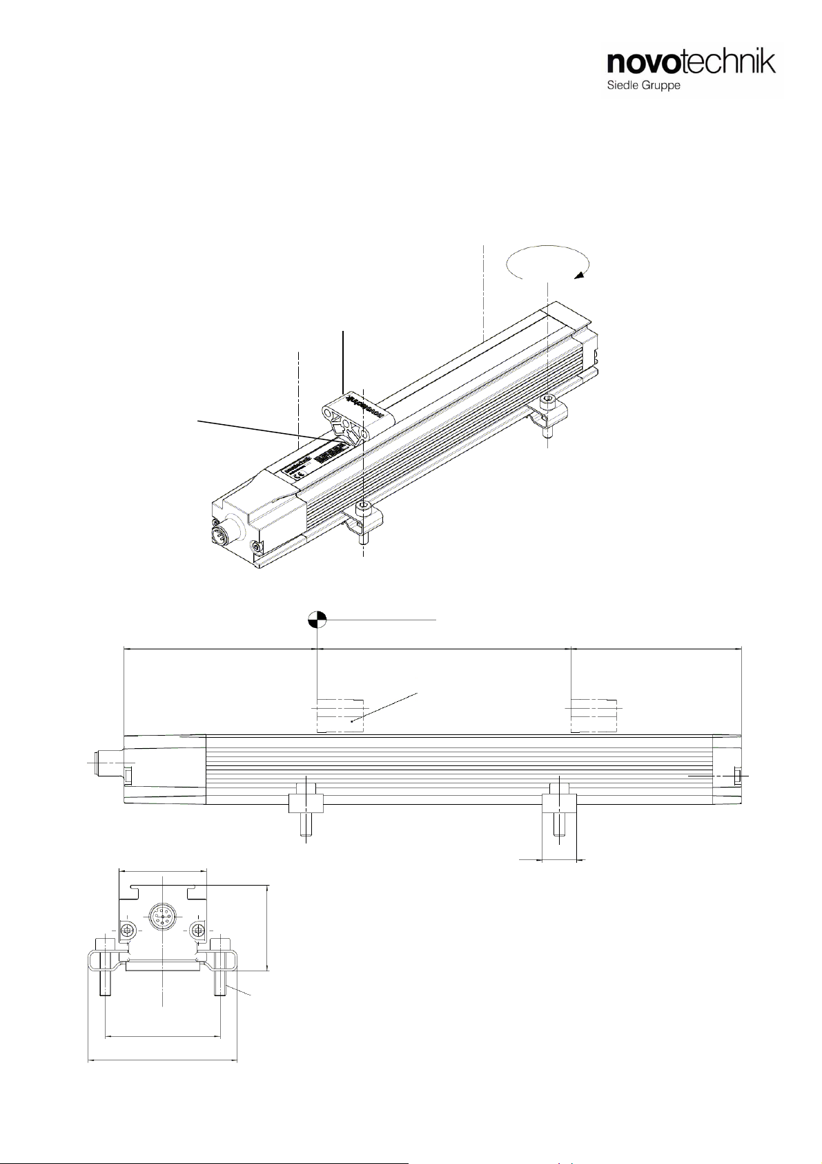
4Montagehinweis
Bei der Montage der Befestigungsklammern ist das
maximale Drehmoment von 200Ncm zu beachten.
Es wird empfohlen, die Befestigungsklammern in
gleichmäßigen Abständen zu platzieren.
Der Positionsgeber (Zubehör) wird im Abstand laut 6.2
zur Profiloberfläche montiert.
Die Aufnahme des Positionsgebers und die Befestigung
über Schrauben (M4) sollten über nichtmagnetisches
Material (z.B. Edelstahl, Messing, Aluminium) erfolgen.
Um die Genauigkeit des Wegaufnehmers zu gewährleisten,
muss der freie Positionsgeber parallel
zur Profiloberfläche geführt werden.
Der Betrieb mit Positionsgeber außerhalb des elektrischen
Messbereiches ist nicht zulässig!
Starke elektrische oder magnetische Felder in
unmittelbarer Nähe des Wegaufnehmers
können zu fehlerhaften Signalen führen.
Der Bereich für den Kabelabgang muss ausreichend
dimensioniert werden, der Mindestbiegeradius ist
einzuhalten und scharfe Kanten sind zu vermeiden!
Bei den Varianten mit mehreren Positionsgebern muss
der Abstand zwischen den Positionsgeber jeweils
min. 100 mm betragen!
Versatz des Positionsgebers:
Ein Höhenversatz des Positionsgebers Z-TLM-P01 von
0 - 4 mm bewirkt eine Signaländerung von ca. 200 µm/mm.
Ein Seitenversatz des Positionsgebers Z-TLM-P01 von
bis zu 2 mm führt zu keiner Signaländerung.
Ein Höhenversatz des Positionsgebers Z-TLM-P04 von
4 - 15 mm bewirkt eine Signaländerung von ca.
150 µm/mm.
Ein Seitenversatz des Positionsgebers Z-TLM-P04 von bis
zu 2 mm führt zu keiner Signaländerung, bei 2 -15 mm
beträgt die Signaländerung ca.15 µm/mm.
5Anschlüsse
Beim elektrischen Anschluss unbedingt zu beachten:
Anlage (Versorgung GND) und Schaltschrank (Signal GND)
müssen auf gleichem Potential liegen.
Um die elektromagnetische Verträglichkeit (EMV) zu
gewährleisten, sind nachfolgende Hinweise unbedingt zu
beachten:
• Wegaufnehmer und Steuerung müssen mit einem
geschirmten Kabel verbunden werden.
• Schirmung: Geflecht aus Kupfer-Einzeldrähten,
85% Bedeckung.
• Auf der Seite der Steuerung muss der Kabelschirm
geerdet, d.h. mit dem Schutzleiter verbunden werden.
Anschlusskabel darf nicht auf über 30m
verlängert werden!
4Instruction for installation
The maximum torque of 200Ncm is to be considered by
assembling of the mounting clamps.
It is recommended to place the mounting clamps in constant
distances.
The position marker (accessory) is installed at a distance to
the profile surface according to item 6.2.
For the mounting of the position marker and the fixing via
screws (M4) non-magnetic material (e.g. stainless steel,
brass, aluminum) should be used preferably.
In order to ensure the accuracy of the transducer, the floating
position marker must be guided parallel to the profile surface.
Operating with position marker outside of the electrical
measuring range is not allowed!
Strong electrical or magnetic fields in the
immediate vicinity of the transducer may lead to
faulty signals.
For the area of the cable please take care that enough space
is available, the minimum bending radius has been observed
and sharp edges have be avoided!
For the versions with several position markers the distance
between the position markers must be
min. 100 mm!
Displacement of the position marker:
A horizontal displacement of the position marker Z-TLM-P01
of 0 - 4 mm causes a change of signal of approx.
200 µm/mm.
A vertical displacement of the position marker Z-TLM-P01 of
up to 2 mm leads to no change of signal.
A horizontal displacement of the position marker Z-TLM-P04
of 4 - 15 mm causes a change of signal of approx.
150 µm/mm.
A vertical displacement of the position marker Z-TLM-P04
of up to 2 mm leads to no change of signal, from 2 - 15 mm
the change of signal amounts to approx.15 µm/mm.
5 Wiring
Note the following when making electrical connection:
System (supply voltage GND) and control cabinet (signal
GND) must be at the same potential.
To ensure the electromagnetic compatibility (EMC), the
following instructions must be strictly followed:
• Transducer and controller must be connected by using a
shielded cable.
• Shielding: Copper filament braided, 85% coverage.
• On the controller side the cable shield must be grounded,
i.e. be connected with the protective earth conducter.
Cable connection may not extended over 30m!
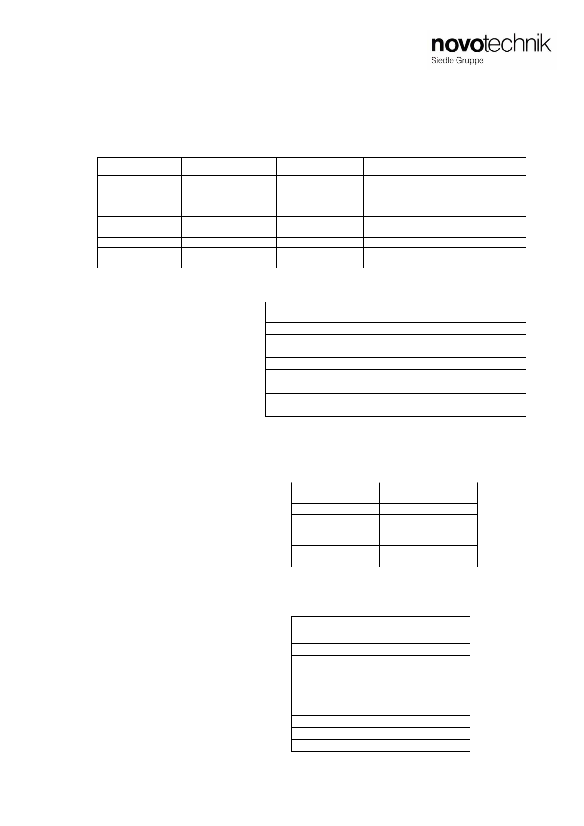
3Elektrische Daten / Electrical data
Versorgungsspannung / Supply voltage: 24 VDC (siehe auch Datenblatt / see also data sheet)
Stromaufnahme / Current draw: ≤100 mA typisch / typical
Artikelnummer / Item number: 515748/06 Änderungen vorbehalten / Subject to change without notice 2012/02 Seite / page 2