Siei ARTDriveG User manual

.....Instruction Manual
ARTDriveG
General-PurposeInverter
230/400/460V Class
575VClass
ARTDriveG

Thank you for choosing this SIEI product.
We will be glad to receive any possible information which could help us improving this manual. The e-mail address is the
following:[email protected] .
Before using the product, read the safety instruction section carefully.
Keepthemanualinasafe placeandavailableto engineeringandinstallationpersonnel duringtheproductfunctioning period.
SIEI S.p.A has the right to modify products, data and dimensions without notice.
The data can only be used for the product description and they can not be understood as legally stated properties.
Thismanualisupdatedaccordingto firmware version V03.02.
Allrightsreserved

ARTDriveG Instruction Manual Table of Contents • 3
Table of Contents
Safety Symbol Legend - Precautions de securité...................................................................... 6
Chapter 1 - Safety Precautions..................................................................................................7
1.1PowerSupplyandGrounding ........................................................................................................................................................ 10
Chapter 2 - General................................................................................................................... 11
Features ............................................................................................................................................................................................12
Accessories/Options ........................................................................................................................................................................12
Chapter 3 - Inspection Procedure, Component Identification and Standard Specification .... 13
3.1UponDeliveryInspectionProcedures............................................................................................................................................ 13
3.1.1General .....................................................................................................................................................................................13
3.1.2InverterTypeDesignation ..........................................................................................................................................................13
3.1.3Nameplate ................................................................................................................................................................................14
3.2ComponentIdentification .............................................................................................................................................................. 15
3.3StandardSpecifications ................................................................................................................................................................ 16
3.3.1PermissibleEnvironmentalConditions .......................................................................................................................................16
Disposalof the Device ...............................................................................................................................................................17
3.3.2MainsConnectionandInverterOutput .......................................................................................................................................17
3.3.3ACInputCurrent ........................................................................................................................................................................20
3.3.4ACOutput..................................................................................................................................................................................20
3.3.5Open-LoopandClosed-LoopControlSection ..............................................................................................................................21
3.3.6Accuracy ..................................................................................................................................................................................21
Chapter 4 - Installation Guidelines ........................................................................................... 23
4.1MechanicalSpecification.............................................................................................................................................................. 23
4.2WattsLoss,HeatDissipation,InternalFansandMinimumCabinetOpeningSuggestedfortheCooling ........................................ 27
4.2.1CoolingFansPowerSupply.......................................................................................................................................................28
4.3InstallationMountingClearance.................................................................................................................................................... 29
4.4MotorsandEncoder ...................................................................................................................................................................... 30
4.4.1.ACInductionMotors.................................................................................................................................................................30
4.4.2Encoder ....................................................................................................................................................................................31
Chapter 5 - Wiring Procedure................................................................................................... 33
5.1AccessingtotheConnectors ........................................................................................................................................................ 33
5.2PowerSection .............................................................................................................................................................................. 35
5.2.1MaximumCableCrossSectionforPowerTerminals ..................................................................................................................36
5.2.2 RectificationandIntermediate(D.C.)Circuit ..............................................................................................................................37
5.2.3Inverter .....................................................................................................................................................................................38
5.3RegulationSection ........................................................................................................................................................................ 39
5.3.1R-AGyRegulationCard..............................................................................................................................................................39
5.3.2TerminalAssignmentsonRegulationSection .............................................................................................................................40
5.4SerialInterface ............................................................................................................................................................................. 41
5.4.1InGeneral .................................................................................................................................................................................41
5.4.2RS485SerialInterfaceConnectorDescription...........................................................................................................................42
5.5Typical ConnectionDiagrams ........................................................................................................................................................ 43
5.5.1AGyConnection ........................................................................................................................................................................43
5.5.2EngineeringNotes .....................................................................................................................................................................44
5.5.3.ParallelConnectionontheAC(Input)andDC(IntermediateCircuit)SideofSeveralInverters ...................................................45
5.6CircuitProtection .......................................................................................................................................................................... 46
5.6.1ExternalFusesofthePowerSection ..........................................................................................................................................46
5.6.2 ExternalFusesofthePowerSectionDCInputSide....................................................................................................................47
5.6.3InternalFuses............................................................................................................................................................................48
5.7Chokes/Filters(Optional) ............................................................................................................................................................ 48
5.7.1ACInputChokes ........................................................................................................................................................................49
5.7.2OutputChokes ...........................................................................................................................................................................49

4 • Table of Contents ARTDriveG Instruction Manual
5.7.3InterferenceSuppressionFilters ................................................................................................................................................50
5.7.3.1EMIfilterconnectionsforSizes1007...3150(230V...480V) ..............................................................................................52
5.7.3.2EMIfilterconnectionsforSizes4220...71320(230V...480V).............................................................................................53
5.8BrakingintheAGySystem ........................................................................................................................................................... 54
5.8.1BrakingUnit ..............................................................................................................................................................................54
5.8.1.1ExternalBrakingResistor ...............................................................................................................................................56
5.8.2D.C.Braking ..............................................................................................................................................................................59
5.9DischargeTimeoftheDC-Link ..................................................................................................................................................... 59
Chapter 6 - Drive Keypad Operation......................................................................................... 60
6.1Keypad ......................................................................................................................................................................................... 60
6.2LanguageSelection ....................................................................................................................................................................... 62
6.3MovingThroughtheDriveMainMenu .......................................................................................................................................... 62
6.4Scrolling ThroughtheDrive Parameters ........................................................................................................................................ 63
6.5ParametersModification .............................................................................................................................................................. 63
6.6QuickstartProcedure .................................................................................................................................................................... 64
Chapter 7 - Parameter Description .......................................................................................... 65
7.1ParametersList ............................................................................................................................................................................ 65
7.2 Menud-DISPLAY ....................................................................................................................................................................... 92
Basic.................................................................................................................................................................................................92
Overload............................................................................................................................................................................................92
Inputs/Outputs....................................................................................................................................................................................93
Encoder.............................................................................................................................................................................................96
Option................................................................................................................................................................................................97
Pid ....................................................................................................................................................................................................97
Alarmlist...........................................................................................................................................................................................98
DriveIdentification.............................................................................................................................................................................98
Utility.................................................................................................................................................................................................99
7.3 MenuS-START-UP....................................................................................................................................................................100
PowerSupply.................................................................................................................................................................................. 100
V/F Characteristic........................................................................................................................................................................... 100
MotorData ...................................................................................................................................................................................... 101
Commands&Referencies ................................................................................................................................................................ 102
Functions......................................................................................................................................................................................... 104
Utility............................................................................................................................................................................................... 105
7.4 MenuI-INTERFACE...................................................................................................................................................................106
DigitalInputsRegulationBoard ........................................................................................................................................................ 106
DigitalInputsExpansionBoard ......................................................................................................................................................... 107
DigitalOuputsRegulationBoard ....................................................................................................................................................... 108
DigitalOutputsExpansionBoard ....................................................................................................................................................... 109
AnalogInputsRegulationBoard ....................................................................................................................................................... 110
AnalogOutputsRegulationBoard ..................................................................................................................................................... 114
AnalogOutputsExpBoard ................................................................................................................................................................ 117
EnablingVirtualI/O .......................................................................................................................................................................... 118
EncoderConfiguration...................................................................................................................................................................... 122
SerialConfiguration ......................................................................................................................................................................... 123
OptionsConfiguration....................................................................................................................................................................... 125
SBIConfiguration............................................................................................................................................................................. 126
7.5 Menu F-FREQ&RAMPS ...........................................................................................................................................................128
Motorpotentiometer ......................................................................................................................................................................... 128
ReferenceLimits .............................................................................................................................................................................. 130
ReferenceSources .......................................................................................................................................................................... 131
MultispeedFunction ........................................................................................................................................................................ 132
RampConfiguration ......................................................................................................................................................................... 134
JumpFrequencies ........................................................................................................................................................................... 136
7.6 MenuP-PARAMETERS..............................................................................................................................................................138
Commands ...................................................................................................................................................................................... 138
PowerSupply.................................................................................................................................................................................. 144
MotorData ...................................................................................................................................................................................... 144
V/F Curve ........................................................................................................................................................................................ 145

ARTDriveG Instruction Manual Table of Contents • 5
OuputFrequencyLimit ..................................................................................................................................................................... 147
SlipCompensation........................................................................................................................................................................... 147
Boost............................................................................................................................................................................................... 148
AutomaticFluxRegulation................................................................................................................................................................ 149
AntiOscillationFunction .................................................................................................................................................................. 149
SWCurrentClamp........................................................................................................................................................................... 149
CurrentLimit .................................................................................................................................................................................... 150
DCLinkLimit .................................................................................................................................................................................... 152
OverTorqueAlarmConfiguration...................................................................................................................................................... 153
MotorOverloadConfiguration .......................................................................................................................................................... 154
BUConfiguration.............................................................................................................................................................................. 154
DCBrakeConfiguration .................................................................................................................................................................... 155
Autocapturefunction........................................................................................................................................................................ 156
UndervoltageConfiguration.............................................................................................................................................................. 158
OvervoltageConfiguration................................................................................................................................................................ 162
AutoresetConfiguration.................................................................................................................................................................... 163
ExternalFaultConfiguration ............................................................................................................................................................. 164
PhaseLossDetection ....................................................................................................................................................................... 164
VoltageReductionConfiguration ...................................................................................................................................................... 165
FrequencyThreshold ....................................................................................................................................................................... 166
SteadyStateSignalling.................................................................................................................................................................... 168
HeatsinkTemperatureThreshold....................................................................................................................................................... 168
PWMSetting................................................................................................................................................................................... 169
DeadTimeCompensation................................................................................................................................................................. 170
DisplaySetting ................................................................................................................................................................................ 170
Protection........................................................................................................................................................................................ 171
7.7 MenuA- APPLICATION .............................................................................................................................................................172
PIDSetting ...................................................................................................................................................................................... 172
PIDGains......................................................................................................................................................................................... 176
PIDLimits ........................................................................................................................................................................................ 176
7.8 MenuC-COMMANDS...............................................................................................................................................................181
Basic............................................................................................................................................................................................... 181
AlarmRegisterReset ....................................................................................................................................................................... 181
ExternalKey .................................................................................................................................................................................... 181
Tuning ............................................................................................................................................................................................. 182
7.9 MenuH- HIDDEN ......................................................................................................................................................................183
VirtualI/OCommands ...................................................................................................................................................................... 183
ProfidriveParameters...................................................................................................................................................................... 184
DriveStatus..................................................................................................................................................................................... 185
ParametersReadingExtension ......................................................................................................................................................... 185
RemoteI/OsControl ......................................................................................................................................................................... 186
SerialLinkCommands...................................................................................................................................................................... 187
Chapter 8 - Serial Protocol ..................................................................................................... 189
8.1ModbusRTUProtocolforAGydrives...........................................................................................................................................189
8.1.1Introduction............................................................................................................................................................................. 189
8.1.2TheMODBUSProtocol ............................................................................................................................................................ 189
8.1.3Messageformat ...................................................................................................................................................................... 189
8.1.3.1Theaddress ................................................................................................................................................................... 189
8.1.3.2Thefunctioncode........................................................................................................................................................... 189
8.1.3.3CRC16 ............................................................................................................................................................................ 190
8.1.3.4Messagesynchronization .............................................................................................................................................. 190
8.1.3.5Serial line setting........................................................................................................................................................... 190
8.1.4Modbusfunctionsforthedrive ................................................................................................................................................ 191
8.1.4.1ReadOutputRegisters(03) ............................................................................................................................................ 191
8.1.4.2ReadInputRegisters(04) .............................................................................................................................................. 191
8.1.4.3PresetSingleRegister (06) ............................................................................................................................................ 192
8.1.4.4ReadStatus(07)............................................................................................................................................................ 192
8.1.4.5PresetMultiple Registers (16) ....................................................................................................................................... 193
8.1.5Errormanagement................................................................................................................................................................... 193
8.1.5.1Exceptioncodes ............................................................................................................................................................ 194
8.1.6Systemconfiguration............................................................................................................................................................... 194
8.2Proprietaryprotocol .....................................................................................................................................................................195

6 • Table of Contents ARTDriveG Instruction Manual
Safety Symbol Legend - Precautions de securité
Indicates a procedure, condition, or statement that, if not strictly observed, could result in perso-
nal injury or death.
Indique le mode d'utilisation, la procédure et la condition d'exploitation. Si ces consignes ne sont pas
strictement respectées, il y a des risques de blessures corporelles ou de mort.
Indicatesa procedure, condition, or statement that, if not strictlyobserved, could result in damage
to or destruction of equipment.
Indique et le mode d'utilisation, la procédure et la condition d'exploitation. Si ces consignes ne sont pas
strictement respectées, il y a des risques de détérioration ou de destruction des appareils
Indicates a procedure, condition, or statement that should be strictly followed in order to optimize
these applications.
Indique le mode d'utilisation, la procédure et la condition d'exploitation. Ces consignes doivent être
rigoureusementrespectéespour optimiser ces applications..
Warning!
Caution
Attention
NOTE!Indicatesan essential or important procedure, condition,or statement.
Indiqueunmode d'utilisation, de procédure etde condition d'exploitation essentiels ouimportants
8.2.1Introduction............................................................................................................................................................................. 195
8.2.2Messageformat ...................................................................................................................................................................... 195
8.2.3Address................................................................................................................................................................................... 196
8.2.4Controlcode ........................................................................................................................................................................... 196
8.2.5Functions ................................................................................................................................................................................ 196
8.2.6MsgSlavemeaning ................................................................................................................................................................ 197
Chapter 9 - Troubleshooting ................................................................................................... 199
9.1Drive AlarmCondition ..................................................................................................................................................................199
9.2AlarmReset.................................................................................................................................................................................199
9.3ListofDriveAlarmEvents ...........................................................................................................................................................200
Chapter 10 - EMC Directive, Declarations of EC-Conformity................................................ 201
Index Parameters ................................................................................................................... 204

ARTDriveG Instruction manual Chapter 1 - Safety • 7
Chapter 1 - Safety Precautions
Accordingto the EEC standards theARTDRiveG and accessories must beused only after checking
that the machine has been produced using those safety devices required by the 89/392/EEC set
ofrules, as faras the machine industryis concerned. These standardsdo not applyin the Americas,
but may need to be considered in equipment being shipped to Europe.
Drive systems cause mechanical motion. It is the responsibility of the user to insure that any
such motion does not result in an unsafe condition. Factory provided interlocks and operating
limits should not be bypassed or modified.
Selon les normes EEC, les drives ARTDRiveG et leurs accessoires doivent être employés seulement
après avoir verifié que la machine ait été produit avec les même dispositifs de sécurité demandés par la
réglementation 89/392/EEC concernant le secteur de l’industrie.
Les systèmes provoquent des mouvements mécaniques. L’utilisateur est responsable de la sécurité
concernantlesmouvements mécaniques. Les dispositifs desécuritéprévues par l’usine et les limitations
operationelles ne doivent être dépassés ou modifiés.
Electrical Shock and Burn Hazard:
When using instruments such as oscilloscopes to work on live equipment, the oscilloscope’s
chassis should be grounded and a differential amplifier input should be used. Care should be
used in the selection of probes and leads and in the adjustment of the oscilloscope so that
accurate readings may be made. See instrument manufacturer’s instruction book for proper
operation and adjustments to the instrument.
Décharge Èlectrique et Risque de Brúlure :
Lors de l’utilisation d’instruments (par example oscilloscope) sur des systémes en marche, le chassis de
l’oscilloscope doit être relié à la terre et un amplificateur différentiel devrait être utilisé en entrée.
Lessondes et conducteurs doivent être choissis avec soinpour effectuer les meilleures mesures à l’aide
d’un oscilloscope. Voir le manuel d’instruction pour une utilisation correcte des instruments.
Fire and Explosion Hazard:
Fires or explosions might result from mounting Drives in hazardous areas such as locations where
flammable or combustible vapors or dusts are present. Drives should be installed away from
hazardous areas, even if used with motors suitable for use in these locations.
Risque d’incendies et d’explosions:
L’utilisation des drives dans des zônes à risques (présence de vapeurs ou de poussières inflammables),
peut provoquer des incendies ou des explosions. Les drives doivent être installés loin des zônes
dangeureuses, et équipés de moteurs appropriés.
Strain Hazard:
Improper lifting practices can cause serious or fatal injury. Lift only with adequate equipment and
trained personnel.
Attention à l’Élévation:
Une élévation inappropriée peut causer des dommages sérieux ou fatals. Il doit être élevé seulement
avec des moyens appropriés et par du personnel qualifié.
Drives and motors must be ground connected according to the NEC.
Tous les moteurs et les drives doivent être misà la terreselon le CodeElectrique National ouéquivalent.
Replace all covers before applying power to the Drive. Failure to do so may result in death or
serious injury.
Remettre tous les capots avant de mettre sous tension le drive. Des erreurs peuvent provoquer de
sérieux accidents ou même la mort.
Adjustable frequency drives are electrical apparatus for use in industrial installations. Parts of the
Drivesareenergized duringoperation. Theelectrical installationandthe openingof thedevice should
therefore only be carried out by qualified personnel. Improper installation of motors or Drives may
therefore cause the failure of the device as well as serious injury to persons or material damage.
Driveisnotequippedwithmotoroverspeedprotectionlogicotherthanthatcontrolledbysoftware.Follow
the instructions given in this manual and observe the local and national safety regulations applicable.
Les drives à fréquence variable sont des dispositifs électriques utilisés dans des installations industriels.
Une partie des drives sont sous tension pendant l’operation. L’installation électrique et l’ouverture des
drives devrait être executé uniquement par du personel qualifié. De mauvaises installations de moteurs
Warning!

8 • Chapter 1 - Safety ARTDriveG Instruction manual
ou de drives peuvent provoquer des dommages materiels ou blesser des personnes.On doit suivir les
instructions donneés dans ce manuel et observer les régles nationales de sécurité.
Always connect the Drive to the protective ground (PE) via the marked connection terminals
(PE2) and the housing (PE1). AGy Drives and AC Input filters have ground discharge currents
greater than 3.5 mA. EN 50178 specifies that with discharge currents greater than 3.5 mA the
protective conductor ground connection (PE1) must be fixed type and doubled for redundancy.
Il faut toujours connecter le variateur à la terre (PE) par les des bornes (PE2) et le châssis (PE1). Le
courant de dispersion vers la terre est supérieur à 3,5 mA sur les variateurs Brushless et sur les filtres à
courant alterné (CA). Les normes EN 50178 spécifient qu'en cas de courant de dispersion vers la terre,
supérieur à 3,5 ma, la mise à la terre (PE1) doit avoir une double connexion pour la redondance.
The drive may cause accidental motion in the event of a failure, even if it is disabled, unless it has
been disconnected from the AC input feeder.
En cas de panne, le variateur peut causer une mise en marche accidentelle, même s'il est désactivé,
sauf s'il a été débranché de l'alimentateur à courant alterné.
Never open the device or covers while the AC Input power supply is switched on. Minimum time
to wait before working on the terminals or inside the device is listed in section 5.9 on Instruction
manual .
Nejamais ouvrir l’appareillorsqu’ilestsuns tension. Letempsminimumd’attente avant depouvoirtravailler
sur les bornes ou bien à l’intérieur de l’appareil est indiqué dans la section 5.9.
If the front plate has to be removed because of ambient temperature higher than 40 degrees, the
user has to ensure that no occasional contact with live parts may occur.
Si la plaque frontale doit être enlevée pour un fonctionnement avec la température de l’environnement
plushauteque40°C,l’utilisateurdoits’assurer, par des moyens opportuns, qu’aucun contactoccasionnel
ne puisse arriver avec les parties sous tension.
Do not connect power supply voltage that exceeds the standard specification voltage fluctuation
permissible. If excessive voltage is applied to the Drive, damage to the internal components will
result.
Ne pas raccorder de tension d’alimentation dépassant la fluctuation de tension permise par les normes.
Dansle casd’une alimentationentensionexcessive, descomposantsinternes peuventêtreendommagés.
Do not operate the Drive without the ground wire connected. The motor chassis should be grounded to
earth through a ground lead separate from all other equipment ground leads to prevent noise coupling.
Nepasfairefonctionnerledrivesansprisedeterre.Lechassisdumoteurdoit êtremisàlaterreàl’aided’un
connecteur de terre separé des autres pour éviter le couplage des perturbations. Le connecteur de terre
devrait être dimensionné selon la norme NEC ou le Canadian Electrical code.
The grounding connector shall be sized in accordance with the NEC or Canadian Electrical Code.
The connection shall be made by a UL listed or CSA certified closed-loop terminal connector
sized for the wire gauge involved. The connector is to be fixed using the crimp tool specified by
the connector manufacturer.
Le raccordement devrait être fait par un connecteur certifié et mentionné à boucle fermé par les
normes CSA et UL et dimensionné pour l’épaisseur du cable correspondant. Le connecteur doit être
fixé a l’aide d’un instrument de serrage specifié par le producteur du connecteur.
Do not perform a megger test between the Drive terminals or on the control circuit terminals.
Ne pas exécuter un test megger entre les bornes du drive ou entre les bornes du circuit de contrôle.
Because the ambient temperature greatly affects Drive life and reliability, do not install the
Drive in any location that exceeds the allowable temperature. Leave the ventilation cover
attached for temperatures of 104° F (40° C) or below.
Étant donné que la température ambiante influe sur la vie et la fiabilité du drive, on ne devrait pas
installer le drive dans des places ou la temperature permise est dépassée. Laisser le capot de
ventilation en place pour températures de 104°F (40°C) ou inférieures.
Warning!
Caution

ARTDriveG Instruction manual Chapter 1 - Safety • 9
If the Drive’s Fault Alarm is activated, consult the TROUBLESHOOTING section of this instruction
book, and after correcting the problem, resume operation. Do not reset the alarm automatically
by external sequence, etc.
Si la Fault Alarm du drive est activée, consulter la section du manuel concernant les défauts et après avoir
corrigél’erreur,reprendrel’opération.Nepasréiniliatiserl’alarmeautomatiquementparuneséquenceexterne,
etc.
Be sure to remove the desicant dryer packet(s) when unpacking the Drive. (If not removed these
packets may become lodged in the fan or air passages and cause the Drive to overheat).
Lorsdu déballage dudrive, retirer le sachet déshydraté. (Si celui-ci n’est pas retiré, il empêche laventilation
et provoque une surchauffe du drive).
The Drive must be mounted on a wall that is constructed of heat resistant material. While the
Drive is operating, the temperature of the Drive's cooling fins can rise to a temperature of 194° F
(90°C).
Le drive doit être monté sur un mur construit avec des matériaux résistants à la chaleur. Pendant le
fonctionnementdu drive, la température desailettes du dissipateur thermiquepeut arriver à 194°F(90°).
Do not touch or damage any components when handling the device. The changing of the isolation
gaps or the removing of the isolation and covers is not permissible.
Manipulerl’appareilde façon à ne pas toucher ou endommager des parties. Iln’estpaspermisdechanger
les distances d’isolement ou bien d’enlever des matériaux isolants ou des capots.
Protectthe device fromimpermissible environmentalconditions(temperature, humidity,shock etc.)
Protéger l’appareil contre des effets extérieurs non permis (température, humidité, chocs etc.).
No voltage should be connected to the output of the drive (terminals U2, V2 W2). The parallel connection
of several drives via the outputs and the direct connection of the inputs and outputs (bypass) are not
permissible.
Aucune tension ne doit être appliquée sur la sortie du convertisseur (bornes U2, V2 et W2). Il n’est pas
permisderaccorderlasortiede plusieurs convertisseurs en parallèle, ni d’effectuer une connexion directe
de l’entrée avec la sortie du convertisseur (Bypass).
A capacitative load (e.g. Var compensation capacitors) should not be connected to the output of
the drive (terminals U2, V2, W2).
Aucunecharge capacitive ne doit être connectée àlasortieduconvertisseur(bornesU2, V2 et W2) (par exemple
des condensateurs de mise en phase).
The electrical commissioning should only be carried out by qualified personnel, who are also
responsible for the provision of a suitable ground connection and a protected power supply
feeder in accordance with the local and national regulations. The motor must be protected against
overloads.
La mise en service électrique doit être effectuée par un personnel qualifié. Ce dernier est responsable de
l’existence d’une connexion de terre adéquate et d’une protection des câbles d’alimentation selon les
prescriptions locales et nationales. Le moteur doit être protégé contre la surcharge
No dielectric tests should be carried out on parts of the drive. A suitable measuring instrument
(internal resistance of at least 10 kΩΩ
ΩΩ
Ω//
//
/V) should be used for measuring the signal voltages.
Il ne faut pas éxécuter de tests de rigidité diélectrique sur des parties du convertisseurs. Pour mesurer les
tensions,des signaux, ilfaut utiliser desinstruments de mesure appropriés (résistance interne minimale 10
k
Ω
/V).
Caution
NOTE!Ifthe Drives havebeen stored for longer than twoyears, the operation of theDClink capacitors may be impaired
and must be “reformed”.
Before commissioning devices that have been stored for long periods, connect them to a power supply for two
hours with no load connected in order to regenerate the capacitors, (the input voltage has to be applied without
enabling the drive).
Encasde stockage des variateurs pendant plus de deux ans,ilestconseillédecontrôlerl'étatdescondensateurs
CC avant d'en effectuer le branchement. Avant la mise en service des appareils, ayant été stockés pendant
longtemps,ilfautalimentervariateurs à vide pendant deux heures, pour régénérerlescondensateurs:appliquer
une tension d'alimentation sans actionner le variateur .
NOTE!The terms “Inverter”, “Controller” and “Drive” are sometimes used interchangably throughout the industry. We
will use the term “Drive” in this document.
Les mots “Inverter”, “Controller” et “Drive” sont interchangeables dans le domaine industriel. Nous utiliserons
dans ce manuel seulement le mot “Drive”.
10 • Chapter 1 - Safety ARTDriveG Instruction manual
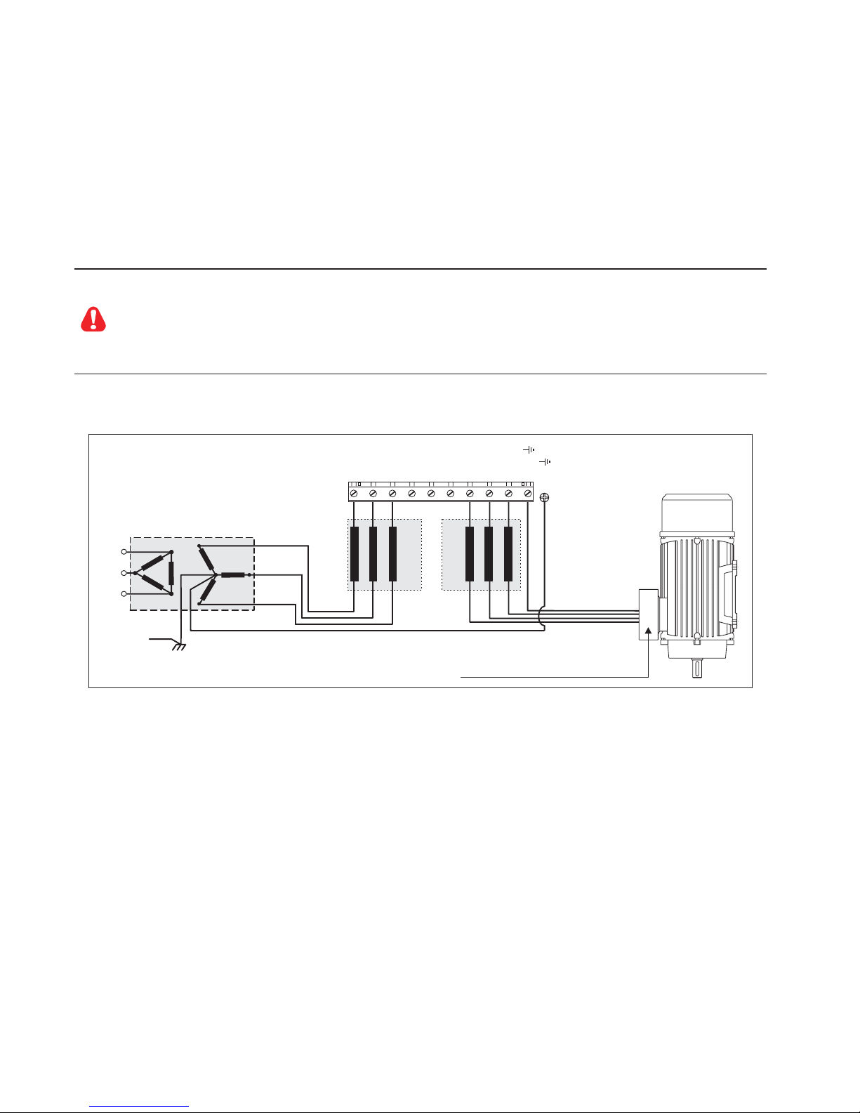
1.1 Power Supply and Grounding
1) SIEI drives are designedto be powered from standardthree phase lines thatare electrically symmetrical with
respecttoground(TNorTTnetwork).
Lesvariateurs SIEI sont prévuspour être alimentés par unréseau triphasé équilibré avecun régime de neutre
standard(TNou TT).
2) In case of supply with IT network, the use of delta/wye transformer is mandatory, with a secondary three phase
wiringreferred to ground.
Si le régime de neutre est IT, nous vous recommendons d'utiliser un tranformateur triangle/étoile avec point milieu
ramenéàla terre.
In case of a three phase supply not symmetrical to ground, an insulation loss of one of the devices
connected to the same network can cause functional problem to the drive, if the use of a delta/wye
transformeris avoided.
Si le réseau n'est pas équilibré par rapport à la terre et qu'il n'y a pas de transformateur raingle/étoile,
une mauvaise isolation d'un appareil électrique connecté au même réseau que le variateur peut lui
causer des troubles de fonctionnement.
Please refer to the following connection sample.
Safety
ground
L1
L2
L3
Earth
U1/L1
V1/L2
W1/L3
U2/T1
V2/T2
W2/T3
PE2/
All wires (including motor ground) must
be connected inside the motor terminal box
AC OUTPUT
CHOKE
AC Main Supply
AC INPUT
CHOKE
PE1/
Warning!

ARTDriveG Instruction manual Chapter 2 - General • 11
Chapter 2 - General
ARTDriveG(AGy) isanAC DigitalInverters forthevariation of the speed ofthree-phasemotors.TheAGy canbesupplied
with a power range from 0.75Kw up to 132Kw (230V...480V) and from 2Hp up to 75Hp (575V).
Anintermediate voltage is generatedfromtherectifiedACvoltage. The Inverter bridgethenproduces,fromthisintermediate
voltage,power supplywithvariable voltageand frequency,by means of sinusoidal evaluated pulse-widthmodulation.This
power supply provides motors with excellent running characteristics, even in a lower range.
The power supply voltage of the various cards is obtained through a switching from the intermediate circuit voltage.
The inverter power part is based on IGBTcomponent (Insulated Gate Bipolar Transistor).The output is protected against
short-circuits and earth faults. It is possible to switch motors on and off during the Inverter operation (see chapter 5.2.3)
If AC motors that are not specially manufactured to operate with an inverter are used, a reduction of 5...10% in supplied
current must be taken into account. In case that the rated torque is requested even in the low frequency range, further
reductions of the heat will be obtained by an external fan. If no assisted ventilation is available, oversizing of the power of
the motor will be necessary. In both cases we suggest to consult the motor manufacturer.
For mechanical reasons (bearings, unbalanced mass, etc.) the motor manufacturer should be consulted when the motor
is operated above the rated frequency.
AGy Inverters can be controlled in different ways:
- via terminal strip on the drive
- via an operator keypad
- via a standard PC program through RS 485 interface
ARTDriveG allows a smooth open-loop control and by using QUIX-ENC option closed-loop control. With closed-loop
control, an encoder (a pulse generator) provides speed feedback information.
Thepowersection and the control electronicsare galvanically isolated.

12 • Chapter 2 - General ARTDriveG Instruction manual
Features
- Supplyvoltagesgenerated by switching starting fromtheintermediate circuit voltage.
- Reduction of motor noise is achieved by the use of a special PWM control procedure.
- Theoutput of the Inverteris protected against shortcircuits and earth faults.
- Motorscan be switched onand off at theInverter output (see chapter5.2.4 of the manual).
- TheInverter isprotectedagainstovercurrents,undervoltages andovervoltages.
- Voltagedips(upto15msfor the power section) can bebridged;forthecontrolsection (see chapter 7.6 for theautomatic
restartprogrammation).
- Sinusoidaloutputcurrentgeneratedbymeansof sinusoidally evaluated pulse-width modulation
- Excellentmotorrunning characteristics, even in the lowerfrequencyrange.
- Programmableslip compensation reduces load-initiated changesinspeed to a minimum.
- Voltagecanbe boosted in the lowerfrequency range, either manuallyor automatically (boost).
- Automaticvoltageandfrequencyadjustmentunderanoverloadensuresthe Inverter cannot stall.
- Parameters can be set either via a keypad or via an RS 485 interface.
- Reference value in the form of an analog signal 0...10 V, -10...10V, 0...20 mA, 4...20 mAas a frequency or via a serial
interface.
- Ramp function generator with linear or S-shaped ramp.
- Direct current braking by commands:
a - thru digital input;
b - automatic injection below a set frequency;
c - Before starting the motor; used with pump and fan drives which are driven by the medium or by the air and are
already turning before the drive is started. D.C. braking prevents the Inverter being switched on when already
turning.
- A range of voltage-frequency characteristics can be selected.
- Overload control.
- Thelast alarm 4 messages canbe stored.Alarm messages areretainedeven afterpower failure.
- Open-looporclosed-loopoperation,asdesired.
- Indication via a potential-free contact and via the interface when a preselected speed is exceeded. Example of an
application: indication of stationary drive.
- Control via an RS 485 serial interface.
- Internal brake unit.
Accessories/Options
- Driveversion (“-C”) withCANopen/DeviceNet integrated.
- External EMC input filters.
- External Input / Output chokes.
- Externalbrakingresistors (connected between terminals Cand BR1).
- Encoderexpansion card: QUIX-ENC (codeS6F36)
- Remote keypad kit (code S5WW5).
-E
2PROM key: PRG-KEY (code S6F38).
- I/Oexpansioncard:EXP-D6A1R1-AGy (code S524L).
- 120Vacdigital input interface card:EXP-D8-120 (code S520L).
- Profibusinterfacecard:SBI-PDP-AGy(codeS5H28).

ARTDriveG Instruction manual Chapter 3 Inspection Procedure, Component Identification and Standard Specification • 13
Chapter 3 - Inspection Procedure, Component Identification
and Standard Specification
3.1 Upon Delivery Inspection Procedures
3.1.1General
Ahigh degree of care is taken in packing theAGy Drives and preparing them for delivery. They should only be transported
with suitable transport equipment (see weight data). Observe the instructions printed on the packaging. This also applies
when the device is unpacked and installed in the control cabinet.
Upon delivery, check the following:
- the packaging for any external damage
- whether the delivery note matches your order.
Open the packaging with suitable tools. Check whether:
- any parts were damaged during transport
- the device type corresponds to your order
Intheeventofanydamageorofanincompleteorincorrectdeliverypleasenotifytheresponsiblesalesoffices immediately.
The devices should only be stored in dry rooms within the specified temperature ranges .
NOTE!A certain degree of moisture condensation is permissible if this arises from changes in temperature (see
section 3.4.1, “Permissible Environmental Conditions”).This does not, however, apply when the devices
are in operation. Always ensure that there is no moisture condensation in devices that are connected to
the power supply!
3.1.2 Inverter Type Designation
The technical specification of the AGy Drive is stated in the type code. Example:
AGy 2 040-KB X-X -X
AGy Drive series
Drive mechanical dimension
Drive kW rating or Hp (for 575V series)
K=keypad included
X=Software standard
B=Integrated braking unit; X= NOT Integrated braking unit
Mains Supply Type
[Blank]=NOT integrated CANopen/DeviceNet
The AGy Drive selected depends on the rated current of the motor. The rated output current at the appropriate service
conditions must be greater than or equal to the motor current required.
Thespeed of the three-phasemotor is determined bythe number of polepairs and the frequency(nameplate, data sheet)
of the motor concerned. Operation above the rated frequency and speed of the motor must take into account the
specificationsgivenbythe manufacturer losses (bearings, unbalance etc.).Thisalsoapplies to temperature specifications
for continuous operation under 20 Hz (poor motor ventilation, not applicable to motors with external ventilation).
14 • Chapter 3 IInspection Procedure, Component Identification and Standard Specification ARTDriveG Instruction manual
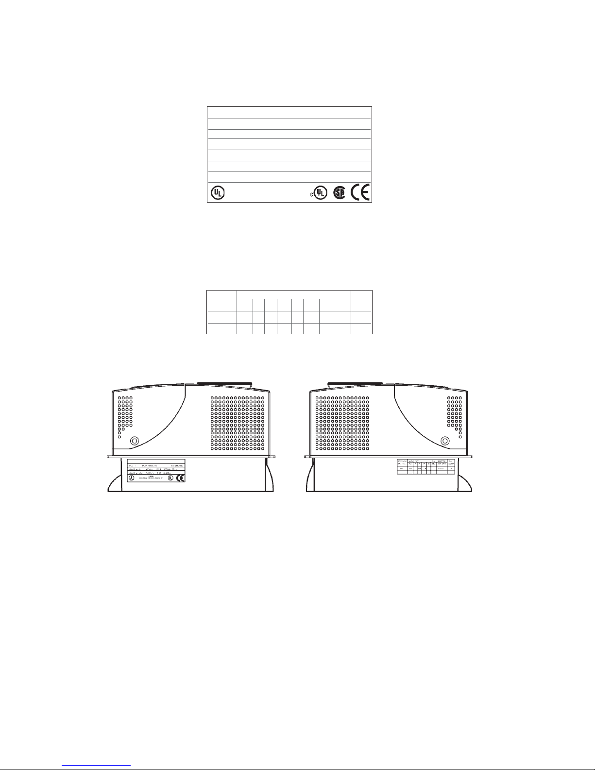
3.1.3Nameplate
Check that all the data stated in the nameplate enclosed to the inverter correspond to what has been ordered.
Figure3.1.3.1:Identification Nameplate (example for 575V series)
Type : AGy 2003 -KBX-5 Inverter Drive S/N 02135387
Inp: 575 Vac 50/60Hz 3Ph Zmin=1%
4.5A@575Vac With Line Choke
Out : 0-575Vac 400Hz 3Ph 3Hp @ 575Vac
4.1A@575V Ovld. 150% 60s
LISTED
INDUSTRIAL CONTROL EQUIPMENT
SIEI SPA
®
Type: Inverter model
S/N: Serial number
Main Power In: Power supply voltage - AC Input current - Frequency
Main Power Out: Output voltage - Output current - Output frequency
Figure3.1.3.2:Firmware&CardRevision Level Nameplate
Firmware HW release S/N 0162330 Prod.
R elease D F P R S BU SW . CFG CONF
C 2.03 A -.A -.- 1.000 A1
Figure 3.1.3.3: Nameplates Position
ARTDriveG Instruction manual Chapter 3 Inspection Procedure, Component Identification and Standard Specification • 15
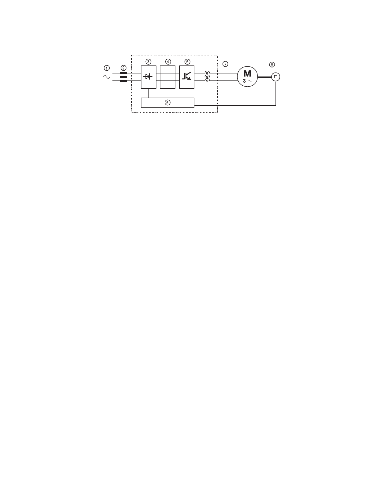
3.2 Component Identification
Figure 3.2.1: Basic Setup of Frequency Inverter
An AGy Drive converts the constant voltage and frequency of a three-phase power supply into a direct voltage and then
converts this direct voltage into a new three-phase power supply with a variable voltage and frequency. This variable
three-phase power supply can be used for the infinitely variable adjustment of the speed of three-phase asynchronous
motors.
1 AC Input supply voltage: 230V ... 480V for “AGy...-4 and 575V for “AGy...-5”.
2 AC Mains choke (see section 5.7.1).
3 Three-phase rectifier bridge
Converts the alternating current into direct current using a three phase full wave bridge.
4 DC intermediate circuit
With charging resistor and smoothing capacitor.
Direct voltage (UDC) = √2 x Mains voltage (ULN)
5 IGBT inverter
Converts direct voltage to a variable three-phase alternating voltage with variable frequency.
6 Configurable control section
Modules for open-loop and closed-loop control of the power section. This is used for processing control commands,
reference values and actual values.
7 Outputvoltage:
Three-phase, variable alternating voltage from 0 up to 94% of Mains voltage (ULN).
8 Encoder(option)
For speed feedback (see section 4.4.2).

16 • Chapter 3 IInspection Procedure, Component Identification and Standard Specification ARTDriveG Instruction manual
3.3 Standard Specifications
3.3.1PermissibleEnvironmentalConditions
Table 3.3.1.1: Environmental Specification
[°C] 0 … +40; +40…+50 with derating
[°F] 32 … +104; +104…+122 with derating
Installation location
Installation altitude
Temperature:
operation
1)
operation
2)
storage
transport
Air humidity:
operation
storage
transport
Air pressure:
operation [kPa] 86 to 106 (class 3K3 as per EN50178)
storage [kPa] 86 to 106 (class 1K4 as per EN50178)
transport [kPa] 70 to 106 (class 2K3 as per EN50178)
General standards
Safety
Climatic conditions
Clearance and creepage
Vibration
EMC compatibility
Rated input voltages
Approvals
TGy0020
-20…+60°C (-4…+140°F), for devices with keypad
IP20 according to EN 60529
IP54 for the cabinet with externally mounted heatsink; only for sizes from 1007 to 3150 (230V…480V) and
from 2002 to 3020 (575V)
EN 50178, UL508C, UL840. Overvoltage category for mains connected circuits: III; degree of pollution 2
EN 60068-2-6, test Fc.
-20…+55°C (-4…+131°F), for devices with keypad
CE, UL, cUL, CSA
ENVIRONMENT
STANDARD
Pollution degree 2 or better (free from direct sunligth, vibration, dust, corrosive or inflammable gases, fog,
vapour oil and dripped water, avoid saline environment)
Up to 1000m (3281 feet) above sea level; for higher altitudes a current reduction of 1.2% for every 100m (328
feet) of additional height applies .
A light condensation of moisture may occur for a short time occasionally if the device is not in operation (class 2K3 as per
EN50178)
EN61800-3 (see “EMC Guidelines” instruction book)
IEC 60038
-25…+70°C (-13…+158°F), class 2K3 per EN50178
T
A
Ambient temperature
0…40°C (32°…104°F)
0…50°C (32°…122°F)
-25…+55°C (-13…+131°F), class 1K4 per EN50178
Protection degree
95 %
3)
60 g/m
4)
EN 61800-1, IEC 143-1-1.
5 % to 85 %, 1 g/m
3
to 25 g/m
3
without moisture condensation or icing (Class 3K3 as per EN50178)
5% to 95 %, 1 g/m
3
to 29 g/m
3
(Class 1K3 as per EN50178)
EN 50178, UL 508C
EN 60721-3-3, class 3K3. EN 60068-2-2, test Bd.
1) Over40°C(104°F):
- current reduction of 2% of rated output current per K
-remove front plate (betterthan class 3K3 as perEN50178)
2) Currentderatedto0.8 rated ouput current
Over40°C(104°F): removalof the top cover (better thanclass3K3as per EN50178)
3) Greatestrelativeairhumidityoccurswiththetemperature@40°C (104°F) or if the temperature of the device is brought
suddenlyfrom-25...+30°C(-13°...+86°F).
4) Greatestabsoluteair humidity if the deviceis brought suddenly from 70...15°C(158°...59°F).

ARTDriveG Instruction manual Chapter 3 Inspection Procedure, Component Identification and Standard Specification • 17
Disposal of the Device
The AGy Drive can be disposed as electronic scraps in accordance with the currently valid national regulations for the
disposal of electronic parts.
The plastic covering of the Drives are recyclable: the material used is >ABS+PC< .
3.3.2 Mains Connection and Inverter Output
The AGy Drive must be connected to an AC mains supply capable of delivering a symmetrical short circuit current lower
or equal to the values indicated on table 3.3.2.1. For the use of an AC input choke see paragraph 5.7.1.
Note from the table of paragraph 3.3.2.1. the allowable mains voltages. The cycle direction of the phases is free.
Voltages lower than the min. tolerance values can cause the block of the inverter.
Itis possible toobtainthe automatical restart of theinverter, afteranother failure has occured (For further information, see
paragraph7.6,Autoreset Configurationsection).
NOTE!In some cases AC Input chokes, and possibly noise suppression filters should be fitted on the AC
Input side of the device. See chapter “Chokes/Filters”.
AdjustableFrequencyDrivesandAC Input filters have ground discharge currents greater than 3.5mA.EN50178specifies
that with discharge currents greater than 3.5 mA the protective conductor ground connection (PE1) must be fixed type.

18 • Chapter 3 IInspection Procedure, Component Identification and Standard Specification ARTDriveG Instruction manual
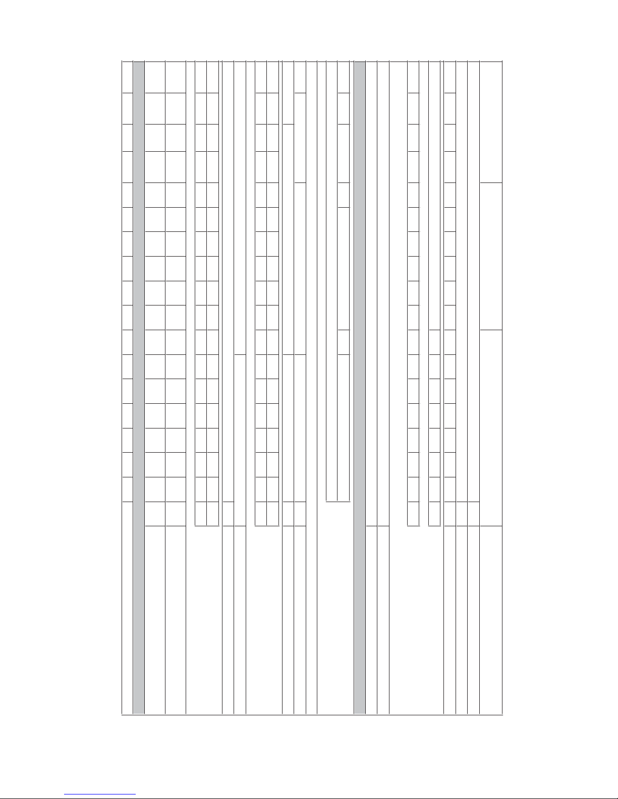
Table 3.3.2.1-A: AC Input/Output Specifications for 230V...480V Drive Kw/Hp Rating
1007 1015 1022 1030 2040 2055 2075 3110 3150 4220 4300 4370 5450 5550 6750 7900 71100 71320
Inverter Output (IEC 146 class1), Continuous service
(@ 400Vac)
[kVA] 1.6 2.7 3.8 5 6.5 8.5 12 16.8 22.4 32 42 55 64 79 98 128 145 173
Inverter Output (IEC 146 class2),150% overload for
60s (@ 400Vac)
[kVA] 1.4 2.4 3.4 4.5 5.9 7.7 10.9 15.3 20.3 29 38.2 50 58.3 72 89.2 116.5 132 157.5
PNmot (recommended motor output):
@U
LN=230Vac; fSW=default; IEC 146 class 1
[kW] 0.37 0.75 1.1 1.5 2.2 3 4 5.5 7.5 11 18.5 22 22 30 37 55 55 75
@U
LN=230Vac; fSW=default; IEC 146 class 2
[kW] 0.37 0.75 1.1 1.5 2.2 3 4 5.5 7.5 11 15 18.5 22 30 37 45 55 55
@U
LN=230Vac; fSW=default; IEC 146 class 1
[Hp] 0.50 1 1.5 2 3 4 5 7.5 10 15 25 30 30 40 50 75 75 100
@U
LN=230Vac; fSW=default; IEC 146 class 2
[Hp] 0.50 1 1.5 2 3 4 5 7.5 10 15 20 25 30 40 50 60 75 75
@U
LN=400Vac; fSW=default; IEC 146 class 1
[kW] 0.75 1.5 2.2 3 4 5.5 7.5 11 15 22 30 37 45 55 75 90 110 132
@U
LN=400Vac; fSW=default; IEC 146 class 2
[kW] 0.75 1.5 2.2 3 4 5.5 7.5 11 15 22 30 37 45 55 55 90 90 110
@U
LN=460Vac; fSW=default; IEC 146 class 1
[Hp] 123357.51015203040506075100125150150
@U
LN=460Vac; fSW=default; IEC 146 class 2
[Hp] 0.75 1.5 2 3 5 7.5 10 15 20 25 30 40 50 60 75 100 125 150
U2Max output voltage
[V]
f2Max output frequency
[Hz]
I2N Rated output current :
@U
LN=230-400Vac; fSW= default; IEC 146 class 1
[A] 2.4 4 5.6 7.5 9.6 12.6 17.7 24.8 33 47 63 79 93 114 142 185 210 250
@U
LN=230-400Vac; fSW=default; IEC 146 class 2
[A] 2.2 3.6 5.1 6.8 8.7 11.5 16.1 22.5 30 43 58 72 85 104 129 169 191 227
@U
LN=460Vac; fSW=default; IEC 146 class 1
[A] 2.1 3.5 4.9 6.5 8.3 11 15.4 21.6 28.7 40 54 68 81 99 124 160 183 217
@U
LN=460Vac; fSW=default; IEC 146 class 2
[A] 1.9 3.2 4.4 5.9 7.6 10 14 19.6 26 36 50 62 74 90 112 146 166 198
fSW switching frequency (Default)
[kHz]
fSW switching frequency (Higher)
[kHz]
Derating factor:
Voltage Factor KVat 460 Vac **
0.87 0.87 0.87 0.86 0.86 0.87 0.87 0.87 0.78 0.76 0.79 0.78 0.79 0.79 0.78 0.78 0.78 0.78
Temp. Factor K Tfor ambient temperature
Switching frequency KF
ULN AC Input voltage
[V]
AC Input frequency
[Hz]
INAC Input current for continuous service :
- Connection with 3-phase reactor
@ 230Vac; IEC 146 class1
[A] 1.7 2.9 4 5.5 * 7 9.5 14 * 18.2 25 * 39 55 69 84 98 122 158 192 220
@ 400Vac; IEC 146 class1
[A] 1.9 3.3 4.5 6.2 * 7.9 10.7 15.8 * 20.4 28.2 * 44 62 77 94 110 137 177 216 247
@ 460Vac; IEC 146 class1
[A] 1.7 2.9 3.9 5.4 * 7 9.3 13.8 * 17.8 24.5 * 37 53 66 82 96 120 153 188 214
- Connection without 3-phase reactor
@ 230Vac; IEC 146 class1
[A] 3.6 4.4 6.8 7.9 * 11 15.5 21.5 * 27.9 35.4 *
@ 400Vac; IEC 146 class1
[A] 3.9 4.8 7.4 9 * 12 16.9 24.2 * 30.3 40 *
@ 460Vac; IEC 146 class1
[A] 3.4 4.2 6.4 7.8 * 10.4 14.7 21 * 26.4 34.8 *
Max short circuit power without line reactor (Zmin=1%) [kVA] 160 270 380 500 650 850 1200 1700 2250 3200 4200 5500 6400 7900 9800 12800 14500 17300
Overvoltage threshold
[V]
Undervoltage threshold
[V]
Braking IGBT Unit
Standard internal (with external resistor);
MAX Braking torque :
TGy0031
For these types an external inductance is recommended
0.8 @ 50°C (122°F)
300500
8
8
4
16
150% 70%
410VDC (for 230VAC mains), 800VDC (for 400VAC mains), 800VDC (for 460VAC mains)
230VDC (for 230VAC mains), 380VDC (for 400VAC mains), 415VDC (for 460VAC mains)
150% 120%
AGy Drive Type - Kw rating
OUTPUT
90% Option internal (with external
resistor); Braking torque 150% External braking unit (optional)
INPUT
0.94 x ULN (AC Input voltage)
0.7 for higher f
sw
50/60 Hz ±5%
230 V -15% … 480 V +10%, 3Ph
*: For the specified power sizes, the external reactor is strongly recommended
**: Linear shapes for KV, KT, respectively in the ranges [400, 460] Vac, [40, 50]°C, (104, 122)°F.
Example: for AC mains = 440VAC, 400V/440V = 0.90 = KV
ARTDriveG Instruction manual Chapter 3 Inspection Procedure, Component Identification and Standard Specification • 19
Table 3.3.2.1-B: AC Input/Output Specifications for 575VDrive Hp Rating
AGy Drive Type - Hp rating 2002 2003 2005 3007 3010 3015 3020 4025 4030 4040 5050 5060 5075 6100 7125 7150 8200
Inverter Output (IEC 146 class1), Continuous service
[kVA]
3.8 4.5 7.0 10.8 13.7 18.6 24.1 30 36 46 58 69 86 109 136 157 210
Inverter Output (IEC 146 class2), 150% overload for
60s
[kVA]
3.4 4.1 6.3 9.8 12.5 16.9 21.9 27 33 42 53 63 78 99 124 143 191
PNmot (recommended motor output):
@U
LN=575Vac; fSW=default; IEC 146 class 1
[Hp]
2 3 5 7.5 10 15 20 25 30 40 50 60 75 100 125 150 200
@U
LN=575Vac; fSW=default; IEC 146 class 2
[Hp]
2 3 5 7.5 10 15 20 25 30 40 50 60 75 100 125 150 200
U2Max output voltage
[V]
f2Max output frequency (*)
[Hz]
I2N Rated output current :
@U
LN=575Vac; fSW= default; IEC 146 class 1
[A]
3.8 4.5 7.0 10.8 13.8 18.7 24.2 30 36 46 58 69 86 109 137 158 211
@U
LN=575Vac; fSW=default; IEC 146 class 2
[A]
3.5 4.1 6.4 9.8 12.6 17.0 22.0 27 33 42 53 63 78 99 125 144 192
fSW switching frequency (Default)
[kHz]
fSW switching frequency (Higher)
[kHz]
2
Derating factor:
KTfor ambient temperature
KFfor switching frequency 0.87 0.64 0.87 t.b.d.
ULN AC Input voltage
[V]
AC Input frequency
[Hz]
INAC Input current for continuous service :
- Connection with 3-phase reactor
@ 575Vac; IEC 146 class1
[A]
3.8 4.7 7.4 11.7 15 19.8 25.9 31 35 46 60 68 85 114 146 163 220
- Connection without 3-phase reactor
@ 575Vac; IEC 146 class1
[A]
5.3 6.1 9.9 17 20.7 27.6 33.9
Max short circuit power without line reactor (Zmin=1%)
[kVA]
380 450 700 1080 1370 1860 2410 3000 3600 4600 5800 6900 8600 10900 13700 15700 21000
Overvoltage threshold
[V]
Undervoltage threshold
[V]
Braking IGBT Unit (standard drive)
TGy0030
DC choke integrated
0.94 x ULN (AC Input voltage)
8
200
16
8
1000 VDC
565 VDC (for 575 VAC mains)
External braking unit (optional)
Optional internal braking unit (with external
resistor); braking torque 150%
Standard internal (with external resistor); Braking torque
150%
INPUT
0.7 for higher f
SW
400
42
4
t.b.d.
0.8 for higher f
SW
OUTPUT
0.8 @ 50°C (122°F)
500 -10% / 575V ±10%, 3Ph
50/60 Hz ±5%

20 • Chapter 3 IInspection Procedure, Component Identification and Standard Specification ARTDriveG Instruction manual
3.3.3ACInput Current
NOTE!The Input current of the Drive depends on the operating state of the connected motor. The tables
3.3.2.1 shows the values corresponding to rated continuous service, keeping into account typical
output power factor for each size
3.3.4 AC Output
The output of the AGy Drive is ground fault and phase to phase output short protected.
NOTE!Theconnectionofan external voltagetotheoutput terminals oftheDriveisnot permissible!Itisallowed to
disconnect the motor from the Drive output, after the Drive has been disabled.
Therated value of directcurrent output ( ICONT ) dependson the supply voltage( KV), the ambient temperature( KT) and the
switching frequency (KF) if higher than the default setting:
ICONT = I2N x KVx KT(Values of derating factor are the listed on tables 3.3.2.1) with an overload capacity IMAX = 1.5 x ICONT
for 60 seconds.
Recommended motor outputs
The coordination of the motor rated powers with the Drive type presented in the table 3.3.2.1 refers to the use of standard
motors with a rated voltage equal to the rated voltage of the input supply.
As for those motors with different voltages, the type of Drive to use is determined by the rated current of the motor.
NOTE!Max allowed overload:
136% . I2N cl.1 ≡150% . I2N cl.2
Table 3.3.4.1 shows nominal current values for typical service profiles (Ambient temperature =40°C
[104°F],standardswitchingfrequency).
Similarcriteriaapply for operation with additional deratingfactors.
Table 3.3.4.1: Nominal Drive Current
I2N (1) I2N (2) I2N (3) I2N (4) I2N (5) I2N (6)
[A] [A] [A] [A] [A] [A]
1007 2.4 2.2 2.1 1.9 2002 3.8 3.4
1015 4 3.6 3.5 3.2 2003 4.5 4.1
1022 5.6 5.1 4.9 4.4 2005 7.0 6.3
1030 7.5 6.8 6.5 5.9 3007 10.8 9.8
2040 9.6 8.7 8.3 7.6 3010 13.7 12.5
2055 12.6 11.5 11 10 3015 18.6 16.9
2075 17.7 16.1 15.4 14 3020 24.1 21.9
3110 24.8 22.5 21.6 19.5 4025 30 27
3150 33 29.9 25.7 23 4030 36 33
4220 47 42.6 35.7 32.3 4040 46 42
4300 63 57.1 49.7 45 5050 58 53
4370 79 71.6 61.6 55.8 5060 69 63
5450 93 84.3 73 66.6 5075 86 78
5550 114 103.4 89 80.6 6100 109 99
6750 142 129 110.7 100 7125 136 124
7900 185 169 144 132 7150 157 143
71100 210 191 163.8 149 8200 210 191
71320 250 227 195 177
TGy0040
AGy…-4 (230V…480V)
Drive
Type
Drive
Type
AGy…-5 (575V)
(1): I2N Rated output current (@ ULN=230-400Vac),
Continuous service, no overload (IEC 146 class 1)
(2): I2N Rated output current (@ ULN=230-400Vac), Overload
service150%x60s followed by IN,min.cycletime360s(IEC
146 class 2).
(3): I2N x kV Rated output current (@ ULN=460-480Vac),
Continuous service, no overload (IEC 146 class 1)
(4): I2N x kV Rated output current (@ ULN=460-480Vac),
Overload service 150%x60s followed by IN, min.cycle time
360s (IEC 146 class 2).
(5) I2N Rated output current (@ ULN=575Vac), continuous
service, no overload (IEC 146 classe 1).
(6) I2N Rated output current (@ ULN=575Vac), overload
service 150%x60s followed by IN, min. cycle time 360s
(IEC 146 classe 2).
Table of contents
Other Siei Inverter manuals

Popular Inverter manuals by other brands


Olimpia splendid
Olimpia splendid DC 18 HP Instructions for installation, use and maintenance

Thermal Arc
Thermal Arc FABRICATOR 181i Service manual

Tsun
Tsun TITAN TSOL-MP3000 Quick installation guide

GE
GE HOME NERATOR 7000 WATT Installation and start-up manual

Advanced Energy
Advanced Energy AE 600 user manual

Victron energy
Victron energy RS Smart manual


