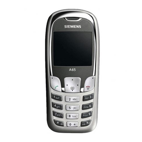
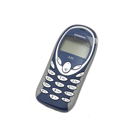
Siemens A55 Operator's manual

V 1.10 Page 1of 45 ICM MP CCQ GRM
A52/A55/C55 IFX Company Confidential © Copyright Siemens AG 08/03
A52, A55 & C55 IFX
Level 2.5e
Repair Documentation
V 1.10
Version Date Department Notes to change
V 1.00 09.052003 ICM MP CCQ GRM New document
V 1.10 11.08.2003 ICM MP CCQ GRM Document modified (A52)

V 1.10 Page 2of 45 ICM MP CCQ GRM
A52/A55/C55 IFX Company Confidential © Copyright Siemens AG 08/03
Table of Contents:
1LIST OF AVAILABLE LEVEL 2,5E PARTS C55 IFX ......................................... 4
2REQUIRED EQUIPMENT FOR LEVEL 2,5E ...................................................... 5
3REQUIRED SOFTWARE FOR LEVEL 2,5E C55 IFX......................................... 5
4RADIO PART DESCRIPTION............................................................................. 6
4.1 Introduction..................................................................................................... 6
4.2 Power Supply RF-Part .................................................................................... 7
4.3 Frequency generation .................................................................................... 7
4.3.1 Synthesizer: The discrete VCXO (26MHz)...........................................................................7
4.3.2 Synthesizer: LO1..................................................................................................................8
4.4 Antenna Switch / External Antenna Connector (electrical/mechanical only
C55) 10
4.5 Frontendmodul (Electrical Antenna Switch) .............................................. 10
4.6 Receiver......................................................................................................... 11
4.6.1 Receiver: EGSM900/GSM1800 – Filter to Demodulator ...................................................11
4.6.2 IC Overview ........................................................................................................................13
4.7 Transmitter.................................................................................................... 15
4.7.1 Transmitter: Modulator and Limited Amplifier ....................................................................15
4.7.2 Transmitter: and Power Amplifier.......................................................................................16
5LOGIC / CONTROL........................................................................................... 17
5.1 Overview of Hardware Structure ................................................................. 17
5.1.1 Logic Block Diagram ..........................................................................................................17
5.1.2 Block Diagram C55 IFX Control Part .................................................................................17
5.1.3 EGOLD+.............................................................................................................................18
5.1.4 SRAM .................................................................................................................................22
5.1.5 FLASH ................................................................................................................................22
5.1.6 SIM .....................................................................................................................................22
5.1.7 Vibration Motor ...................................................................................................................23
6POWER SUPPLY.............................................................................................. 23
6.1 Power Supply ASIC ...................................................................................... 23
6.1.1 Power Supply Operating modes: .......................................................................................25
6.1.2 Power Supply Functions:....................................................................................................26
6.2 Battery ........................................................................................................... 33
6.3 Charging Concept......................................................................................... 34
V 1.10 Page 3of 45 ICM MP CCQ GRM
A52/A55/C55 IFX Company Confidential © Copyright Siemens AG 08/03
7INTERFACES.................................................................................................... 37
7.1 Vibra............................................................................................................... 37
7.2 Earpiece......................................................................................................... 37
7.3 Microphone ................................................................................................... 38
7.4 Battery ........................................................................................................... 38
7.5 IO Connector with ESD protection.............................................................. 39
7.5.1 IO Connector – New Slim Lumberg ...................................................................................39
7.5.2 ESD Protection with EMI filter ............................................................................................40
7.6 SIM ................................................................................................................. 41
7.7 Display........................................................................................................... 41
8ACOUSTIC........................................................................................................ 42
8.1 Microphone ................................................................................................... 42
8.1.1 Mechanical .........................................................................................................................42
8.1.2 Electrical .............................................................................................................................42
8.2 Earpiece/Loudspeaker ................................................................................. 43
8.2.1 Mechanical .........................................................................................................................43
8.2.2 Electrical .............................................................................................................................43
9DISPLAY AND ILLUMINATION........................................................................ 44
9.1 Display........................................................................................................... 44
9.2 Illumination ................................................................................................... 44
10 KEYBOARD ................................................................................................... 45

V 1.10 Page 4of 45 ICM MP CCQ GRM
A52/A55/C55 IFX Company Confidential © Copyright Siemens AG 08/03
1 List of available level 2,5e parts C55 IFX
ID-No Type Board Name, Location Part-No.
D150 VCO HIT Transmitter_VCO L36820-L6097-D670
D1600 VCO IFX Transmitter_VCO L36820-L6109-D670
D171 IC HIT/IFX Egold+ L36810-G6149-D670
D1740 Filter IFX Ant_Switch_Diplexer L36197-F5006-F936
D1785 IC IFX Transceiver IC L36197-F5011-F334
D361 IC HIT/IFX ASIC L36145-J4682-Y43
D800 IC HIT Transceiver IC L36820-L6105-D670
D920 IC HIT PA_Comperator L36820-L6133-D670
R1507 Resistor IFX Temp_Resistor L36120-F4223-H
R959 Resistor HIT Temp_Resistor L36120-F4223-H
V1500 Diode IFX Capa_Diode L36840-D61-D670
V151 Diode HIT/IFX Diode_KB7 L36840-D5062-D670
V181 Diode HIT/IFX Diode_Battery_Interface L36702-A1051
V211 Transistor HIT/IFX Tran._Vibra L36830-C1097-D670
V220 Diode HIT/IFX Diode_Vibra L36851-Z9105-Z981
V222 Transistor HIT/IFX Trans_Light_ L36830-C1112-D670
V223 Transistor HIT Trans_Light_ L36840-C4004-D670
V361 Transistor HIT/IFX Tran._Charge L36830-C1110-D670
V850 Transistor HIT Tran._VCO_Switch L36820-C6047-D670
V920 Diode HIT Feedback_Diode L36840-D5049-D670
V921 Transistor HIT Tran._PA_Switch L36820-C6047-D670
V950 Transistor HIT Tran._26MHz_Ampl. L36840-C4049-D670
V951 Diode HIT Capa_Diode L36840-D61-D670
Z1500 Quartz IFX Oszillator_26MHz L36145-F260-Y17
Z1600 Filter IFX Transmitter_Filter L36145-K280-Y242
Z1700 IC IFX Power_Amplifier L36197-F5005-F487
Z171 Quartz HIT/IFX Quarz/Egold L36145-F102-Y8
Z211 Filter HIT/IFX Logic/IO_Interface L36197-F5000-F116
Z850 VCO HIT 1LO_VCO L36145-G100-Y96
Z851 Filter HIT Filter_BALUN L36145-K260-Y41
Z880 IC HIT Ant_Switch_Diplexer L36145-K280-Y257
Z900 IC HIT Power_Amplifier L36851-Z2002-A59
Z950 Quartz HIT Oszillator_26MHz L36145-F260-Y17

V 1.10 Page 5of 45 ICM MP CCQ GRM
A52/A55/C55 IFX Company Confidential © Copyright Siemens AG 08/03
2 Required Equipment for Level 2,5e
- GSM-Tester (CMU200 or 4400S incl. Options)
- PC-incl. Monitor, Keyboard and Mouse
- Bootadapter 2000/2002 (L36880-N9241-A200)
- Adapter cable for Bootadapter due to new Lumberg connector
- Troubleshooting Frame C55 (F30032-P209-A1)
- Power Supply
- Spectrum Analyser
- Active RF-Probe incl. Power Supply
- Oscilloscope incl. Probe
- RF-Connector (N<>SMA(f))
- Power Supply Cables
- Dongle (F30032-P28-A1) if USB-Dongle is used a special driver for NT is required
- BGA Soldering equipment
Reference: Equipment recommendation V1.2
(downloadable from the technical support page)
3 Required Software for Level 2,5e C55 IFX
- Windows NT Version4
- Winsui version1.43 or higher
- Software for GSM-Tester ( Cats(Acterna/Wiltek) or CMU-GO(Rohde&Schwarz) )
- Software for reference oscillator adjustment
- Internet unblocking solution
- Dongle driver for USB-Dongle if used with WIN NT4

V 1.10 Page 6of 45 ICM MP CCQ GRM
A52/A55/C55 IFX Company Confidential © Copyright Siemens AG 08/03
4 Radio Part Description
4.1 Introduction
The radio part is necessary to convert the GMSK-RF-signals from the antenna to the
baseband and vice versa.
In the receiving direction, the signals are split in the I- and Q-component and fed to the
A/D-converter of the logic part. In the transmission direction, the GMSK-signal is
generated with the Direct Modulator by modulation of the I- and Q-signals, which are
generated in the baseband section. After the modulation the RF-signals are amplified by
a buffer-limiter and, for the GSM900 path, filtered with a SAW-Filter. Finally, the power
amplifier (PA) is attached to reach the output power.
Transmitter and Receiver are never active at the same time. Simultaneous
reception in the EGSM 900 and GSM 1800 band is impossible as well as
simultaneous transmission in both bands. However the monitoring band
(monitoring timeslot) in the TDMA-frame can be chosen independently of the
receiving or transmitting band (RX- and TX timeslot of the band).
The RF-part is designed for dualband operation (EGSM 900, GSM 1800) and consists of
the following main components:
1. 26MHz reference crystal Z1500
2. TX-Filter in GSM section Z1600
3. Transmitter power amplifier RF9340 with integrated regulator Z1700
4. Front-End-Module including RX-/TX-switch and EGSM 900/GSM1800 receiver SAW-
filters D1740
5. Infineon Limiter/Buffer PMB2256 to amplify the RF signals from the modulator to
drive the PA D1600
6. Infineon Smarti DC2 PMB6256 with the following functionality D1785:
• Integrated active part of the 26MHz crystal oscillator
• PLL for local oscillator LO1
• LO1-VCO
• Direct conversion receiver with channel filtering
• Direct Modulator
• Active part of the reference oscillator including buffer
• Control circuit for band switch

V 1.10 Page 7of 45 ICM MP CCQ GRM
A52/A55/C55 IFX Company Confidential © Copyright Siemens AG 08/03
4.2 Power Supply RF-Part
The voltage regulator for the RF-part is located inside the ASIC D361.(see chapter 5.2).It
generates the required 2,85V “RF-Voltages” named VCC2_8 and VCC_SYN.(VCC_SYN
is also named VCC2 and behind R1451 VCC_OSC)
The following components are supplied by:
VCC2_8
• Limiter amplifier
VCC_SYN
• Modulators
• RX mixers
• VCO
• PLL
• 26 MHz reference oscillator
The voltage regulator RFREG 1 is controlled by the signal SLEEPQ (RF_EN (RF REG G2)),
RFREG2 is controlled by he signal VCXOEN_UC connected to SLEEP1_N (on/off Control
H1). Both signals are provided by the EGOLD+ (SLEEPQ (GSM TDMA-Timer H16) /
VCXOEN_UC (Miscellaneous R6)).
Circuit diagram
4.3 Frequency generation
4.3.1 Synthesizer: The discrete VCXO (26MHz)
The reference oscillator is a 26 MHz voltage controlled crystal oscillator. It has two main
tasks:
• It is used as reference for the synthesizer phase/frequency detector (Smarti
internal circuit)
• It gives the clock for the processor (E-Gold)
The main block is realized as an internal transistor cell with a Colpitts structure. The 26
MHz quartz crystal is connected to a tuning circuit that allows a fine-tuning of the
frequency. A current mirror, acting as buffer and amplifier followed by a LC resonant
circuit makes the signal to fit the E-Gold clock signal requirements. ON/OFF signal
(VCC_OSC) comes from the ASIC via the resistor R1451. For temperature
measurements of the VCXO a temperature resistance (R700) is used. The resistor is
placed near the VCXO. The measurement result TVCXO is reported to the EGOLD+
(Analog Interface P3) via R138 as the signal TENV. The frequency of the reference oscillator
can be adjusted by the EGOLD+ via a PNM- modulated AFC-signal.
The signal leaves the SMARTI as BB_SIN26M at pin 4 to be further used from the
EGOLD+ (D171 (functional T3)).
The required voltage VCC_SYN is provided by the ASCI D361
V
CC2
_
8
V
CC
_
SYN

V 1.10 Page 8of 45 ICM MP CCQ GRM
A52/A55/C55 IFX Company Confidential © Copyright Siemens AG 08/03
Circuit diagram
4.3.2 Synthesizer: LO1
The local oscillator (LO1) consists of a PLL inside the Smarti DC (D720), an external loop
filter. The VCO is build in.
The first local oscillator is needed to generate frequencies which enables the transceiver IC
to demodulate the receiver signal and to perform the channel selection in the TX part. The
LO1/PLL part is switched on with PLLON (pin 5) from the EGOLD+ (D171 (GSM TDMA Timer
F16)). The PLL settings are programmed by the 3 wire bus RFCLK (pin 1), RFDATA (pin2)
and RFSTR (pin3). The LO frequency is 4 times the RX/TX frequency for EGSM 900 and 2
times for GSM1800.
This LO1 frequency range
The required voltage VCC_SYN is provided by the ASIC D361
from EGOLD
to EGOLD+

V 1.10 Page 9of 45 ICM MP CCQ GRM
A52/A55/C55 IFX Company Confidential © Copyright Siemens AG 08/03
Block diagram
Circuit diagram
~
~
External
loopfilter
External
loopfilter

V 1.10 Page 10of 45 ICM MP CCQ GRM
A52/A55/C55 IFX Company Confidential © Copyright Siemens AG 08/03
4.4 Antenna Switch / External Antenna Connector
(electrical/mechanical only C55)
The mechanical antenna switch for the differentiation between the internal and external
antenna.
4.5 Frontendmodul (Electrical Antenna Switch)
EGSM900/GSM1800 <> Receiver/Transmitter
The frontend has two functions.
- to select the different GSM bands
- to switch between RX and TX mode
Inside the frontendmodul SAW filters are integrated in the RX paths.
For dual band mode the FEM needs two supply voltages (VC1, VC2) that are directly
provided by the Smarti DC (FEM1 and FEM2). The following logical table shows the
different modes of the FEM.
Mode Selection Vc. 1 Vc.2 Vc.3
EGSM900 RX LOW LOW LOW
EGSM900 TX HIGH LOW LOW
GSM1800 RX LOW LOW LOW
GSM1800 TX LOW HIGH LOW
GSM1900 RX LOW LOW HIGH
GSM1900 TX LOW HIGH LOW
Two balanced SAW filters are integrated to have good stop-band attenuation in the GSM
and the PCN RX paths.
Top View
Block diagram
to / from
di
p
lexe
r
External Internal

V 1.10 Page 11of 45 ICM MP CCQ GRM
A52/A55/C55 IFX Company Confidential © Copyright Siemens AG 08/03
4.6 Receiver
4.6.1 Receiver: EGSM900/GSM1800 – Filter to Demodulator
From the antenna switch, up to the demodulator the received signal passes the following
blocks to get the demodulated baseband signals for the EGOLD+:
Inside Z650 Smarti Smarti Smarti
Filter: The EGSM900, GSM1800 filters are located inside the frontend module. The Filter
are centred to a frequency of 942,5MHz for EGSM900, 1847,5MHz for GSM1800.
LNA: The LNA´s (EGSM900/GSM1800) are located inside the Smarti. The LNA can be
switched in HIGH (On) and LOW (Off) mode and is controlled by the Smarti depending on
EGOLD+ information.
Demodulator: The Smarti DC consists of a direct conversion receiver for GSM 900/1800.
The amplified RF signal is converted by a quadrature demodulator to the final
outputsignals at baseband frequency. The LO signals are generated by a divider by 4 for
the GSM900 band and by a divider by 2 for GSM1800 band.
The resulting in-phase and quadratursignals are fed into two baseband low pass filters and
the PGC amplifier chain. The baseband filter provide a suppression of inband-blocking and
adjacent channel interferers.
PGC: After baseband filtering the signal is fed into a PGC amplifier chain. The baseband
amplifier offers 78 dB programmable gain with 2 dB steps. Due to the high baseband gain
(58 dB), DC offsets can corrupt the signal at the baseband outputs. Differential offset
voltages are reduced by an internal offset compensation circuit. The control is realised
through the EGOLD+ signals (RFDATA; RFCLK; RFSTR.(RF Control J15, J16, J17).
Filter LNA PGC
Demodulator
to Demodulator
to Antenna
from
P
A
Control Signals
from Smarti

V 1.10 Page 12of 45 ICM MP CCQ GRM
A52/A55/C55 IFX Company Confidential © Copyright Siemens AG 08/03
The required voltage VCCSYN is provided by the ASIC D361
Circuit diagram
Top view
to EGOLD+
progr. signals
from
antenna
PMB6256

V 1.10 Page 13of 45 ICM MP CCQ GRM
A52/A55/C55 IFX Company Confidential © Copyright Siemens AG 08/03
4.6.2 IC Overview
IC Overview
Smarti
RX Path
TX Path
RX/TX Path

V 1.10 Page 14of 45 ICM MP CCQ GRM
A52/A55/C55 IFX Company Confidential © Copyright Siemens AG 08/03
Block diagram
The functional block diagram shows the IFX RF solution of the A55/C55
State
machine
Serial
Interface
R
1
D
1
PFD
+
CP
Transceiver IC
Smarti DC2
PMB6256
Logic
Outputs
BB: RF_I
BB: RF_IX
BB: RF_Q
BB: RF_QX
RFCLK
RFSTR
RFDATA
PA_RAMP
TXON1
TVCXO
(Tenv)
TXONPA
AFC
SIN 26MHz
DC autocal ibration
PGC (2dB steps)
GSM
PCN
RF PLL
LOOP-Filter
BATT+
Band
(Low=GSM
High=DCS)
PA_Ramp
(200mV for
lowest output
level)
SAW
1805 - 1880 MHz
925-960 MHz
942.5 MHz
1842.5 MHz
FEM incl.
SAW
Pin-di ode
switch incl.
TX harmonic
filtering
SAW
TX_GSM
(FEM1)
external
antenna
antenna
matching
mechanical
antenna
switch
internal
antenna
Antenna
low pass
filter
Buffer-Limiter
PMB2256
(Lumpi)
H3-Filter
(for mod
spectrum)
SAW
RC-Lowpass
RC-Lowpass
internal
RF VCO
3420 - 3540 MHz
3540.4 - 3700 MHz
3700.4 - 3820 MHz
3820.8-3839.2 MHz
LFS
for fast lock
BB-Out BB-Out
DCS LNA
(-20dB at low
gain)
GSM LNA
(-20dB at l ow
gain)
+/- 45°
IQ demodulator
IQ demodulator
+/- 45°
+/- 45°
IQ modulator
Salzburg
D0950
VCC2_8
VCC_SYN
(for Smarti
supply)
BATT+
VCXOEN
SLEEPQ
2.85V
enable
enable
V REF1
V RF2
BB filter
Tune voltage within 0.5..2.3V
VCXO
integrated acti ve
part
26 MHz
AFC voltage
(from E-Gold)
TX_DCS
(FEM2)
Tenv
(Temp
sensor)
TXONPA
(enable)
DCS
GSM
OSW1
(Low=GSM
High=DCS)
Band
(Low=GSM
Hig h=DCS)
TXON1
(enable)
VCC
2_8
VCC
2_8
VCC_SYN
is supply for all
Chip VCC's
OSW1
FEM1
FEM2
Buffer
26MHz
PLL_ON
BB filter
BB filterBB filter
PGC (2dB steps)
PGC (2dB steps)PGC (2dB steps)
Divider
%2
Divider
%2
Divider
%2
Int. Voltage
Regulator
VREG
RF-Part of L55 Tuna / Infineon
IQ modulator
+/- 45°

V 1.10 Page 15of 45 ICM MP CCQ GRM
A52/A55/C55 IFX Company Confidential © Copyright Siemens AG 08/03
4.7 Transmitter
4.7.1 Transmitter: Modulator and Limited Amplifier
The GMSK modulated signal is generated in the direct modulator. That means, that the
modulators are working directly on the final output frequency. The LO frequency is divided
by 2 or 4, depending on the GSM band. There are two modulators, one for the two higher
bands and the other for the two lower bands..
The required voltages VCC_SYN and VCC2_8 are provided by the ASIC D361
The actual signal is fed into a limiting amplifier which also provides a signal path for the
high band and one for the low band
Mode Selection Pin9 / EN (TXON1/D171_J14)) Pin10 / BS (OSW1/D720_25)
EGSM900 limiter enable HIGH LOW
GSM1800 limiter enable HIGH HIGH
Top View IC Overview
The next stage in the low band line-up is a TX saw filter.
In the high band no SAW filter is required.
to PA
from EGOLD+

V 1.10 Page 16of 45 ICM MP CCQ GRM
A52/A55/C55 IFX Company Confidential © Copyright Siemens AG 08/03
4.7.2 Transmitter: and Power Amplifier
The output signals (CS_PA_IN , and GSM_PA_IN) from the limited amplifier are led to the
power amplifier (Z1700) passing a matching circuit. contains two separate 3-stage amplifier
chains for GSM 900 and GSM 1800. The control of the output power is handled via one
Vapc port. The power control circuit itself is integrated in the PA module. The EGOLD
generates the power control signal PA-RAMP. The band selection switching is done via
OSW1 from the Smarti IC.
The required voltage BATT+ is provided by the battery.
The required voltage VCC2_8 for the power control circuit is provided by the ASIC D361.
Blockdiagram of R 340 (PA)
to Ant.
connector
from limitter
amplfier

V 1.10 Page 17of 45 ICM MP CCQ GRM
A52/A55/C55 IFX Company Confidential © Copyright Siemens AG 08/03
5 Logic / Control
5.1 Overview of Hardware Structure
5.1.1 Logic Block Diagram
5.1.2 Block Diagram C55 IFX Control Part
RF Control
RF-
Part

V 1.10 Page 18of 45 ICM MP CCQ GRM
A52/A55/C55 IFX Company Confidential © Copyright Siemens AG 08/03
21 24
Bus
Interface
Unit
Shared Memory
Dual Port 512 x 16
Keypad
Interface
GSM
TDMA Timer
TAP Controller
JTAG
Boundary Scan
Cipher Unit
A51/52
SIM card
Interface
High Speed
(F=512, D=8/16)
32 kHz
13/26/52 MHz / 32 kHz
78 MHz
Dual Port RAM
1k x 16
OCEM
SRAM
256k x 8
DSP Timer2
X-Bus
PD-Bus
PROM
1k x 16
Boot
Block
confidential
DSP Serial
Comm. Interface /
DAI
RTC
External
Bus & Port
Controller
AFC Unit
Pulse-Carry Mod.
80
Power
Management
DSP Timer1
Viterbi
HW
Accelerator
ID Register
SSC
SPI
compatible
ASC0
Autobaud
Detect
ASC1
6
22
Multicore
Debug Support
SEIB
CAPCOM
2 x 8 bit
16
RF Control
816
3
GPT1/GPT2
Watchdog
8
CS(4:0)
Interrupt Controller
Osc.
32.768 kHz
Enable Signals to
X- and PD-Bus Peripherals
MCU
C166S
Clock Generation
Peripheral Enable
Generator
Switch Matrix
Battery & Temperature
Measurement
DAC
R-String
GMSK
Modulator
Voiceband
Filters
RX and TX
Σ∆
ADC
MUX
Baseband
Filter/
Cordic-
Processor
Σ∆
ADC
Σ∆
ADC
16 bit I/O Ports
E-GOLD+ V3.0 Architecture
Single Chip Cellular Baseband Processor
RF Output
Power Control
10 bit DAC
Bandgap
reference
voltage
Σ∆
DAC
12 bit resolution
DAC
R-String
Package: P-LFBGA-208
READY#
NMI#
HOLD#
HLDA#
CLKOUT
RSTOUT#
6
2
2
2
2
2
2
2
2
3
8 3
46
P ROM
60k x 16
P RAM
4k x 16
Y RAM
2k x 16
X RAM
15k x 16
X ROM
36k x 16
Interp./
Noise
Shaper
Interp./
Noise
Shaper
GPRS
Cipher Unit
OAK78 DSP
x
Interleaving / De-Interleaving
x
Speech Coding/Decoding
(FR, HR, EFR, AMR)
x
Level Measurement
x
Channel Coding/Decoding
(FR, HR, EFR, AMR)
x
Equalization
x
Encryption / Decryption
x
Voice Memo/Voice Dialing
x
GPRS support
I
2
C
2
LM-Bus
I2S
3
MMCI
V5.4
5
4
Logic
Arranger
(LPA)
OCDS DPEC
Interrupt Controller
5.1.3 EGOLD+
Block Diagram EGOLD+ V3.1
The EGOLD+ contains a 16-bit micro-controller (µC part), a GSM analog Interface (EGAIM), a DSP
computing core (DSP part) and an interface for application-specific switch-functions.
The µC part consists of the following:
• Micro-controller
• System interfaces for internal and external peripheries
• On-chip peripheries and memory
The Controller Firmware carries out the following functions:
• Control of the Man Machine Interface (keypad, LCD, sensing element, control of the illumination,...)
• GSM Layer 1,2,3 /GPRS
• Control of radio part (synthesizer, AGC, AFC, Transmitter, Receiver...),
• Control of base band processing (EGAIM)
• Central operating system functions (general functions, chip select logic, HW driver, control of mobile
phones and accessories...).

V 1.10 Page 19of 45 ICM MP CCQ GRM
A52/A55/C55 IFX Company Confidential © Copyright Siemens AG 08/03
The EGAIM part contains the interface between the digital and the analogue signal processing:
• 2 Sigma Delta A/D converters for RX signal, and for the necessary signals for the charge control and
temperature measurement. For this, the converter inputs are switched over to the various signals via
the multiplexer.
• 2 D/A converters for the GMSK-modulated TX signal,
• 1 D/A converter for the Power Ramping Signal,
• 1 Sigma Delta A/D and D/A converter for the linguistic signal.
Blockdiagram EGAIM inside the EGOLD

V 1.10 Page 20of 45 ICM MP CCQ GRM
A52/A55/C55 IFX Company Confidential © Copyright Siemens AG 08/03
Measurement of Battery and Ambient Temperature
The battery temperature is measured via the voltage divider R1387, R138 by the EGOLD+ (Analog
Interface P2). For this, the integrated Σ∆ converter of the RX-I base band branch is used. This Σ∆
converter compares the voltage of TBAT and TENV internally. Through an analogue multiplexer, either
the RX-I base band signal, or the TBAT signal and the TENV signal is switched to the input of the
converter. The signal MEAS_ON from the EGOLD+(GSM TDMA-TIMER H15) activates the battery voltage
measurement The ambient temperature TENV is measured directly at of the EGOLD+ (Analog
Interface P3).
Measurement of the Battery Voltage
The measurement of the battery voltage is done in the Q-branch of the EGOLD+, for this BATT+ is
connected via a voltage divider R143, R146 to the EGOLD+(Analog Interface P1). An analogue multiplexer
does the switching between the baseband signal processing and the voltage measurement.
Other manuals for A55
2
This manual suits for next models
2
Table of contents
Other Siemens Cell Phone manuals

Siemens
Siemens A35 Operator's manual

Siemens
Siemens C65 Setup guide

Siemens
Siemens E10 Operator's manual

Siemens
Siemens MDACT User manual

Siemens
Siemens MT50 User manual

Siemens
Siemens CL50 User manual

Siemens
Siemens M75 User manual

Siemens
Siemens A53 User manual

Siemens
Siemens C66 User manual

Siemens
Siemens C25 User manual

Siemens
Siemens Emoty User manual

Siemens
Siemens S65 User manual

Siemens
Siemens S66 User manual

Siemens
Siemens sx45 User manual

Siemens
Siemens CF62 User manual

Siemens
Siemens C71a User manual

Siemens
Siemens A31 User manual

Siemens
Siemens MC60 User manual

Siemens
Siemens Xelibri User manual

Siemens
Siemens M30 User manual