manuals.online logo
Brands
  1. Home
  2. •
  3. Brands
  4. •
  5. Siemens
  6. •
  7. Circuit Breaker
  8. •
  9. Siemens GMI Series User manual

Siemens GMI Series User manual

SIEMENS
»
5
kVand
15
kV
Vacuum
Circuit
Breakers
Type
GMI
Instruction
Installation
Operation
Maintenance
SG
-
3268
-
01
»
Courtesy of NationalSwitchgear.com
Table
of
Contents
12
Dashpot
Assembly
Manual
Spring
Charging
Spring
Charging
Motor
Close
Solenoid
,
Trip
Solenoid
and
Anti
-
Pump
Relay
Secondary
Disconnect
Auxiliary
Switch
MOC
(
Mechanism
Operated
Cell
)
Switch
15
TOC
(
Truck
Operated
Cell
)
Switch
Limit
Switches
(
Figure
30
)
Standard
Schematic
and
Wiring
Diagrams
.
.
.
.
Interlocks
Trip
Free
Interlock
Rating
Interlock
Circuit
Breaker
Frame
Ground
Disconnect
Circuit
Breaker
Handling
Wheels
Racking
Mechanism
Introduction
and
Safety
Introduction
Safety
Qualified
Person
Signal
Words
Dangerous
Procedures
.
. .
Field
Service
Operation
.
.
.
13
1
13
1
1
13
1
.
.
. .
1 4
1
1 4
1
1 6
Receiving
,
Handling
&
Storage
Introduction
Receiving
Procedure
Inspection
Shipping
Damage
Claims
(
When
Applicable
)
Handling
Procedure
Storage
Procedure
Indoor
Storage
Outdoor
Storage
Space
Heating
16
2
.
.
.
.
16
.
.
.
.
18
2
.
2
18
2
19
2
19
2
19
2
19
2
.
.
.
.
20
2
Maintenance
&
Overhaul
Introduction
Recommended
Hand
Tools
Metric
(
Vacuum
Interrupter
,
Only
)
American
(
All
Other
Breaker
Locations
)
.
.
Recommended
Annual
Inspections
Removal
from
Switchgear
Checks
of
the
Primary
Power
Path
Cleanliness
Check
Inspection
of
Primary
Disconnects
Checks
of
the
Interrupter
Operator
Mechanism
23
Cleaning
and
Lubrication
Fastener
Check
Manual
Spring
and
Contact
Erosion
Checks
.
. . .
24
Dashpot
Assembly
Check
Electrical
Control
Checks
ChecK
of
the
Wiring
and
Terminals
Check
of
the
Secondary
Disconnect
Automatic
Spring
Charging
Check
-
Control
Power
Required
Electrical
Close
and
Trip
Check
-
Control
Power
Required
Checks
of
the
Spring
Charging
Motor
. .
.
High
-
Potential
Tests
Electrical
Vacuum
Integrity
Check
High
Potential
Test
Equipment
Vacuum
Integrity
Test
Procedure
As
-
Found
Insulation
Tests
Test
Equipment
As
-
Found
Test
Procedure
Inspection
and
Cleaning
of
Breaker
Insulation
Functional
Tests
Overhaul
and
Component
Replacement
. . .
Installation
Checks
&
Initial
Functional
Tests
Introduction
Inspections
,
Checks
and
Tests
without
Control
Power
De
-
Energizing
Control
Power
in
Switchgear
Mounted
Circuit
Breakers
Spring
Discharge
Check
Removal
from
Lower
Cell
(
Indoor
and
Shelter
-
Clad
Outdoor
Switchgear
)
.
.
.
4
Removal
from
Upper
Cell
(
Indoor
and
Shelter
-
Clad
Outdoor
Switchgear
)
.
. .
4
Removal
from
Upper
and
Lower
Cell
in
Outdoor
Non
-
Walk
In
Enclosures
Physical
Inspections
Manual
Spring
Check
As
-
Found
and
Vacuum
Check
Tests
Automatic
Spring
Charging
Check
.
. .
.
Final
Mechanical
Inspections
without
Control
Power
.
. .
.
7
.
.
.
.
21
3
21
»
21
3
21
21
.
.
. .
3
.
.
. .
3
21
22
22
22
2 3
2 4
5
.
. . .
5
2 5
5
2 6
6
2 6
6
.
.
2 6
2 6
Interrupter
/
Operator
Description
Introduction
Vacuum
Interrupters
and
Primary
Disconnects
Primary
Disconnects
Phase
Barriers
Stored
Energy
Operating
Mechanism
Modes
of
Operation
Spring
Charging
Mode
Closing
Mode
(
Figure
18
)
Trip
Free
Mode
Opening
Mode
Rapid
Auto
-
Reclosing
Mode
Closing
and
Tripping
Springs
Trip
Free
Operation
8
27
.
8
27
..
.
.
9
27
9
27
.
.
.
9
28
10
28
10
28
.
1 1
28
11
28
. .
1 1
»
29
.
.
12
29
.
12
.
30
12
Courtesy of NationalSwitchgear.com
Table
of
Contents
Replacement
of
Spring
Charging
Motor
(
Device
88
)
Replacement
of
Primary
Disconnect
Fingers
33
Replacement
of
Vacuum
Interrupters
Vacuum
Interrupter
Removal
Vacuum
Interrupter
Replacement
....
Circuit
Breaker
Overhaul
Replacement
at
Overhaul
Replacement
of
Closing
Springs
Replacement
of
the
Opening
Spring
Replacement
of
Closing
and
Tripping
Solenoids
(
Devices
52
SRC
and
52
T
)
Replacement
of
Anti
-
Pump
Relay
(
Device
52
Y
)
Replacement
of
the
Auxiliary
Switch
Replacement
of
Motor
Cut
-
Off
Switch
(
Device
LS
1
)
and
Spring
Charged
Reset
Switch
(
LS
2
)
32
Replacement
of
Trip
Latch
Reset
Check
Switch
(
Device
LS
3
)
Replacement
of
Racking
Position
Switch
(
Device
LS
4
)
(
Figure
59
)
Replacement
of
Dashpot
Assembly
.
..
.
30
.
33
30
30
33
..
.
30
.
34
36
31
31
Annual
inspection
Tasks
.
37
32
Troubleshooting
.
38
Appendix
Table
A
-
1
.
Type
GMI
Circuit
Breaker
Ratings
41
Table
A
-
2
.
5
kV
,
7.2
kV
and
15
kV
Type
GMI
Circuit
Breaker
Control
Data
Table
A
-
3
.
Interrupting
Capacity
Auxiliary
Switch
Contacts
.
32
.
.
.
33
42
33
42
<
4
Courtesy of NationalSwitchgear.com
Introduction
and
Safety
Page
1
Warning
—
Indicates
death
,
severe
personal
injury
or
major
property
damage
can
result
if
proper
precautions
are
not
taken
Caution
—
Indicates
some
personal
injury
or
property
damage
may
result
if
proper
precautions
are
not
taken
.
Introduction
The
GW
I
family
of
vacuum
circuit
breakers
is
designed
to
meet
all
the
applicable
ANSI
,
NEMA
and
IEEE
standards
.
Successful
application
and
operation
of
this
equipment
depends
as
much
upon
proper
installation
and
main
-
tenance
by
the
user
as
it
does
upon
the
careful
design
and
fabrication
by
Siemens
.
The
purpose
of
this
Instruction
Manual
is
to
assist
the
user
in
developing
safe
and
efficient
procedures
for
the
installa
-
tion
,
maintenance
and
use
of
the
equipment
.
Contact
the
nearest
Siemens
representative
if
any
additional
information
is
desired
.
^
DANGER
Power
circuit
breakers
operate
at
high
voltages
and
have
spring
-
loaded
mechanical
parts
which
operate
at
high
speed
.
When
operated
improper
-
ly
,
this
equipment
will
cause
death
,
personal
injury
and
property
damage
.
Safety
This
equipment
contains
hazardous
voltages
,
and
remotely
controlled
mechanical
parts
which
move
at
high
speed
.
Severe
personal
injury
or
property
damage
can
result
if
safety
instructions
are
not
followed
.
Only
qualified
personnel
should
work
on
or
near
this
equip
-
ment
after
becoming
familiar
with
all
warnings
,
safety
notices
and
maintenance
procedures
described
in
the
manuals
covering
this
equipment
.
To
avoid
electrical
shock
,
burns
and
en
-
tanglement
in
moving
parts
tms
equip
-
ment
must
be
installed
,
operated
and
maintained
only
by
qualified
persons
thoroughly
familiar
with
the
equipment
,
instruction
manuals
and
drawings
.
»
Dangerous
Procedures
Qualified
Person
In
addition
to
other
procedures
described
in
this
manual
as
dangerous
,
user
personnel
must
adhere
to
the
following
:
1
.
Always
work
on
a
de
-
energized
breaker
.
Always
de
-
energize
a
breaker
,
and
remove
it
from
the
metal
-
clad
switchgear
before
performing
any
tests
,
maintenance
or
repair
.
2
.
Always
perform
maintenance
on
the
breaker
after
the
spring
-
charged
mechanisms
are
discharged
(
except
for
tests
of
the
charging
mechanisms
)
.
3
.
Always
let
an
interlock
device
or
safety
mechanism
per
-
form
its
function
without
forcing
or
defeating
the
device
.
A
‘
‘
Qualified
Person
struction
and
operation
of
this
equipment
.
In
addition
,
this
person
has
the
following
qualifications
:
•
Training
and
authorization
to
energize
,
de
-
ener
-
gize
,
clear
,
ground
and
tag
circuits
and
equipment
in
accordance
with
established
safety
practices
.
•
Training
in
the
proper
care
and
use
of
protective
equipment
such
as
rubber
gloves
,
hard
hat
,
safety
glasses
,
face
shields
,
flash
clothing
,
etc
.
,
in
accord
-
ance
with
established
safety
procedures
.
is
familiar
with
the
installation
,
con
-
Signal
Words
The
signal
words
"
Danger
"
used
in
this
manual
indicate
the
degree
of
hazard
that
may
be
encountered
by
the
user
.
These
words
are
defined
as
:
Danger
—
Indicates
death
,
severe
personal
injury
or
major
property
damage
will
result
if
proper
precautions
are
not
taken
.
Warning
"
and
"
Caution
"
Field
Service
Operation
Siemens
can
provide
competent
,
well
-
trained
Field
Service
Representatives
to
provide
technical
guidance
and
advisory
assistance
for
the
installation
,
overhaul
,
repair
and
main
-
tenance
of
Siemens
equipment
,
processes
and
systems
.
Contact
regional
service
centers
,
sales
offices
or
the
factory
for
details
.
»
Courtesy of NationalSwitchgear.com
Receiving
,
Handling
&
Storage
Page
2
3
Each
circuit
breaker
should
be
appropriately
lifted
to
avoid
crushing
the
side
panels
of
the
breaker
,
or
damage
to
primary
disconnect
subassemblies
.
Introduction
Type
GMI
Vacuum
Interrupter
Circuit
Breakers
are
normally
installed
in
assembled
metal
-
clad
switchgear
,
and
the
Switchgear
Manual
contains
the
Receiving
,
Handling
and
Storage
instructions
for
assembled
metal
clad
switchgear
.
This
manual
covers
the
Receiving
,
Handling
and
Storage
instructions
for
Type
GMI
circuit
breakers
shipped
separate
-
ly
from
the
switchgear
.
This
section
of
the
manual
is
intended
to
help
the
user
identify
,
inspect
and
protect
the
circuit
breaker
prior
to
its
installation
.
Type
GMI
circuit
breakers
weigh
between
385
to
575
pounds
(
175
to
261
kg
)
.
See
Table
A
-
1
,
Technical
Data
in
Appendix
.
^
WARNING
h
Obtain
the
services
of
a
qualified
rigger
prior
to
hoisting
the
circuit
breaker
to
as
-
sure
adequate
safety
margins
in
the
hoist
-
ing
equipment
and
procedures
to
avoid
damage
.
Receiving
Procedure
Inspection
Make
a
physical
inspection
of
the
shipping
container
before
removing
or
unpacking
the
circuit
breaker
.
Check
for
ship
-
ment
damage
or
indications
of
rough
handling
by
the
car
-
rier
.
Check
each
item
against
the
manifest
to
identify
any
shortages
.
Some
accessories
such
as
the
manual
charging
lever
,
the
racking
crank
and
the
plug
jumper
are
shipped
separately
.
Shipping
Damage
Claims
(
When
Applicable
)
Follow
normal
shipment
damage
procedures
,
which
should
include
:
1
.
Check
for
visible
damage
upon
arrival
.
2
.
Visible
damage
must
be
noted
on
delivery
receipt
,
and
acknowledged
with
driver
'
s
signature
.
Notation
,
“
Pos
-
sible
internal
damage
,
subject
to
inspection
”
must
be
on
delivery
receipt
3
.
Notify
Siemens
Sales
office
immediately
of
any
shipment
damage
.
4
.
Arrange
for
carrier
’
s
inspection
.
Do
not
move
the
unit
from
its
unloading
point
.
%
4
The
palleted
circuit
breaker
can
also
be
moved
using
a
properly
rated
fork
-
lift
vehicle
.
The
pallets
are
designed
for
movement
by
a
standard
fork
-
lift
vehicle
.
Storage
Procedure
1
,
Whenever
possible
,
install
circuit
breakers
in
their
as
-
signed
switchgear
enclosures
for
storage
.
Follow
in
-
structions
contained
in
the
Switchgear
manual
.
2
When
the
breaker
will
be
placed
on
its
pallet
for
storage
,
be
sure
the
unit
is
securely
bolted
to
the
pallet
and
covered
with
polyethylene
film
at
least
10
mils
thick
.
Indoor
Storage
Whenever
possible
,
store
the
circuit
breaker
indoors
.
The
storage
environment
must
be
clean
,
dry
and
free
of
such
items
as
construction
dust
,
corrosive
atmosphere
,
mechani
-
cal
abuse
and
rapid
temperature
variations
.
Outdoor
Storage
Outdoor
storage
is
not
recommended
When
no
other
op
-
tion
is
available
,
the
circuit
breaker
must
be
completely
covered
and
protected
from
ram
,
snow
,
dirt
and
all
other
contaminants
.
Space
Heating
Space
heating
must
be
used
for
both
indoor
and
outdoor
storage
to
prevent
condensation
and
corrosion
.
When
stored
outdoors
,
between
150
to
200
watts
per
breaker
of
space
heating
is
recommended
.
Handling
Procedure
1
.
Carefully
remove
the
shipping
carton
from
the
circuit
breaker
.
Keep
the
shipping
pallet
for
later
use
if
the
breaker
is
to
be
stored
prior
to
its
installation
.
2
.
Inspect
for
concealed
damage
.
Notification
to
carrier
must
take
place
within
15
days
to
assure
prompt
resolu
-
tion
of
claims
.
i
Courtesy of NationalSwitchgear.com
Installation
Checks
&
Initial
Functional
Tests
Page
3
The
control
power
disconnect
device
is
located
on
the
device
panel
above
the
lower
circuit
breaker
and
below
the
upper
circuit
breaker
.
Figure
1
shows
a
pullout
type
fuse
holder
.
Removal
of
the
fuse
holder
de
-
energizes
control
power
to
the
circuit
breaker
in
the
respective
switchgear
cell
.
In
some
switchgear
assemblies
,
a
molded
case
circuit
breaker
is
used
in
lieu
of
the
pull
out
type
fuse
holder
.
Opening
this
circuit
breaker
accomplishes
the
same
result
:
control
power
is
disconnected
.
Spring
Discharge
Check
Perform
the
Spring
Discharge
Check
before
removing
the
circuit
breaker
from
the
pallet
or
removing
it
from
the
switch
-
gear
.
Introduction
This
section
provides
a
description
of
the
inspections
checks
and
tests
to
perform
on
the
circuit
breaker
prior
to
operation
in
the
metal
-
clad
switchgear
.
»
Inspections
,
Checks
and
Tests
without
Control
Power
Vacuum
circuit
breakers
are
normally
shipped
with
their
primary
contacts
open
and
their
springs
discharged
.
How
-
ever
,
it
is
critical
to
first
verify
the
discharged
condition
of
the
spring
-
loaded
mechanisms
after
de
-
energizing
control
power
.
De
-
Energizing
Control
Power
in
Switchgear
Mounted
Circuit
Breakers
When
the
circuit
breaker
is
mounted
in
switchgear
,
open
the
control
power
disconnect
device
in
the
metal
-
clad
switchgear
cubicle
.
Figure
1
shows
the
location
of
this
disconnect
in
a
standard
two
-
high
switchgear
assembly
.
^
DANGER
Hazardous
voltages
and
high
-
speed
mechanical
parts
will
cause
death
or
severe
personal
injury
and
property
damage
.
Read
instruction
manuals
,
observe
safety
instructions
and
use
qualified
personnel
.
NOTE
All
figures
of
switchgear
in
this
manual
show
the
switchgear
front
hinged
panel
in
the
open
position
.
mum
nrm
4
3
i
mi
if
m
:
'
;
v
:
:
W
%
-
181
m
dk
DANGEH
A
tWMuerKMf
*
j
ft
\
'
H
*
i
*
y
"
i
*
-
v y
4
#
ifpjpj
lyiy
mm
j
mmrm
m
£
I
TSJSifXXSr
vIK
*
+
*
#
*
£
<
35
Sf
PPiltlp
iililill
>
T
-
p
.
-
-
fm
P
fm
.
;
>
r
IQ
•
X
W
:
Manual
Manual
Close
Trip
*
m
m
;
>
r
m
ml
*
m
i
*
t
-
s
Figure
2
.
Standard
Front
Panel
of
Circuit
Breaker
.
Figure
1
.
Control
Power
Disconnect
.
Courtesy of NationalSwitchgear.com
Installation
Checks
&
Initial
Functional
Tests
Page
4
The
spring
discharge
check
consists
of
simply
performing
the
following
tasks
in
the
order
given
.
This
check
assures
that
both
the
tripping
and
closing
springs
are
fully
dis
-
charged
.
1
.
Press
red
Trip
pushbutton
.
2
.
Press
green
Close
pushbutton
.
3
.
Again
press
red
Trip
pushbutton
.
4
.
Verify
Spring
Condition
Indicator
shows
CHARGED
”
5
.
Verify
Main
Contact
Status
Indicator
shows
“
OPEN
.
”
Removal
from
Lower
Cell
(
Indoor
and
Shel
-
ter
-
Clad
Outdoor
Switchgear
)
After
performing
the
Spring
Discharge
Check
(
with
control
power
de
-
energized
)
,
remove
the
circuit
breaker
from
its
switchgear
cubicle
.
1
.
Push
the
racking
interlock
latch
in
and
insert
the
racking
crank
on
the
racking
screw
on
the
floor
of
the
breaker
cell
as
shown
in
Figure
3
2
.
With
constant
pressure
on
the
racking
crank
,
rotate
counterclockwise
until
the
breaker
is
Disconnect
posi
-
tion
.
3
.
Move
the
breaker
release
latch
to
the
left
,
breaker
can
then
be
removed
from
cubicle
.
DIS
-
i i
4
.
The
circuit
breaker
is
then
free
to
be
rolled
out
using
the
handles
as
shown
in
Figure
4
.
The
wheels
of
the
circuit
breaker
are
virtually
at
floor
level
,
and
one
person
can
easily
handle
the
unit
.
Removal
from
Upper
Cell
(
Indoor
and
Shelter
-
Clad
Outdoor
Switchgear
)
Removal
of
the
upper
breaker
in
a
two
-
high
assembly
is
similar
to
removal
of
a
breaker
from
a
lower
cell
,
with
several
additional
steps
.
Figure
5
shows
the
two
breaker
extension
rails
that
are
inserted
into
the
fixed
rails
within
the
upper
cell
of
two
-
high
switchgear
equipment
.
The
rails
engage
locking
pins
in
the
fixed
rails
to
secure
them
in
position
.
MMMMM
34
!
The
procedure
for
removal
of
an
upper
circuit
breaker
is
:
1
.
Insert
the
two
upper
support
rails
into
the
fixed
rails
.
Be
sure
rails
are
properly
secured
in
place
.
(
This
can
be
done
after
Step
3
if
preferred
.
)
2
.
Push
the
racking
interlock
in
and
insert
the
racking
crank
on
the
racking
screw
into
the
upper
breaker
in
a
manner
similar
to
the
step
shown
in
Figure
3
.
3
.
With
constant
pressure
on
the
racking
crank
,
rotate
counterclockwise
until
the
breaker
is
in
the
Disconnect
position
.
i
Figure
3
.
Racking
Circuit
Breaker
in
Switchgear
.
Courtesy of NationalSwitchgear.com
Installation
Checks
&
Initial
Functional
Tests
Page
5
The
approved
breaker
lifting
device
should
be
used
for
removal
of
both
lower
and
upper
breakers
in
outdoor
non
-
walk
-
in
enclosures
.
Physical
Inspections
1
.
Verify
that
rating
of
the
circuit
breaker
is
compatible
with
both
the
system
and
the
switchgear
.
2
.
Perform
a
visual
shipping
damage
check
.
Clean
the
breaker
of
all
shipping
dust
,
dirt
and
foreign
material
.
Manual
Spring
Check
1
.
Insert
the
manual
spring
charging
lever
into
the
manual
charge
handle
socket
as
shown
in
Figure
6
.
Operate
the
lever
up
and
down
until
the
spring
condition
indicator
shows
the
closing
spring
is
Charged
.
Figure
5
.
View
of
Upper
Breaker
Extension
Rails
.
^
WARNING
Movement
of
breaker
out
from
disconnect
position
without
extension
rails
can
cause
severe
equipment
damage
and
personal
injury
.
4
.
Move
the
breaker
release
latch
to
the
left
.
The
breaker
is
then
free
to
be
rolled
out
on
the
two
support
rails
using
the
handles
.
5
.
Remove
the
breaker
from
the
two
extension
rails
using
the
approved
Siemens
breaker
lifting
device
.
6
.
Lift
the
two
extension
rails
and
withdraw
them
from
the
switchgear
.
Removal
from
Upper
and
Lower
Cell
in
Out
-
door
Non
-
Walk
In
Enclosures
Because
the
floor
level
in
non
-
walk
-
in
outdoor
enclosures
is
approximately
6
inches
above
grade
(
foundation
)
level
,
the
lower
breaker
in
either
a
one
-
high
or
two
-
high
section
of
switchgear
must
be
removed
using
the
preceding
proce
-
dure
for
upper
breaker
removal
.
Figure
6
.
Manual
Charging
of
Closing
Springs
.
Courtesy of NationalSwitchgear.com
Installation
Checks
&
Initial
Functional
Tests
Page
6
6
.
De
-
energize
control
power
by
repeating
Step
1
.
Discon
-
nect
the
plug
jumper
from
the
switchgear
first
and
next
from
the
circuit
breaker
.
2
.
Repeat
the
Spring
Discharge
Check
.
3
.
Verify
that
the
springs
are
discharged
and
the
breaker
primary
contacts
are
open
by
indicator
positions
.
As
-
Found
and
Vacuum
Check
Tests
Perform
and
record
the
results
of
both
the
As
-
Found
insula
-
tion
test
and
the
vacuum
check
high
-
potential
test
.
Proce
-
dures
for
these
tests
are
described
in
the
Maintenance
and
Overhaul
Section
of
this
manual
.
Automatic
Spring
Charging
Check
NOTE
A
temporary
source
of
control
power
and
test
leads
may
be
required
if
the
control
power
source
has
not
been
connected
to
the
switchgear
.
When
con
-
trol
power
is
connected
to
the
GMI
circuit
breaker
,
the
closing
springs
should
automatically
charge
.
Figure
7
.
Connecting
Split
Plug
Jumper
to
Circuit
Breaker
.
The
automatic
spring
charging
features
of
the
circuit
breaker
must
be
checked
.
Control
power
is
required
for
automatic
spring
charging
to
take
place
.
1
.
Open
control
power
circuit
by
removing
pullout
fuse
holder
shown
in
Figure
1
.
2
.
Install
breaker
end
of
split
plug
jumper
(
if
furnished
)
shown
in
Figure
7
to
the
circuit
breaker
.
The
plug
jumper
is
secured
by
means
of
screws
,
over
the
circuit
breaker
’
s
secondary
contacts
.
3
.
Install
the
switchgear
end
of
the
plug
jumper
shown
in
Figure
8
to
the
secondary
disconnect
block
inside
the
switchgear
cubicle
.
The
plug
jumper
slides
into
place
.
The
plug
jumper
interconnects
all
control
power
and
signal
leads
(
e
.
g
.
,
remote
trip
and
close
contacts
)
be
-
tween
the
switchgear
and
the
circuit
breaker
.
4
.
Energize
(
close
)
the
control
power
secondary
discon
-
nect
(
Figure
1
)
.
5
.
Use
the
Close
and
Trip
controls
(
See
Figure
2
)
to
first
Close
and
the
Open
the
circuit
breaker
contacts
.
Verify
contact
positions
visually
.
4
Figure
8
.
Connecting
Split
Plug
Jumper
to
Switchgear
.
Courtesy of NationalSwitchgear.com
Installation
Checks
&
Initial
Functional
Tests
Page
7
7
.
Perform
the
Spring
Discharge
Check
again
.
Verify
that
the
closing
springs
are
discharged
and
the
primary
contacts
of
the
GMI
circuit
breaker
are
open
.
Final
Mechanical
Inspections
without
Control
Power
1
.
Make
a
final
mechanical
inspection
of
the
circuit
breaker
.
Verify
that
the
contacts
are
in
the
Open
position
,
and
the
closing
springs
are
Discharged
.
2
.
Check
the
upper
and
lower
primary
studs
and
contact
fingers
shown
in
Figure
9
.
Verify
mechanical
condition
of
finger
springs
and
the
disconnect
studs
.
3
.
Coat
movable
primary
contact
fingers
,
Figure
9
,
and
the
secondary
disconnect
contacts
,
Figure
24
,
with
a
light
film
of
Siemens
Contact
Lubricant
No
.
15
-
171
-
370
-
002
.
4
.
The
GMI
vacuum
circuit
breaker
is
ready
for
installation
into
its
assigned
cubicle
of
the
metal
-
clad
switchgear
.
Refer
to
removal
procedures
and
re
-
install
the
circuit
breaker
into
its
switchgear
.
5
.
Refer
to
Switchgear
Instructions
for
functional
tests
of
an
installed
circuit
breaker
.
I
Figure
9
.
Primary
Disconnect
Studs
and
Contact
Fingers
.
Courtesy of NationalSwitchgear.com
Interrupter
/
Operator
Description
Page
8
«
Introduction
h
The
Type
GMI
vacuum
circuit
breaker
is
of
drawout
con
-
struction
designed
for
use
in
medium
voltage
,
Metal
-
Clad
switchgear
.
The
GMI
circuit
breaker
conforms
to
the
re
-
quirements
of
ANSI
standards
C
37.20
.
2
,
C
37.04
,
C
37.06
,
C
37.09
and
C
37.010
.
GMI
circuit
breakers
consist
of
three
vacuum
interrupters
,
a
stored
energy
operating
mechanism
,
necessary
electrical
controls
and
interlock
devices
,
disconnect
devices
to
con
-
nect
the
breaker
to
both
primary
and
control
power
and
a
operator
housing
.
On
some
circuit
breaker
ratings
insulating
barriers
are
located
between
the
vacuum
interrupters
or
along
the
sides
.
This
section
describes
the
operation
of
each
major
subas
-
sembly
as
an
aid
in
the
operation
,
installation
,
maintenance
and
repair
of
the
GMI
vacuum
circuit
breaker
.
I
Figure
11
.
Rear
View
of
GMI
Breaker
.
lished
.
The
interrupter
stationary
contact
is
connected
to
the
upper
disconnect
stud
of
the
circuit
breaker
.
The
interrupter
movable
contact
is
connected
to
the
lower
disconnect
stud
and
driving
mechanism
of
the
circuit
breaker
.
The
metal
bellows
assembly
provides
a
secure
seal
around
the
mov
-
able
contact
,
preventing
loss
of
vacuum
while
permitting
vertical
motion
of
the
movable
contact
.
When
the
two
contacts
separate
an
arc
is
initiated
which
continues
conduction
up
to
the
following
current
zero
.
At
current
zero
,
the
arc
extinguishes
and
any
conductive
metal
vapor
which
has
been
created
by
and
supported
the
arc
ifTJ
fp
Figure
10
.
Front
View
of
GMI
Breaker
.
P
/
Vacuum
Interrupters
and
Primary
Disconnects
s
/
i
The
operating
principle
of
the
GMI
vacuum
interrupter
is
simple
.
Figure
12
is
a
cutaway
view
of
the
vacuum
interrup
-
ter
.
The
entire
assembly
is
sealed
after
a
vacuum
is
estab
-
Figure
12
.
Cutaway
View
of
GMI
Vacuum
Interrupter
.
Courtesy of NationalSwitchgear.com
Interrupter
/
Operator
Description
Page
9
condenses
on
the
surrounding
vapor
shield
.
Contact
materials
and
configuration
are
optimized
to
achieve
arc
motion
and
to
minimize
switching
disturbances
.
Primary
Disconnects
Figure
13
is
a
side
view
of
the
circuit
breaker
with
a
side
phase
barrier
removed
to
show
details
of
the
primary
dis
-
connects
.
Each
circuit
breaker
has
three
upper
and
three
lower
primary
disconnects
.
Upper
primary
disconnects
are
connected
to
the
stationary
contacts
of
the
vacuum
interrup
-
ters
,
and
the
lower
primary
disconnects
to
the
movable
contacts
.
Each
disconnect
arm
has
a
set
of
multiple
spring
loaded
fingers
that
mate
with
bus
bars
in
the
Metal
-
Clad
switchgear
.
The
number
of
fingers
in
the
disconnect
as
-
sembly
varies
with
the
continuous
and
/
or
momentary
rating
of
the
circuit
breaker
.
Phase
Barriers
Phase
barriers
are
variable
among
GMI
breakers
of
dissim
-
liar
voltage
and
continuous
current
ratings
.
Figure
14
is
a
rear
view
of
a
circuit
breaker
that
shows
the
two
outer
(
phase
to
ground
)
insulating
barriers
.
Some
circuit
breaker
ratings
also
have
inner
barriers
(
phase
to
phase
)
.
These
four
plates
of
glass
polyester
insulating
material
are
attached
to
the
circuit
breaker
housing
and
provide
suitable
electrical
insulation
between
the
vacuum
interrupter
primary
circuits
and
the
housing
.
Figure
14
.
Breaker
with
Insulating
Outer
Phase
Barriers
.
Stored
Energy
Operating
Mechanism
The
stored
energy
operating
mechanism
of
the
GMI
circuit
breaker
is
an
integrated
arrangement
of
springs
,
solenoids
,
and
mechanical
devices
designed
to
provide
a
number
of
critical
functions
.
The
energy
necessary
to
close
and
open
the
contacts
of
the
vacuum
interrupters
is
stored
in
powerful
tripping
and
closing
springs
.
These
springs
are
normally
charged
automatically
,
but
there
are
provisions
for
manual
charging
.
The
operating
mechanism
that
controls
charging
,
closing
and
tripping
functions
is
fully
trip
-
free
,
i
.
e
.
,
spring
charging
does
not
automatically
change
the
position
of
the
Figure
13
.
Upper
and
Lower
Primary
Disconnects
.
There
are
three
insulating
push
rods
.
Each
push
rod
con
-
nects
the
movable
contact
of
one
of
the
vacuum
interrupters
to
the
jack
shaft
driven
by
the
closing
and
tripping
mechanism
.
Flexible
connectors
ensure
secure
electrical
connections
between
the
movable
contacts
of
each
inter
-
rupter
and
its
bottom
primary
disconnect
.
Courtesy of NationalSwitchgear.com
Interrupter
/
Operator
Description
I
Page
10
primary
contacts
,
and
the
closing
function
may
be
overriden
by
the
tripping
function
at
any
time
.
Modes
of
Operation
Some
maintenance
procedures
are
more
easily
understood
when
the
operating
mechanism
modes
of
operation
are
described
in
detail
.
The
next
few
paragraphs
explain
the
five
modes
or
status
conditions
(
charging
,
closing
,
trip
-
free
,
opening
and
rapid
auto
-
reclosing
)
of
the
stored
energy
operating
mechanism
.
Trip
Solenoid
O
o
266
Trip
Solenoid
Armature
o
o
O
o
Trip
Actuator
152
O
Drive
Cam
20
Banana
“
~
Link
113
MU
'
'
'
NOTE
Trip
Main
Link
Hatchet
All
discussion
of
modes
of
operation
assumes
that
the
reader
is
viewing
the
operator
from
the
front
,
or
from
the
right
hand
side
.
99
120
Jack
©
Shaft
O
O
1
217
n
_
rt
fi
Spring
Charging
Mode
Figures
15
and
16
show
several
key
components
of
the
operator
mechanism
in
positions
corresponding
to
the
breaker
open
,
with
the
closing
springs
discharged
(
Fig
-
ure
15
)
and
charged
(
Figure
16
)
.
Figure
17
shows
portions
of
the
operator
mechanism
that
manually
or
electrically
Figure
16
.
Breaker
Open
—
Closing
Springs
Charged
.
charge
the
closing
springs
.
The
drive
cam
(
20
)
,
the
closing
spring
crank
arms
(
see
Figure
19
)
and
spring
condition
indicator
cam
(
18
)
are
directly
keyed
to
the
main
cam
shaft
(
3
)
.
The
main
cam
shaft
rotates
counterclockwise
.
The
clos
-
Trip
Solenoid
Pawl
crmpj
Plate
266
11
O
Trip
Solenoid
Armature
Manual
Charge
Handle
Socket
Drive
Cam
o
Manual
Charging
©
20
O
Link
Trip
48
Actuator
52
U
152
Close
Shaft
Banana
Link
Upper
-
Pawl
O
©
Trip
72
113
O
Hatchet
24
-
2
\
99
v
/
o
I
Main
Cam
Shaft
'
Ratchet
-
Wheel
Drive
Arm
15
Trip
Cam
Follower
V
-
f
Shaft
i
\
O
3
79
115
o
8
Close
Hatchet
Lower
Pawl
O
Ratchet
Mam
Link
Pin
22
24
-
1
16
120
°
°
4
O
Jack
Shaft
o
Charging
Motors
Eccentric
O
Drive
Plate
4
Jack
Shaft
Plate
217
O
o
o
13
Point
"
A
11
Lit
njt
il
Figure
15
.
Breaker
Open
—
Closing
Springs
Discharged
.
Figure
17
.
Pawl
and
Ratchet
Drive
.
Courtesy of NationalSwitchgear.com
Interrupter
/
Operator
Description
Page
11
ing
springs
are
attached
to
the
crank
arms
,
and
are
ex
-
tended
during
the
charging
cycle
.
Figure
17
shows
the
ratchet
wheel
(
15
)
which
is
free
to
rotate
about
the
main
cam
shaft
(
3
)
.
The
ratchet
wheel
is
driven
by
either
the
charging
motor
or
the
manual
charge
handle
socket
(
52
)
.
When
the
springs
are
charged
electri
-
cally
,
the
motor
eccentric
(
100
)
introduces
a
rocking
motion
into
the
drive
plate
(
13
)
.
As
this
plate
rocks
back
and
forth
,
the
lower
pawl
(
24
-
1
)
(
which
is
connected
to
the
drive
plate
)
imparts
counterclockwise
rotation
of
the
ratchet
wheel
(
15
)
,
one
tooth
at
a
time
.
The
upper
pawl
(
24
-
2
)
acts
as
a
holding
pawl
during
electrical
charging
.
When
the
springs
are
charged
manually
,
up
and
down
pumping
action
of
the
spring
charging
handle
in
the
manual
charge
handle
socket
(
52
)
causes
the
pawl
plate
(
11
)
to
rock
back
and
forth
through
the
movement
of
the
manual
charg
-
ing
link
(
48
)
.
The
upper
pawl
(
24
-
2
)
drives
the
ratchet
plate
counterclockwise
during
manual
charging
,
and
the
lower
pawl
(
24
-
1
)
becomes
the
holding
device
.
At
the
beginning
of
the
charging
cycle
,
ratchet
pin
(
16
)
is
at
the
6
o
’
clock
position
.
The
ratchet
pin
is
connected
to
the
ratchet
wheel
.
Upon
reaching
the
12
o
’
clock
position
,
this
pin
engages
the
drive
arms
(
8
)
which
are
keyed
to
the
main
cam
shaft
.
Consequently
,
counterclockwise
rotation
of
the
ratchet
wheel
causes
the
ratchet
pin
to
drive
the
main
cam
shaft
counterclockwise
.
When
the
ratchet
pin
reaches
the
6
o
’
clock
position
,
the
closing
springs
are
fully
charged
.
Driving
pawl
(
24
-
1
)
is
disengaged
,
the
spring
condition
indicator
cam
(
18
)
has
rotated
allowing
the
spring
charged
flag
(
132
)
to
drop
into
the
lower
(
charged
)
position
,
which
also
operates
the
motor
cutoff
switch
(
LS
1
)
and
spring
charged
switch
(
LS
2
)
(
258
)
.
The
closing
springs
are
restrained
fully
charged
by
close
hatchet
(
22
)
against
close
shaft
(
72
)
.
Closing
Mode
(
Figure
18
)
Energizing
the
close
solenoid
(
265
)
pulls
the
solenoid
arma
-
ture
against
the
closing
shaft
actuator
(
75
)
and
causes
the
close
shaft
(
72
)
to
rotate
approximately
15
°
.
If
the
closing
spring
are
charged
,
the
close
hatchet
(
22
)
will
be
released
by
this
rotation
allowing
the
main
cam
shaft
(
3
)
to
be
driven
by
the
closing
springs
.
Depressing
the
manual
close
button
on
the
operator
panel
causes
the
rotation
of
the
close
shaft
(
72
)
by
the
lower
end
of
the
close
shaft
actuator
(
75
)
.
Rotation
of
the
main
cam
shaft
(
3
)
in
a
manual
closing
operation
is
identical
to
that
of
an
electrical
closing
opera
-
tion
.
As
the
main
cam
shaft
(
3
)
rotates
,
the
cam
follower
(
115
)
is
driven
by
drive
cam
(
20
)
,
and
the
main
link
(
120
)
is
forced
outwards
,
and
rotation
of
the
jack
shaft
assembly
(
217
)
occurs
.
There
are
three
drive
links
attached
to
Point
‘
A
’
of
Close
Solenoid
©
Motor
Cutoff
Spnng
Charged
Switches
(
LS
1
/
LS
2
)
265
258
Close
Shaft
Actuator
Charged
.
Spring
©
75
Flag
132
Close
Shaft
72
Main
Cam
Spring
Condition
Indicator
Cam
20
Manual
Close
Actuator
(
153
)
Jack
Shaft
18
Main
Cam
Shaft
3
Jack
Shaft
Main
Cam
Follower
Plate
217
-
3
I
115
ft
n
Figure
18
.
Closing
Mode
.
each
of
the
three
jack
shaft
drive
plates
.
Each
drive
link
is
connected
to
the
movable
contact
of
one
vacuum
interrup
-
ter
.
Closing
rotation
(
counterclockwise
)
of
the
jack
shaft
assembly
closes
the
contacts
of
the
three
vacuum
interrup
-
ters
.
During
closing
operation
,
rotation
of
jack
shaft
assemb
-
ly
(
217
)
forces
the
opening
(
i
.
e
.
,
tripping
)
spring
into
its
charged
position
.
Trip
Free
Mode
If
at
any
time
during
breaker
closing
,
the
trip
shaft
(
79
)
,
see
Figure
15
,
operates
as
a
result
of
either
an
electrical
or
mechanical
trip
,
trip
hatchet
(
99
)
is
free
to
rotate
.
When
the
trip
hatchet
(
99
)
rotates
,
cam
follower
(
115
)
is
displaced
by
drive
cam
(
20
)
without
motion
of
the
jack
shaft
(
217
)
.
Mechanical
trip
free
operation
is
provided
by
manual
trip
-
ping
,
electrical
tripping
and
/
or
the
mechanical
interlocks
.
Opening
Mode
Opening
or
tripping
the
vacuum
interrupter
contacts
is
accomplished
by
rotation
of
the
trip
shaft
(
79
)
.
Rotation
may
be
produced
either
electrically
,
by
energizing
the
trip
so
-
lenoid
(
266
)
,
see
Figure
16
,
or
manually
by
pressing
the
trip
button
.
Energizing
the
trip
solenoid
causes
the
upper
arm
of
the
trip
actuator
(
152
)
to
rotate
counterclockwise
.
Press
-
ing
the
trip
button
causes
the
trip
actuator
lower
arm
to
move
,
again
producing
rotation
of
the
trip
shaft
.
All
of
the
linkages
are
trip
free
,
and
tripping
or
opening
is
unaffected
I
Courtesy of NationalSwitchgear.com
Interrupter
/
Operator
Description
4
Page
12
The
tripping
spring
is
connected
to
the
jack
shaft
.
When
the
circuit
breaker
closes
,
rotation
of
the
jack
shaft
causes
the
tripping
spring
push
rod
to
compress
and
charge
the
trip
-
ping
spring
.
Consequently
,
the
tripping
spring
is
automat
-
ically
charged
whenever
breaker
contacts
are
closed
.
Trip
Free
Operation
The
GMI
circuit
breaker
is
mechanically
and
electrically
trip
free
.
This
important
function
enables
the
breaker
to
be
tripped
before
,
after
or
during
a
closing
operation
.
When
-
ever
the
circuit
breaker
trip
shaft
is
moved
as
the
result
of
manual
or
electrical
signals
or
mechanical
interlocks
,
a
)
a
closed
breaker
will
open
,
b
)
a
breaker
in
the
process
of
closing
will
not
complete
the
close
operation
and
will
remain
open
,
or
c
)
an
open
breaker
will
not
be
able
to
be
closed
.
Dashpot
Assembly
GMI
circuit
breakers
are
equipped
with
a
dashpot
assembly
to
smooth
the
final
motion
of
an
opening
operation
.
Figure
20
illustrates
major
components
of
this
assembly
.
The
dash
-
pot
is
a
piston
,
with
two
internal
Teflon
sealing
rings
moving
inside
a
cylinder
vented
to
ambient
air
.
Up
and
down
motion
of
the
piston
creates
an
opposing
force
,
controlling
the
opening
speed
of
the
circuit
breaker
.
The
dashpot
push
rod
is
connected
to
the
jack
shaft
by
a
crank
linkage
.
by
charging
status
of
the
closing
springs
or
position
of
the
drive
cam
(
20
)
.
Rapid
Auto
-
Reclosing
Mode
The
closing
springs
are
automatically
recharged
by
the
motor
driven
operating
mechanism
when
the
breaker
has
closed
.
The
operating
mechanism
is
capable
of
the
open
-
close
-
open
duty
cycle
required
for
rapid
auto
-
reclosing
.
A
trip
latch
check
switch
prevents
release
of
the
closing
springs
if
the
trip
hatchet
(
99
)
is
not
in
its
reset
position
.
This
ensures
the
mechanism
does
not
operate
trip
free
on
an
instantaneous
reclosure
.
Closing
and
Tripping
Springs
The
stored
energy
assembly
consists
of
two
dual
closing
springs
and
a
single
tripping
spring
.
Figure
19
shows
the
three
springs
and
their
linkages
to
the
charging
devices
.
The
two
closing
springs
are
connected
to
crank
arms
mounted
on
the
rotating
main
cam
shaft
.
The
closing
springs
are
extended
,
and
charged
,
by
rotation
of
the
crank
arms
connected
to
the
movable
ends
of
the
springs
.
The
fixed
ends
of
these
springs
are
attached
to
a
support
arm
,
which
in
turn
is
bolted
to
the
structure
of
the
circuit
breaker
.
4
i
Figure
20
.
Dashpot
Assembly
.
Figure
19
.
Closing
and
Tripping
Springs
.
Courtesy of NationalSwitchgear.com
Interrupter
/
Operator
Description
Page
13
Manual
Spring
Charging
Spring
Charging
Motor
Figure
22
shows
the
spring
charging
motor
mounted
at
the
bottom
of
the
left
side
of
the
circuit
breaker
housing
.
A
mounting
bracket
holds
the
motor
firmly
in
place
.
A
universal
motor
is
used
to
permit
operation
on
either
ac
or
dc
control
power
.
Manual
charging
of
the
closing
springs
is
accomplished
using
a
lever
in
lieu
of
the
spring
charging
motor
.
Figure
21
shows
the
principal
components
of
the
manual
spring
charging
mechanism
.
The
manual
spring
charging
lever
is
inserted
into
a
rectan
-
gular
socket
in
the
hand
operator
.
This
socket
is
accessible
through
the
front
panel
of
the
circuit
breaker
.
Moving
the
lever
up
and
down
in
a
cranking
or
pumping
motion
causes
rotation
of
the
internal
spring
charging
components
.
^
CAUTION
Manual
spring
charging
components
will
be
damaged
by
overcharging
.
h
Manual
charging
action
must
be
suspended
when
the
operator
sees
the
charged
status
appear
on
the
front
panel
of
the
circuit
breaker
and
hears
the
sound
of
impact
against
the
internal
closing
latch
.
Figure
22
.
Spring
Charging
Motor
.
The
motor
control
circuits
call
for
automatic
charging
of
the
springs
by
the
motor
whenever
control
power
is
available
and
the
springs
are
discharged
.
The
springs
automatically
recharge
following
a
closing
operation
.
Electrical
connections
to
the
motor
utilize
quick
disconnect
terminations
for
easy
inspections
or
removal
.
Close
Solenoid
,
Trip
Solenoid
and
Anti
-
Pump
Relay
Figure
23
shows
the
two
solenoids
controlling
operation
of
the
circuit
breaker
by
external
electrical
signals
.
When
the
close
solenoid
is
energized
it
causes
the
two
closing
springs
to
be
released
from
their
extended
or
charged
state
.
This
forces
the
three
insulating
push
rods
to
move
the
movable
vacuum
interrupter
contacts
vertically
upwards
,
and
close
the
circuit
breaker
.
Figure
21
.
Manual
Charging
of
the
Closing
Springs
.
Courtesy of NationalSwitchgear.com
Interrupter
/
Operator
Description
Page
14
«
i
Figure
24
.
Secondary
Disconnects
.
Electrical
connections
to
the
close
solenoid
and
trip
solenoid
are
made
through
quick
disconnect
terminations
.
Secondary
Disconnect
Signal
and
control
power
is
delivered
to
the
internal
circuits
of
the
breaker
by
an
arrangement
of
movable
contact
fingers
mounted
on
the
left
side
of
the
circuit
breaker
.
These
fingers
are
shown
in
Figure
24
.
When
the
circuit
breaker
is
racked
into
the
Test
or
Con
-
nected
positions
in
the
Metal
-
Clad
switchgear
,
these
discon
-
nect
fingers
engage
a
mating
disconnect
block
on
the
inside
of
the
switchgear
shown
in
Figure
25
.
These
electrical
connections
automatically
disengage
when
the
circuit
breaker
is
racked
from
the
Test
to
the
Disconnect
position
.
All
of
the
control
power
necessary
to
operate
the
circuit
breaker
is
connected
to
this
disconnect
block
inside
the
switchgear
.
The
external
trip
and
close
circuits
and
status
indicators
are
also
connected
to
this
same
disconnect
block
.
Figure
23
.
Close
(
Top
)
and
Trip
(
Bottom
)
Solenoids
.
The
anti
-
pump
relay
(
shown
in
Figure
55
)
electrically
iso
-
lates
signals
to
the
close
solenoid
such
that
only
one
releas
-
ing
action
by
the
close
solenoid
can
occur
during
each
application
of
the
close
command
.
The
circuit
breaker
must
be
tripped
,
the
springs
recharged
and
the
closing
signal
removed
(
interrupted
)
before
the
close
solenoid
can
be
energized
the
second
time
.
When
the
trip
solenoid
is
energized
,
it
allows
rotation
of
the
jack
shaft
by
the
tripping
spring
.
This
rotation
pulls
the
insulating
push
rods
attached
to
the
movable
contacts
of
the
three
vacuum
interrupters
,
and
the
circuit
breaker
contacts
are
opened
.
Auxiliary
Switch
Figure
26
shows
the
breaker
mounted
auxiliary
switch
.
This
switch
provides
auxiliary
contacts
for
control
of
circuit
breaker
closing
and
tripping
functions
.
Contacts
are
avail
-
able
for
use
in
relaying
and
external
logic
circuits
.
This
switch
is
driven
by
linkages
connected
to
the
jack
shaft
.
The
auxiliary
switch
contains
both
‘
b
’
(
Normally
Closed
)
and
‘
a
’
i
Courtesy of NationalSwitchgear.com
Interrupter
/
Operator
Description
Page
15
Figure
27
shows
the
MOC
switch
operating
arm
that
pro
-
jects
from
the
right
side
of
the
circuit
breaker
,
just
above
the
bottom
rail
structure
.
The
MOC
switch
operating
arm
is
part
of
the
jack
shaft
assembly
,
and
directly
reflects
the
open
or
closed
position
of
the
breaker
primary
contacts
.
§
f
Figure
25
.
Mating
Disconnect
Block
Inside
Switchgear
.
Figure
27
.
MOC
Switch
Operating
Arm
.
As
the
circuit
breaker
is
racked
into
the
appropriate
position
inside
the
switchgear
,
the
operating
arm
passes
a
wiring
protective
cover
plate
,
and
engages
the
pantograph
linkage
shown
in
Figure
28
.
Operation
of
the
circuit
breaker
causes
the
pantograph
linkage
to
transfer
motion
to
the
MOC
switches
located
above
the
pantograph
.
The
‘
a
’
and
‘
b
’
contacts
can
be
used
in
relaying
and
control
logic
schemes
.
All
circuit
breakers
contain
the
MOC
switch
operating
arm
.
However
,
MOC
switches
are
provided
in
the
switchgear
only
when
specified
.
The
breaker
engages
the
MOC
auxiliary
switch
only
in
the
connected
(
operating
)
position
unless
an
optional
test
posi
-
tion
pickup
is
specified
in
the
contract
.
If
a
test
position
pickup
is
included
,
the
breaker
will
engage
the
auxiliary
switch
in
both
positions
.
(
Figure
28
)
.
Up
to
24
stages
may
be
provided
.
TOC
(
Truck
Operated
Cell
)
Switch
Figure
29
shows
the
optional
TOC
cell
switch
.
This
switch
is
operated
by
the
circuit
breaker
as
it
is
racked
into
the
Connect
position
.
Various
combinations
of
'
a
'
and
'
b
'
contacts
may
be
option
-
ally
specified
.
These
switches
provide
control
and
logic
indication
that
a
breaker
in
the
cell
has
achieved
the
Con
-
nect
(
ready
to
operate
)
postion
.
Figure
26
.
Auxiliary
Switch
.
(
Normally
Open
)
contacts
.
When
the
circuit
breaker
is
open
,
the
‘
b
’
switches
are
closed
and
the
‘
a
’
switches
are
open
.
MOC
(
Mechanism
Operated
Cell
)
Switch
Figures
27
and
28
show
the
principal
components
that
provide
optional
control
flexibility
when
operating
the
circuit
breaker
in
the
Test
and
Connected
positions
.
Courtesy of NationalSwitchgear.com
Interrupter
/
Operator
Description
Page
16
Figure
29
.
Optional
TOC
Switch
.
Figure
28
.
Mating
Pantograph
Linkage
for
MOC
.
These
are
:
1
)
automatic
charging
of
the
closing
springs
;
2
)
electrical
closing
of
the
primary
contacts
and
3
)
electrical
tripping
of
the
primary
contacts
.
Automatic
spring
charging
by
charging
motor
88
occurs
when
secondary
control
power
is
available
,
and
motor
cutoff
switch
LS
1
has
not
operated
.
The
springs
are
automatically
recharged
after
each
closing
operation
.
Electrical
closing
occurs
with
closing
control
power
applied
and
when
all
of
the
following
conditions
exist
:
1
)
External
control
switch
01
/
C
is
closed
;
2
)
Anti
-
pump
relay
52
Y
is
not
energized
;
3
)
Auxiliary
switch
52
b
indicates
the
breaker
is
in
open
position
;
4
)
Limit
switch
LS
3
shows
that
the
trip
latch
has
been
reset
;
5
)
Limit
switch
LS
2
indicates
that
the
closing
springs
are
charged
;
and
6
)
Limit
switch
LS
4
indicates
the
breaker
is
in
the
Test
position
or
the
Connected
position
,
or
is
out
of
the
compartment
.
Electrical
tripping
occurs
with
tripping
control
power
applied
and
when
the
auxiliary
switch
52
a
shows
the
breaker
is
closed
,
and
a
trip
signal
is
provided
by
the
control
switch
01
fT
or
the
protective
relays
.
While
external
control
power
is
required
for
either
electrical
closing
or
tripping
;
the
circuit
breaker
can
be
manually
charged
,
closed
and
tripped
without
external
control
power
.
Figure
32
is
a
standard
wiring
diagram
of
the
circuit
breaker
operating
from
dc
control
power
.
All
of
the
device
symbols
are
the
same
as
shown
in
the
schematic
diagram
.
Limit
Switches
(
Figure
30
)
The
motor
cutoff
switch
(
LS
1
)
is
used
to
sense
the
position
of
the
driven
mechanisms
.
This
switch
de
-
energizes
the
charging
motor
when
the
Charged
position
of
the
closing
springs
is
reached
.
When
the
closing
springs
are
dis
-
charged
,
this
switch
energizes
the
control
circuit
powering
the
spring
charging
motor
.
Spring
charged
switch
(
LS
2
)
operates
simultaneously
with
motor
cutoff
switch
(
LS
1
)
.
The
spring
charged
switch
allows
the
close
solenoid
to
be
energized
only
when
the
springs
are
charged
,
and
also
is
part
of
the
antipump
circuitry
.
The
trip
latch
check
switch
(
LS
3
)
operates
when
the
trip
latch
linkage
is
in
the
reset
position
.
The
racking
position
switch
(
LS
4
)
is
driven
by
operating
bars
that
sense
when
the
breaker
is
in
either
the
Test
or
Con
-
nected
position
inside
the
switchgear
.
Control
circuitry
prevents
an
electrical
release
of
the
closing
springs
unless
the
breaker
is
either
in
the
Test
or
Connected
position
.
Standard
Schematic
and
Wiring
Diagrams
i
Inspection
of
the
schematic
diagram
shown
in
Figure
31
provides
a
clear
picture
of
the
logic
states
of
the
various
devices
for
the
three
basic
control
functions
.
Courtesy of NationalSwitchgear.com
Interrupter
/
Operator
Description
Page
17
Figure
30
.
Circuit
Breaker
Limit
Switches
.
Interlocks
Circuit
Breaker
Frame
There
are
two
interlocks
which
prevent
certain
unsafe
operating
conditions
.
They
are
the
rating
interlock
and
the
trip
-
free
interlock
.
Trip
Free
Interlock
Figure
33
shows
the
devices
providing
the
trip
-
free
inter
-
lock
function
.
The
purpose
of
the
trip
-
free
interlock
is
to
hold
the
circuit
breaker
operating
mechanism
mechanically
and
electrically
trip
free
whenever
the
breaker
is
between
the
Test
and
Connected
positions
within
the
switchgear
enclosure
.
This
interlock
ensures
that
the
circuit
breaker
primary
contacts
can
only
be
closed
when
in
the
Connect
position
,
or
the
Test
position
,
or
out
of
the
switchgear
cell
.
Rating
Interlock
Figure
34
shows
the
rating
interlock
interference
plates
mounted
on
the
circuit
breaker
frame
.
The
breaker
inter
-
ference
plates
are
complemented
by
matching
plates
lo
-
cated
in
the
cubicle
.
The
interference
plates
(
rating
interlocks
)
test
the
breaker
voltage
,
continuous
current
,
interrupting
,
and
momentary
ratings
and
will
not
allow
breaker
insertion
unless
they
match
or
exceed
the
cell
rating
.
The
frame
of
the
GMI
circuit
breaker
contains
several
im
-
portant
devices
and
features
deserving
of
special
attention
.
These
are
the
ground
disconnect
,
the
four
racking
wheels
,
and
four
handling
wheels
.
Ground
Disconnect
Figure
35
shows
the
ground
disconnect
contact
mounted
at
the
bottom
of
the
circuit
breaker
.
The
spring
loaded
fingers
of
the
disconnect
contact
engage
the
ground
bar
,
shown
in
Figure
36
,
at
the
bottom
of
the
switchgear
as
-
sembly
.
The
ground
bar
is
to
the
right
of
the
racking
mechanism
,
shown
at
the
bottom
center
of
the
switchgear
.
Circuit
Breaker
Handling
Wheels
The
GMI
circuit
breaker
is
designed
for
easy
movement
into
and
out
of
the
Metal
-
Clad
switchgear
assembly
.
A
section
of
indoor
or
Shelter
-
Clad
switchgear
does
not
require
a
transfer
truck
or
lifting
truck
for
handling
of
the
breaker
when
all
circuit
breakers
are
located
in
the
lower
cells
.
Once
the
circuit
breaker
is
racked
out
of
the
switchgear
,
the
unit
can
be
pulled
using
the
handles
shown
in
Figure
37
.
The
breaker
will
roll
on
its
bottom
four
wheels
.
Courtesy of NationalSwitchgear.com

Other manuals for GMI Series

2

This manual suits for next models

6

Other Siemens Circuit Breaker manuals

Siemens SIRIUS 3RA1.5 User manual

Siemens

Siemens SIRIUS 3RA1.5 User manual

Siemens 3 Series User manual

Siemens

Siemens 3 Series User manual
Siemens SIRIUS 3RV1742 User manual

Siemens

Siemens SIRIUS 3RV1742 User manual

Siemens 3VT9532-4TF30 User manual

Siemens

Siemens 3VT9532-4TF30 User manual

Siemens 3VL41 KN30 Series User manual

Siemens

Siemens 3VL41 KN30 Series User manual

Siemens SIRIUS Star-Delta Combination S00 User manual

Siemens

Siemens SIRIUS Star-Delta Combination S00 User manual

Siemens SIRIUS 3RV1611-0BD10 User manual

Siemens

Siemens SIRIUS 3RV1611-0BD10 User manual

Siemens 3AH52 User manual

Siemens

Siemens 3AH52 User manual

Siemens 3VL95 6 Series User manual

Siemens

Siemens 3VL95 6 Series User manual

Siemens 8DA10 User manual

Siemens

Siemens 8DA10 User manual
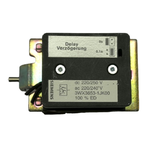
Siemens SION 3AE-Z M30 Installation and user guide

Siemens

Siemens SION 3AE-Z M30 Installation and user guide

Siemens SIRIUS 3RV2 3 Series User manual

Siemens

Siemens SIRIUS 3RV2 3 Series User manual

Siemens Sentron 3VA9157-0FK Series User manual

Siemens

Siemens Sentron 3VA9157-0FK Series User manual

Siemens 8DJH Manual

Siemens

Siemens 8DJH Manual

Siemens SIPLUS HCS POM4320 Highend Administrator guide

Siemens

Siemens SIPLUS HCS POM4320 Highend Administrator guide

Siemens SIRIUS 3RV2.4 User manual

Siemens

Siemens SIRIUS 3RV2.4 User manual

Siemens SENTRON VL Series User guide

Siemens

Siemens SENTRON VL Series User guide

Siemens 3WN6 User manual

Siemens

Siemens 3WN6 User manual

Siemens 3AH6 User manual

Siemens

Siemens 3AH6 User manual

Siemens RL Series User manual

Siemens

Siemens RL Series User manual

Siemens Sentron 3VA91 8-0VF30 Series User manual

Siemens

Siemens Sentron 3VA91 8-0VF30 Series User manual

Siemens 3VA20-H 3 Series User manual

Siemens

Siemens 3VA20-H 3 Series User manual

Siemens Sentron 3VA9157-0PK1 Series User manual

Siemens

Siemens Sentron 3VA9157-0PK1 Series User manual

Siemens 3VF 9 624-1FA.0 User manual

Siemens

Siemens 3VF 9 624-1FA.0 User manual

Popular Circuit Breaker manuals by other brands

Rittal SV 9677.000 Assembly and operating instructions

Rittal

Rittal SV 9677.000 Assembly and operating instructions

SIMiONIC SHCB01 user manual

SIMiONIC

SIMiONIC SHCB01 user manual

ABB SACE Emax 2 manual

ABB

ABB SACE Emax 2 manual

Eaton QSA40N0 Series Instruction leaflet

Eaton

Eaton QSA40N0 Series Instruction leaflet

ETI ETIBREAK NBS 160 Assembly instruction

ETI

ETI ETIBREAK NBS 160 Assembly instruction

Eaton JDB installation instructions

Eaton

Eaton JDB installation instructions

LS ELECTRIC Susol Series instruction manual

LS ELECTRIC

LS ELECTRIC Susol Series instruction manual

Schrack BES2 Series operating instructions

Schrack

Schrack BES2 Series operating instructions

Westinghouse DB-75 manual

Westinghouse

Westinghouse DB-75 manual

FEDERAL PIONEER H-3 INSTRUCTIONS FOR THE CARE AND MAINTENANCE

FEDERAL PIONEER

FEDERAL PIONEER H-3 INSTRUCTIONS FOR THE CARE AND MAINTENANCE

hager Muse installation manual

hager

hager Muse installation manual

hager HX 830 quick start guide

hager

hager HX 830 quick start guide

Eaton IZM Series Installation and Removal Instructions

Eaton

Eaton IZM Series Installation and Removal Instructions

ABB SACE Emax 2 manual

ABB

ABB SACE Emax 2 manual

Phoenix Contact CBMC E4 24DC/1-10A IOL user manual

Phoenix Contact

Phoenix Contact CBMC E4 24DC/1-10A IOL user manual

Eaton RVU Series operating instructions

Eaton

Eaton RVU Series operating instructions

Leuze electronic MSI-SR-LC21 Series Original operating instructions

Leuze electronic

Leuze electronic MSI-SR-LC21 Series Original operating instructions

ABB eVD4 Installation and service instructions

ABB

ABB eVD4 Installation and service instructions

manuals.online logo
manuals.online logoBrands
  • About & Mission
  • Contact us
  • Privacy Policy
  • Terms and Conditions

Copyright 2025 Manuals.Online. All Rights Reserved.