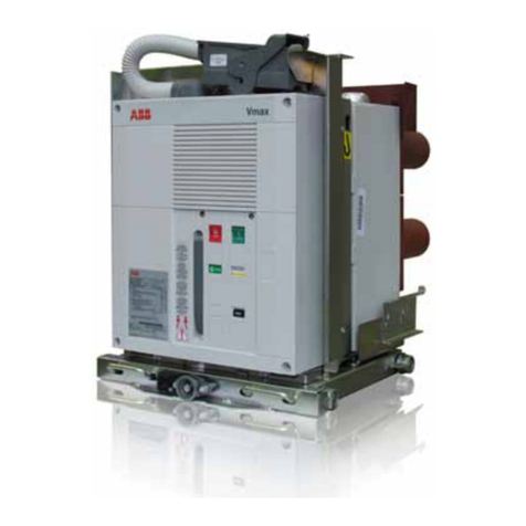
ABB eVD4 Quick guide

Medium voltage products
eVD4
Installation and service instructions
12 ... 17.5 kV - 630 ... 2500 A - 16 ... 40 kA
For your safety! 1
I. Introduction 2
II. Programme for environmental protection 2
1. Packing and transport 3
2. Checking on receipt 4
3. Storage 6
4. Handling 7
5. Description 8
5.1. General information 8
5.2. Reference Standards 8
5.3. Composition 8
5.4. Fixed circuit-breakers 26
5.5. Withdrawable circuit-breakers 32
5.6. Characteristics of the electrical accessories 40
6. Instructions for circuit-breaker operation 41
6.1. Safety indications 41
6.2. Operating and signalling parts 41
6.3. Circuit-breaker closing and opening operations 42
7. Installation 44
7.1. General information 44
7.2. Installation and operating conditions 44
7.3. Preliminary operations 46
7.4. Installation of fixed circuit-breaker 46
7.5. Installation of withdrawable circuit-breaker in
UniGear ZS1 switchgear and PowerCube units 46
7.6. HMI installation instructions 48
7.7. Power circuit connections of fixed circuit-breakers 49
7.8. Earthing 50
7.9. Connection of the auxiliary circuits 50
8. Putting into service 51
8.1. General procedures 51
9. Maintenance 52
9.1. General information 52
9.2. Inspections and functional tests 52
9.3. Servicing 54
9.4. Repairs 55
10. Application of X-ray emission standards 56
11. Spare parts and accessories 57
11.1. List of spare parts 57
12. Electric circuit diagrams 58
13. Overall dimensions 59
14. Product quality and environmental protection 67


11
• Make sure that the installation room (spaces, divisions
and environment) is suitable for the electrical
apparatus.
• Check that all the installation, putting into service and
maintenance operations are carried out by qualified
personnel with suitable knowledge of the apparatus.
• Make sure that the pertinent standards and laws are
complied with during installation, putting into service
and maintenance, so that the installations conform to
the rules of good working practice and safety in the
work pace.
• Strictly follow the information given in this instruction
manual.
• Check that the rated performance of the apparatus is
not exceeded during service.
• Check that the personnel operating the apparatus
have this instruction manual to hand as well as the
necessary information for correct intervention.
• Pay special attention to the danger notes indicated in
the manual by the following symbol:
Responsible behaviour safeguards your own
and others’ safety!
For any requests, please contact the ABB
Assistance Service.
For your safety!

22
I. Introduction
This publication contains the information needed to install
medium voltage eVD4 circuit-breakers and put them into
service.
For correct use of the product, please read it carefully.
Like all the apparatus we manufacture, the eVD4 circuit-
breakers are designed for different installation configurations.
However, this apparatus allows further technical-construction
modifications (at the customer’s request) to adapt to special
installation requirements.
Consequently, the information given below may sometimes
not contain instructions concerning special configurations.
Apart from this manual, it is therefore always necessary to
consult the latest technical documentation (electric circuit
and wiring diagrams, assembly and installation drawings, any
protection coordination studies, etc.), especially regarding
any variants requested in relation to the standardised
configurations.
Only use original spare parts for maintenance operations.
For further information, please also see the technical
catalogue of the circuit-breaker and the spare parts
catalogue.
All the installation, putting into service, running and
maintenance operations must be carried out by
skilled personnel with in-depth knowledge of the
apparatus.
II. Environmental protection programme
The eVD4 circuit-breakers are manufactured in accordance
with the ISO 14000 Standards (Guidelines for environmental
management).
The production processes are carried out in compliance with
the Standards for environmental protection in terms of
reduction in energy consumption as well as in raw materials
and production of waste materials.
All this is thanks to the environmental management system
utilized in the facility where the medium voltage apparatus is
manufactured.

33
1. Packing and transport
The circuit-breaker is shipped in special packing, in the open
position and with the spring released.
Each piece of apparatus is protected by a plastic cover to
prevent water from infiltrating during the loading and
unloading stages and to keep the dust off during storage.

44
A
B
3
4
2
1
5
C
D
Fig. 1b
A Circuit-breaker rating plate
B Sensor rating plate
C Operating mechanism rating plate
D Configuration code
1 Type of apparatus
2 Symbols of compliance with Standards
3 Serial number
4 Circuit-breaker characteristics
5 Characteristics of the operating mechanism
auxiliaries
2. Checking on receipt
Before carrying out any operation, always make
sure that the spring of the operating mechanism
is released and that the apparatus is in the open
position.
On receipt, immediate check the condition of the packing and
the color of the “SHOCK WATCH” (fig. 1a) impact indicator..
If the “SHOCKWATCH” impact indicator is RED, follow the in-
structions indicated on the plate.
Opening the packing does not damage its components, therefore
it can be remade using the original material supplied.
Also make sure that all the materials described in the shipping
note are included in the supply.
Should any damage or irregularity be noted in the supply
on unpacking, notify ABB (directly or through the agent or
supplier) as soon as possible and in any case within five days
of receipt.
The apparatus is only supplied with the accessories specified
at the time of ordering and validated in the order confirmation
sent by ABB.
The accompanying documents included in the shipping
packing are:
– instruction manual (this document)
– test certification
– identification label
– copy of the shipping documents
– electric wiring diagram.
Other documents which are sent prior to shipment of the
apparatus are:
– order confirmation
– original shipping advice note
– any drawings or documents referring to special
configurations/conditions.
CIRCUIT-BREAKER
eVD4/P 12.06.25
CLASSIFICATION M2
SN 1VC1BA00045139
M WEIGHT 124 kg
Ur VOLTAGE 12 kV
Up LIGHTNING IMPULSE WITHSTAND VOLTAGE 75 kV
Ud POWER FREQUENCY WITHSTAND VOLTAGE 28 kV
fr FREQUENCY 50/60 Hz
Ir THERMAL CURRENT 630 A
A
lk SHORT TIME WITHSTAND CURRENT 25 kA
tk DURATION OF SHORT CIRCUIT 3 s
ISC BREAKING CURRENT 25 kA
MAKING CAPACITY (PEAK VALUE) 63 kA
AT THE VOLTAGE OF 12 kV
D.C. COMPONENT < = 30 %
Ic BREAKING CURRENT FOR NO-LOAD CABLES 25 A
OPERATING SEQUENCE O-0,3S-CO-15S-CO
CURRENT SENSOR IPR:250A CL: 1/5P
KEVCR 17.5 AC1 USR: 0.150/0.180V
EL1 OPERATING MECHANISM
ELECTRICAL DIAGRAM 1VCD400106 (V2970)
FIG. 01 FIG. 56 FIG. 66 FIG. 70 FIG. 75
CONFIGURATION CODE: XAAWILANLNC1
IEC 62271-100
CEI 17-1
IEC 60044-7, -8
IEC 60255-26
PR. YEAR 2010
-MBC -MBO1 -RLE2 -AA 24 ... 60 V
-MAS 220 V 50Hz RBX615
CONFIGURATION CODE: XAAWILANLNC1
Made by ABB Italy
Impact indicator
When the “SHOCKWATCH” impact indicator is WHITE it means
that the packing has not sustained any serious shock during
transport. Open the packing, check the condition of the ap-
paratus and correspondence of the nameplate data (see fig.
1b) with the data specified in the shipping note and in the order
acknowledgement sent by ABB.
Fig. 1a

55
Meaning of the configuration code
The configuration code is a string of characters which briefly describes some of the circuit-breaker characteristics.
Each character represents an individual component or a characteristic.
The table below shows the rules for creating the configuration code. The configuration code is indicated on the rating plate
(fig. 1).
Configuration code
||||||||||||
Presence of I/O extension | | | | | | | | | | | |
NO ------------------------------------------------------------------------------------- N | | | | | | | | | | |
YES ------------------------------------------------------------------------------------ X | | | | | | | | | | |
License level | | | | | | | | | | |
Feeder 1 ----------------------------------------------------------------------------------- A | | | | | | | | | |
Feeder 2 ----------------------------------------------------------------------------------- B | | | | | | | | | |
Feeder 3 ----------------------------------------------------------------------------------- C | | | | | | | | | |
Motor 1 ------------------------------------------------------------------------------------ G | | | | | | | | | |
Motor 2 ------------------------------------------------------------------------------------ H | | | | | | | | | |
Full functionality --------------------------------------------------------------------------- Z | | | | | | | | | |
Communication module type | | | | | | | | | |
Two-channel Ethernet ------------------------------------------------------------------------- A | | | | | | | | |
Two-channel serial ----------------------------------------------------------------------------- B | | | | | | | | |
Two-channel optic fibre ---------------------------------------------------------------------- C | | | | | | | | |
None --- ---------------------------------------------------------------------------------------- N | | | | | | | | |
CB type | | | | | | | | |
Fixed ------------------------------------------------------------------------------------------------- F | | | | | | | |
Withdrawable (manual truck) ----------------------------------------------------------------------- W | | | | | | | |
Withdrawable (motorized truck) -------------------------------------------------------------------- M | | | | | | | |
Rated current of sensors | | | | | | | |
Combisensor -------------------------------------------------------------------------------------------- C | | | | | | |
Current sensor ------------------------------------------------------------------------------------- I | | | | | | |
Voltage range | | | | | | |
LV (48...60 V dc) ---------------------------------------------------------------------------------------------- L | | | | | |
HV (110...250 V dc) ------------------------------------------------------------------------------------------- H | | | | | |
Sensor type | | | | | |
K1 – 250 A -------------------------------------------------------------------------------------------------------- A | | | | |
K2 – K3 – 500 A -------------------------------------------------------------------------------------------------- B | | | | |
-RL1 presence | | | | |
NO --------------------------------------------------------------------------------------------------------------------- N | | | |
Yes ---------------------------------------------------------------------------------------------------------------------- L | | | |
-RL2 presence | | | |
NO --------------------------------------------------------------------------------------------------------------------------- N | | |
Yes ---------------------------------------------------------------------------------------------------------------------------- L | | |
Auto-reclosing | | |
NO -------------------------------------------------------------------------------------------------------------------------------- N | |
Yes ------------------------------------------------------------------------------------------------------------------------------- L | |
Communication protocol | |
IEC61850+MODBUS ---------------------------------------------------------------------------------------------------------------- C |
IEC61850 ----------------------------------------------------------------------------------------------------------------------------- A |
MODBUS ------------------------------------------------------------------------------------------------------------------------------ B |
MODBUS RTU ------------------------------------------------------------------------------------------------------------------------ D |
DNP3 --------------------------------------------------------------------------------------------------------------------------------- E |
Language |
English ------------------------------------------------------------------------------------------------------------------------------------- 1
English & German ------------------------------------------------------------------------------------------------------------------------- 2
English & Swedish ----------------------------------------- ------------------------------------------------------------------------------- 3
English & Spanish ------------------------------------------------------------------------------------------------------------------------- 4
English & Russian ------------------------------------------------------------------------------------------------------------------------- 5
English & Portuguese (Brazilian) --------------------------------------------------------------------------------------------------------- 6

66
3. Storage
When a period of storage is foreseen, our workshops can (on
request) provide suitable packing for the specified storage
conditions.
On receipt the apparatus must be carefully unpacked and
checked as described in Checking on receipt (chap. 2).
If immediate installation is not possible, the apparatus must
be packed again with the original material supplied.
Insert packets of special hygroscopic substances inside the
packing, with at least one standard packet for piece of
apparatus.
If immediate installation is not possible, store the apparatus
in a covered, well-ventilated, dry, dust-free, non-corrosice
place, well away from any easily flammable materials and
at a temperature between -5 °C and +40 °C (for lower
temperatures, please ask ABB).
Avoid accidental impact or positions that stress the structure
of the apparatus.

77
1
2
3
B
3
CA
Version Pole centre distance Rated current Hole
Fixed 150-210 mm up to 1250 A A
Fixed 275 mm from 1600 to 2500 A A
Fixed 210 mm from 1600 to 2000 A A
Withdrawable 150 mm up to 1250 A A
Withdrawable 210 mm from 1600 to 2000 A B
Withdrawable 275 mm up to 1250 A B
Withdrawable 275 mm from 1600 to 2500 A C
Withdrawable 210 mm up to 1250 A C
4. Handling
Before carrying out any operations, always make sure that the
operating mechanism spring is released and that the
apparatus is in the open position.
To lift and handle the circuit-breaker, proceed as follows (fig. 2):
– use a special lifting tool (1) (not supplied) fitted with ropes
with safety hooks (2);
– insert the hooks (2) in the supports (3) fixed to the frame
of the circuit-breaker and lift. Put the hooks (2) into the
support holes (3) according to the type of apparatus (see
table);
– on completion of the operation (and in any case before
putting into service) unhook the lifting tool (1) and dismantle
the supports (3) from the frame.
During handling, take great care not to stress the insulating
parts and the terminals of the circuit-breaker.
The apparatus must not be handled by putting
lifting devices directly under the apparatus itself.
Should it be necessary to use this technique, put
the circuit-breaker onto a pallet or a sturdy
supporting surface (see fig. 3).
In any case, it is always advisable to carry out
lifting using the supports (3).
Fig. 2
Fig. 3

88
5. Description
5.1. General
The eVD4 series of vacuum circuit-breakers are apparatus
for indoor installation. For the electrical performances, please
refer to the corresponding technical catalogue.
For special installation requirements, please contact ABB.
The following versions are available:
– fixed
– withdrawable for UniGear ZS1 switchgear and PowerCube
units.
Vacuum circuit-breakers have particular advantages when
used in systems with a high operation frequency and/or which
involve a certain number of short-circuit interruptions. The
eVD4 vacuum circuit-breakers comprise the circuit-breaker,
sensor, protection and control functions in a single solution.
eVD4 circuit-breakers include an RBX615 relays and current
and voltage sensors. The multi-function RBX615 unit is
an Intelligent Electronic Device (IED), has a vast range of
protection and control functions and makes the eVD4 a
complete product, able to satisfy the needs of modern electric
installations.
The “combisensor” version sensors allow simultaneous and
precise measurements of both current and voltage. Integration
of the multi-purpose electronics and of the sensors on board
the circuit-breaker is done in the factory and is followed
by a careful testing stage which allows the functionality
of the whole system to be checked before the product is
sold. These checks, together with the many self-diagnosis
functions of the IED make the eVD4 stand out for their highly
reliable operation and low maintenance required.
eVD4 vacuum circuit-breakers are derived from the VD4
series of which they possess the same reliability and sturdy
construction.
5.2. Reference standards
The eVD4 vacuum circuit-breakers conform to the
specifications of the following Standards:
– IEC 62271- 100 VDE 0670 part 1000
– IEC 62271-1 DIN VDE 0670 part 104
– IEC 61000-4 DIN VDE 0847 part 4
– IEC 60255-26
– IEC 60044 -7 -8
5.3. Composition
The eVD4 circuit-breaker is a system consisting of:
– vacuum circuit-breaker with mechanical stored energy and
free release operating mechanism (5)
– RBX615 electronic unit to carry out the protection, control,
measurement, monitoring and self-diagnosis functions (3)
– embedded sensors for current and voltage measurement (2)
– Human Machine Interface (HMI), allowing all the RBX615
functions to be managed from the low voltage compartment
door.
– Web HMI, allowing most of the HMI functions to be used by
means of
a web browser.
The actuator works on the circuit-breaker poles by means of
special kinematics. The operating mechanism springs provide
the energy needed to activate the driving gear.
The circuit-breaker operating position is monitored thanks to
two inductive sensors
The basic circuit-breaker version also has the following
instruments:
– manual device for loading the operating mechanism
– mechanical open/closed state indicator
– mechanical indicator of springs loaded
– mechanical operation counter
– opening and closing pushbuttons.
The withdrawable version has a truck (15), either manual or
motorized, consisting of a steel sheet structure with wheels,
on which the circuit-breaker is installed with the relative
auxiliary components, the isolating contacts for electric
connection with the switchgear and the multi-pole connector
for connection of the circuit-breaker auxiliary circuits.
After being racked into the switchgear and hooked up,
the withdrawable circuit-breaker functions in the following
positions: racked-out, isolated for test (with the connector
inserted) and racked-in.
The racked-in circuit-breaker is automatically earthed by
means of the truck wheels.
The mechanical actuator of the circuit-breaker and the relative
operating pushbuttons are accessible from the front.
Withdrawable circuit-breakers of the same type and
characteristics are interchangeable, but the connector coding
prevents incorrect combinations between circuit-breaker and
switchgear.
5.3.1. Structure
Fixed circuit-breaker (fig. 4/a)
Withdrawable circuit-breaker (fig. 4/b).
99
8-10
11
12
14
6
4
2-10
1-8-10
9
13
5
3
7
17
17
8-10
15
18
14
6
4
2-10
1-8-10
9
13
5
3
7
17
19
20
16
21
1 Opening pushbutton
2 Closing pushbutton
3 Lever for manual closing spring loading
4 Signalling device for closing spring loaded (yellow) and released (white)
5 Signalling device for circuit-breaker open/closed
6 Operation counter
7 Key lock in the open position (on request)
8 Padlock in the open position (on request)
9 Connector (Plug)
10 Pushbutton protection (on request)
11 M12 fixing devices (250x400)
12 Earth terminal M12
13 Electronics
14 Current and voltage sensors
15 Motorized truck on request for UniGear panels
16 Centring pins
17 Signalling LED
18 Slides for operating the switchgear shutters
19 Locks for hooking into the fixed part
20 Handles for activating the locks (19)
21 Isolating contacts
22 Operating lever
Fig. 4b Withdrawable circuit-breaker
Fig. 4a Fixed circuit-breaker

1010
1
4
5
7
8
9
10
6
2
3
1
2
3
4
5
6
7
8
10
9
5.3.2. Poles
The eVD4 series vacuum circuit-breaker has poles with the
vacuum interrupter embedded in resin or thermoplastic
material. Embedding the interrupter makes the circuit-breaker
poles particularly sturdy and protects the interrupter against
shocks, dust deposits and humidity.
The vacuum interrupter houses the contacts and forms the
interruption chamber.
The vacuum circuit-breaker does not require any interruption
and insulating means. In fact, the interrupter does not contain
ionisable material.
When the contacts separate, an electric arc formed only by
fusion and vaporization of the contact material is generated
in any case. The electric arc is sustained by the external
energy until the current is nullified near its natural zero. At
that instant, the sharp reduction in the density of the charge
conveyed and rapid condensation of the metallic vapour very
rapidly leads to the dielectric properties being restored.
1 Upper terminal
2 Vacuum interrupter
3 Housing/pole
4 Stem of moving contact
5 Lower terminal
6 Flexible connection
7 Tie-rod spring fork
8 Tie-rod
9 Pole fixing
10 Connection to operating
mechanism
Vacuum interrupter embedded in the pole.
1 Terminal
2 Protection
3 Metal bellows
4 Interrupter housing
5 Shield
6 Ceramic insulator
7 Shield
8 Contacts
9 Terminal
10 Interrupter housing
Vacuum interrupter.
Embedded pole with vacuum interrupter.
The vacuum interrupter therefore recovers its insulating
capacity and the capacity to sustain the transient return
voltage, definitively extinguishing the arc.
Since a high dielectric strength can be reached in the vacuum
even with minimum distances, circuit breaking is guaranteed
even when separation of the contacts takes place a few
milliseconds before the current passes through natural zero.
The particular geometry of the contacts and of the material
used, together with reduced duration of the arc and the
low arcing voltage, ensure minimum contact wear and a
long life. Moreover, the vacuum prevents their oxidation and
contamination.
For the trip curves, see paragraph 7.2.3.

1111
5.3.3 Breaking principle
In a vacuum interrupter, the electric arc begins at the instant
the contacts separate, persists until zero current is reached
and can be influenced by the magnetic field.
Diffuse or contracted vacuum arc
Individual points of fusion form on the surface of the cathode
following separation of the contacts. This leads to formation
of metallic vapours that support the arc itself.
The diffuse arc is characterized by expansion over the surface
of the contact and by evenly distributed thermal stress.
The electric arc is always the diffuse type at the rated current
value of the interrupter. There is very little erosion of the
contact and a very high number of interruptions.
As the value of the interrupted current increases (beyond the
rated value), the electric arc tends to change from diffuse to
contracted owing to the Hall effect.
Starting from the anode, the arc contracts and tends to
concentrate as the current increases. There is a temperature
increase in the affected area, and the contact is therefore
subjected to thermal stress.
To prevent the contacts from overheating and becoming
eroded, the arc is kept rotating. By rotating, the arc resembles
a moving conductor through which the current passes.
Development of current and voltage trends during a single phase vacuum interruption process.
Radial magnetic field contact
arrangement with a rotating
vacuum arc.
Recovery voltage
(system frequency)
Transient recovery voltage (TRV)
(high frequency)
Time
Current, Voltage
System voltage
Contact
separation
Arc voltage
Short-circuit current
interruption
Current of
short-circuit
Spiral geometry of ABB interrupter contacts
The special geometry of the spiral contacts generates a radial
magnetic field in all areas of the arc column, concentrated
over the contact circumferences.
An electromagnetic force is self-generated and this acts
tangentially, causing rapid arc rotation around the contact
axis.
This means the arc is forced to rotate and to involve a wider
surface than that of a fixed contracted arc.
Apart from minimising thermal stress on the contacts, all this
makes contact erosion negligible and, above all, allows
the interruption process to be controlled even with very high
short-circuits.
ABB vacuum interrupters are zero-current interrupters and are
free of any re-striking.
Rapid reduction in the current charge and rapid condensation
of the metal vapours simultaneously with the zero current,
allows maximum dielectric strength to be restored between
the interrupter contacts within a few microseconds.
Schematic diagram of the transition from a diffuse arc to a contracted arc
in a vacuum interrupter.
Diffuse arc. Contraction
over anode.
Contraction over anode
and cathode.

1212
Versions available
The eVD4 circuit-breakers are available in the fixed and
withdrawable version with front operating mechanism.
The withdrawable version is available for UniGear ZS1
switchgear and PowerCube units.
Fields of application
The eVD4 circuit-breakers are used in power distribution for
control and protection of cables, overhead lines, transformer
and distribution substations, motors, transformers, generators
and capacitor banks.
Standards
The eVD4 circuit-breakers comply with the IEC 62271-100,
VDE 0671-part.100, CEI17-1-file 1375 Standards and those
of major industrialised countries.
The eVD4 circuit-breakers have undergone the tests indicated
below and guarantee the safety and reliability of the apparatus
in service in any installation.
• Type tests: heating, withstand insulation at power
frequency, withstand insulation at lightning impulse,
short-time and peak withstand current, mechanical life,
short-circuit current making and breaking capacity and
interruption of vacuum cables.
• Individual tests: insulation of the main circuits with
voltage at power frequency, auxiliary circuit and operating
mechanism insulation, measurement of the main circuit
resistance, mechanical and electrical operation.
Service safety
Thanks to the complete range of mechanical and electrical
locks (available on request), it is possible to construct safe
distribution switchgear with the eVD4 circuit-breakers.
The locking devices have been designed to prevent incorrect
operations and allow the installations to be inspected whilst
guaranteeing maximum operator safety.
Key locks or padlocks enable opening and closing operations
and/or racking in and racking out.
The racking-out device with the door closed only allows the
circuit-breaker to be racked into or out of the switchgear only
with the door closed.
Anti-racking-in locks prevent circuit-breakers with different
rated currents from being racked in, and the racking-in
operation with the circuit-breaker closed.
The operating mechanism is of mechanical stored energy and
free trip type. These characteristics allow opening and closing
operations independent of the operator. The open/closed and
springs loaded/released states are visible from the front of
the circuit-breaker and are detected by the relay by means of
inductive proximity sensors.
The operating mechanism is of very simple conception,
characterised by few components and great reliability.
It can be customised with a wide range of accessories which
are easy and rapid to install.
5.3.5. Position and springs loaded sensors
The use of two inductive position sensors allows the circuit-
breaker state (open - closed – intermediate anomalous
position) to be detected without using auxiliary contacts,
allowing continuous monitoring of the system.
A further inductive sensor detects whether the spring is
completely loaded.
Open-closed, spring loaded/released proximity sensors.
5.3.4 EL operating mechanism
The eVD4 circuit-breakers are equipped with an EL spring
operating mechanisms.
The EL operating mechanism is designed to cover the range
of circuit-breakers indicated in the following table.
Type of operating mechanism Breaking capacity
EL1 - EL2 up to 31.5 kA
EL3 up to 40 kA

1313
Ip (log)
Uout
Up
uout = M dip
dt
1000
100
10
1
0,1
0,01
0,01 10,1 100010010
Current sensors
without ferro-
magnetic nucleus
Current transformers
with ferromagnetic
nucleus
Saturation
secondary current
primary current
General diagram of the Rogowski coil (current sensor).
Extent of error “ε”made by the current sensors and by traditional current
transformers.
Combined current voltage sensor applied to the circuit-breaker poles.
5.3.6. Current and voltage sensors
– Rogowski sensors: only for current measurement in the
versions of eVD4 where voltage measurement is not
required.
– Combisensor sensors: allow current and voltage
measurement. Together with the Rogowski coil they
integrate a capacitive divider for measuring the voltage
applied to each pole.
This new generation of sensors is characterised by limited
dimensions, better performance compared to traditional
current and voltage transformers and a higher degree of
standardization.
5.3.6.1 Rogowski coils
A uniform winding on a closed circular support with a
constant cross section and without the ferromagnetic core.
The voltage induced in the winding is directly proportional to
the let-through current variation.
There are many advantages provided by using the Rogowski
coil, among which are:
– absolute linearity of the output signal according to the one
measured
– no saturation
– no currents magnetizing the metal nucleus, which is
important at low values for the current transformers
– no hysteresis phenomena.
These characteristics allowed the eVD4 circuit-breaker to be
designed with just three sensor sizes able to cover all rated
current values from 50 to 2500 A, and to protect against
short-circuits up to 40 kA.
Response characteristic of the Rogowski coil compared with that of a cur-
rent transformer.
Precision limit
Current
sensor
Rated
current
Current
transformer

1414
uout = up
C1
C1 + C2
Uout
Up
General diagram of the capacitive divider (voltage sensor).
The extent of error “ε” made by the Rogowski current sensors
is constant and independent of the primary current value.
This means the error can be eliminated with an appropriate
characteristic correction factor of the sensor. Traditional
current transformers have an error which depends on the
primary current. For this reason, the error committed is not
constant so cannot be corrected and, furthermore, takes on
substantial values at the extremities of the primary current
application range.
Since they are fully integrated and tested in the factory,
the eVD4 circuit-breakers take advantage of this concept
to obtain an excellent measurement performance. During
production of each eVD4 the RBX615 is calibrated with the
characteristic correction factors of the current and voltage
sensors mounted on that particular circuit-breaker.
5.3.6.2 Capacitive divider
The capacitive element is made up of a cylindrical metal
surface, facing the circuit-breaker bushing. The output signal
is a voltage directly proportional to the primary voltage.
The voltage sensors are characterized by absence of any
ferroresonance phenomena and their insensitivity to the
effects of the direct components. A single divider covers
the service range of voltages up to the rated voltage of the
circuit-breaker.
5.3.6.3 Types and characteristics of the sensors used in
the eVD4 circuit-breaker
eVD4 circuit-breakers, which do not include voltage
measurement, use KEVCR AC1 and KEVCR BC1 current
sensors with rated currents of 1250, 2000 and 2500 A
respectively.
KEVCR AA1 and KEVCR BA1 type sensors are used for the
eVD4 with voltage measurement.
Sensor voltage accuracy voltage data current accuracy current data
K1 COMBISENSOR KEVCR 17.5 AA1 Kn 10000: 1 cl: 1/3P Ku 1.9/8h Ipr: 250A cl: 1/5P Usr: 0.150/0.180V
CURRENT SENSOR KEVCR 17.5 AC1 – – – Ipr: 250A cl: 1/5P Usr: 0.150/0.180V
K2 COMBISENSOR KEVCR 17.5 BA1 Kn 10000: 1 cl: 1/3P Ku 1.9/8h Ipr: 500A cl: 1/5P Usr: 0.150/0.180V
CURRENT SENSOR KEVCR 17.5 BC1 – – – Ipr: 500A cl: 1/5P Usr: 0.150/0.180V
K3
COMBISENSOR KEVCR 17.5 CA1 Kn 10000: 1 cl: 1/3P Ku 1.9/8h Ipr: 500A cl: 1/5P Usr: 0.150/0.180V
CURRENT SENSOR KEVCR 17.5 CC1 – – – Ipr: 500A cl: 1/5P Usr: 0.150/0.180V

1515
RBX615
1
2
5.3.7 RVX615 protection and control unit
RBX615 is a line protection relay dedicated to protection,
measurement and monitoring of utility substations and
industrial electrical systems.
The new protection relay has been designed to implement the
whole potential of the IEC 61850 Standard on the subject of
communication and interoperability of the automation devices
for substations.
The RBX615 relay guarantees general protection of overhead
lines, cable lines and busbar systems of distribution
substations and adapts to any radial distribution network
regardless of the earthing principle.
To dismantle it, after having removed the front screen, simply
unscrew the screws in pos. 1 and extract the device.
To assemble it, insert the device making sure that it couples
correctly and fully into the fixed part and tighten the screws
(1) complete with spring washers (2) applying a tightening
torque of 1.5 N/m.
N.B. Before carrying out this operation, make sure
that the circuit-breaker is open with the springs
released, and disconnected from the main circuit
and from the auxiliary power supply.
5.3.7.1 Protection and control
The RBX615 relay offers protection against short-circuit,
directional and non-directional protection, overcurrent
protection with definite delay trip and protection against
thermal overload.
It also has a directional and non-directional earth fault
protection, a protection against sensitive earth fault (SEF)
and a protection against earth fault with measurement of the
transients, including detection of intermittent earth faults in
wired networks, as well as an overvoltage and undervoltage
protection.
Finally, the relay includes a flexible automatic multiple
reclosing function to eliminate faults due to an arc on
overhead lines.
Apart from the series of line protections, the RBX615 relay
offers protection for motors against phase reversal and
thermal overload, monitoring of the number of start-ups and
of rotor block.
The RBX615 relay includes basic functions which make
control of a circuit-breaker easier by means of the relay HMI
or a remote control system. To protect the relay against
access by unauthorized people and to maintain the integrity of
information, the relay is provided with a user authentication
system based on four-level role, with individual passwords for
the inspector, operator, technician and administrator levels.
Access control applies to the front of the HMI (Human
Machine Interface), to the HMI based on the web browser and
to the configuration and setting tool for relay PCM600.

1616
Plug of the circuit-breaker auxiliary circuits and for RBX615 unit communi-
cation towards the switchgear.
5.3.7.2 Standardized communication
The RBX615 unit supports the new IEC 61850 communication
Standard regarding devices in substations.
It also supports standard industrial protocols such as
Modbus® TCP/IP and RTU.
Implementation of the IEC 61850 communication Standard
for substations in the RBX615 unit, includes both vertical
communication (towards the substation network) and
horizontal communication (between the switchgear relays),
among which are communication by means of GOOSE
messaging and parameter setting according to the IEC
61850-8-1 Standard.
5.3.7.3 Virtual GOOSE wiring for interlock
Implementation of the IEC 61850 Standard in the RBX615
relay also includes rapid horizontal relay-relay communication
by means of the station bus. By using GOOSE communication
(Generic Object Oriented Substation Event), the RBX615
relay of the incoming and outgoing lines of a substation
operates in synergy so as to form a stable, reliable and
high speed protection system. Protection based on GOOSE
communication is obtained simply by configuring the relays.
The operating availability of the protection is guaranteed by
constant monitoring of the protection relays and their GOOSE
communication by means of the station bus. Separate
physical wiring is not required for horizontal communication
among the switchgear units.
5.3.7.4 Preventive status monitoring
To guarantee operative availability of the protection, the
RBX615 relay includes a wide range of monitoring functions
to supervise the hardware and software, communication, the
circuit-breaker trip circuit and the circuit-breaker itself.
Depending on the configuration selected, the relay monitors
the state of wear of the circuit-breaker and the time for
loading the circuit-breaker operating mechanism springs.
The relay also measures the operation time and counts the
number of circuit-breaker operations, therefore collecting the
basic information to program suitable maintenance.
5.3.7.5 Rapid configuration and putting into service
Thanks to the standard pre-configurations available, the
RBX615 unit can be configured and put into service extremely
rapidly once the specific application settings have been
defined.
The standard pre-configurations are easily customisable by
means of the PCM600 ACT (Application Configuration Tool)
software, by means of which the user can create complex
logics according to the specific substation requirements.
The high degree of flexibility and configurability of the
protection and control unit makes the eVD4 circuit-breaker
very versatile and suitable for all types of use.

1717
5.3.7.6 Distinctive features of the RBX615 relay
– Protection against earth fault and of the directional and
non-directional phase, protection against sensitive earth
fault and protection against earth fault with measurement of
the transients, also effective against intermittent earth faults
on wired lines
– Full specific protection of motors
– Series of voltage protections
– Connectivity of the device and interoperability of the system
according to the IEC 61850 Standard for communication
between substations
– Thanks to the GOOSE communication, physical copper
wiring among the switchgear units is not necessary to
obtain a high speed interlock
– More powerful functionality of the oscilloperturbograph.
High sampling frequency, increased quantity of recordings,
analogue and binary channels and flexible activation
principle.
– A single device for setting the relay, configuring the signals
and managing the fault recorder.
5.3.7.7 Binary inputs and outputs
Thanks to an optional digital I/O card, the RBX615 unit
provides a total of 10 binary inputs and 6 binary outputs that
can be, freely programmed by the user, plus a further 7 inputs
and 6 outputs assigned to predefined functions.
The binary inputs and outputs of the relay are available in the
low voltage compartment of the switchgear by means of the
circuit-breaker plug-socket contacts.
eVD4 makes three communication modules:
– Ethernet RJ45 electrical communication
– RS485 serial electrical communication
– Ethernet LC optical communication.
The module is available with single and double door, which
allows a physical communication redundancy to be made.
The communication ports are available in the low voltage
compartment of the switchgear by means of the appropriate
circuit-breaker plug connectors.
The Ethernet port available on the front of the LHMI allows a
point-to-point connection to be made between a PC and the
RBX615 multi-purpose unit.
This port allows use of the WHMI (Web Human Machine
Interface) and full control of the RBX615 unit by means of the
PCM600 configurator.
5.3.7.8 Auxiliary power supply
Type LV: 48-60 V d.c.
Type HV: 110-250 V d.c.
5.3.7.9 Additional devices
PCM600 ver. 2.3 or higher for setting, signal configuration and
recorder management.
User interface based on the web browser (lE 7.0 or higher).
PCM600 and the Application Configuration Tool.

1818
5.3.7.10. Characteristics and configuration settings of the relay
Standard Pre-confìgurations
The RBX615 protection and control unit is available with five alternative pre-configurations.
Description Configuration
Non-directional overcurrent protection and non-directional earth fault protection Feeder 1 (F1)
Non-directional overcurrent protection and directional earth fault protection based on measurement of the phase
voltages Feeder 2 (F2)
Directional overcurrent protection, directional earth fault protection based on measurement of the
phase voltages and undervoltage and overvoltage protection Feeder 3 (F3)
Motor protections based on measurement of the currents Motor 1 (M1)
Motor protections based on measurement of the current and voltages Motor 2 (M2)
Functions IEC 61850 IEC 60617 IEC - ANSI Pre-configurations
F1 F2 F3 M1 M2
Performance
Three-phase overcurrent, non-directional, first threshold PHLPTOC1 3I> (1) 51P-1 (1) • • - • •
Three-phase overcurrent, non-directional, second threshold PHHPTOC1 3I>> (1) 51P-2 (1) • • - - -
PHHPTOC2 3I>> (2) 51P-2 (2) • • - - -
Three-phase overcurrent, non-directional, third threshold PHLPTOC1 3I>>> (1) 50P/51P (1) • • • • •
Three-phase overcurrent, directional, first threshold DPHLPDOC1 3I> → (1) 67-1 (1) - - • - -
DPHLPDOC2 3I> → (2) 67-1 (2) - - • - -
Three-phase overcurrent, directional, second threshold DPHHPDOC1 3I>> →67-2 - - • - -
Earth fault, non-directional, first threshold EFLPTOC1 I0> (1) 51N-1 (1) • - - • -
EFLPTOC2 I0> (2) 51N-1 (2) • - - - -
Earth fault, non-directional, second threshold EFHPTOC1 I0>> (1) 51N-2 (1) • • • • •
Earth fault, non-directional, third threshold EFIPTOC1 I0>>> (1) 50N/51N (1) • - - - -
Earth fault, directional, first threshold DEFLPDEF1 I0> → (1) 67N-1 (1) - • • - •
DEFLPDEF2 I0> → (2) 67N-1 (2) - • • - -
Earth fault, directional, second threshold DEFHPDEF1 I0>> →67N-2 - • • - -
Protection against reverse sequence overcurrent NSPTOC1 I2> (1) 46 (1) • • • • •
NSPTOC2 I2> (2) 46 (2) • • • • •
Protection against phase discontinuity PDNSPTOC1 I2/I1 46PD • • • - -
Residual overvoltage
ROVPTOV1 U0> (1) 59G (1) - • • - -
ROVPTOV2 U0> (2) 59G (2) - • • - -
ROVPTOV3 U0> (3) 59G (3) - • • - -
Three-phase undervoltage
PHPTUV1 3U< (1) 27 (1) - - • - •
PHPTUV2 3U< (2) 27 (2) - - • - -
PHPTUV3 3U< (3) 27 (3) - - • - -
Three-phase overvoltage
PHPTOV1 3U> (1) 59 (1) - - • - -
PHPTOV2 3U> (2) 59 (2) - - • - -
PHPTOV3 3U> (3) 59 (3) - - • - -
Protection against three-phase positive sequence undervoltage PSPTUV1 U1< 47U+ - - • - •
Protection against three-phase negative sequence undervoltage NSPTOV1 U2> 47O- - - • - •
Three-phase thermal line, cable and distribution transformer overload T1PTTR1 3Ith>F 49F • • • - -
Protection against reverse sequence overcurrent for motors MNSPTOC1 I2>M (1) 46M (1) - - - • •
MNSPTOC2 I2>M (2) 46M (2) - - - • •
Protection against under-power LOFLPTUC1 3I< 37 - - - • •
Rotor block JAMPTOC1 Ist> 51LR - - - • •
Motor start-up STTPMSU1 Is2t n< 49.66.48.51LR - - - • •
Protection against phase reversal PREVPTOC I2>> 46R - - - • •
Protection against three-phase thermal overload, for motors MPTTR1 3Ith>M 49M - - - • •
Circuit-breaker fault CCBRBRF1 3I>/I0>BF 51BF/51NBF • • • • •
Three-phase inrush current detector INRPHAR1 3I2f> 68 • • • - -
Trip management TRPPTRC1 Master Trip (1) 94/86 (1) • • • • •
TRPPTRC2 Master Trip (2) 94/86 (2) • • • • •
• available
on request
Other manuals for eVD4
1
Table of contents
Other ABB Circuit Breaker manuals

ABB
ABB Mechanism HMB-8 User manual

ABB
ABB DB BREAKER User manual

ABB
ABB SACE Emax 2 E2.2 Installation instructions

ABB
ABB SACE Emax 2 User manual

ABB
ABB VBF Series Guide

ABB
ABB K-Line Plus KP-8 Installation and operating instructions

ABB
ABB SACE Emax E1 User manual

ABB
ABB SACE Tmax T6 User manual

ABB
ABB AC500 V3 User manual

ABB
ABB S 280 UC Series Instruction manual
Popular Circuit Breaker manuals by other brands

Siemens
Siemens MBKVA5262A Series installation instructions

TERASAKI
TERASAKI TemBreak PRO T2MS4 instruction manual

OEZ
OEZ ARION WL Instructions for use

brennenstuhl
brennenstuhl BDI-S 30 V2 Directions for use

Allen-Bradley
Allen-Bradley 194E installation instructions

Westinghouse
Westinghouse DH-P Series instructions