manuals.online logo
Brands
  1. Home
  2. •
  3. Brands
  4. •
  5. Siemens
  6. •
  7. Control Panel
  8. •
  9. Siemens Apogee P1 User manual

Siemens Apogee P1 User manual

1BOE11BOFMCPBSET
4FMFDUJPO"QQMJDBUJPO(VJEF
&OHJOFFSFEGPSMJHIUJOHBOEQPXFSBQQMJDBUJPOT
1BOE11BOFMCPBSET
s
For more information on products and warranties contact your local distributor or visit: www.purgethesurge.ca
Home Entertainment-
Kitchen & Laundry Appliances-
Home Security Systems-
Computer Systems-
Cable TV / Satellite-
Phone Lines & more-
All Appliances Phone
Coax
Purge damaging surges at the source and protect home electronics
with Siemens SPD
www.purgethesurge.ca
www.siemens.ca
1-888-333-3545
Siemens SPD
TOTAL HOME
SURGE PROTECTION
1
Panelboards
Reference Guide
Features
Siemens offers a complete line of
lighting and power distribution
panelboards, along with a full range of
fusible and circuit breaker devices. Also,
two and three pole breakers are
physically interchangeable with an
equivalent number of one pole breakers.
Lighting Panels
General – P1/P2: Interiors have the
ability to physically interchange two and
three pole breakers with an equivalent
number of one pole breakers. Panels
come standard with connectors suitable
for connection to copper or aluminum
cable. Panel interiors have adjustment
screws to provide easy alignment for
flush mounted applications. The interior is
provided with wing nuts for securing to
box without tools. Removable end walls
are standard and available blank and with
KO's. Panelboard box has a separate CSA
label and supplies wire bending and gut-
ter requirements to meet CSA standards.
Wiring gutters are completely free of any
part of trim clamp to prevent damaging
wire insulation. Deadfronts are provided
with a flange for easy attachment of trim.
Incoming cable lugs are grouped at one
end to separate them from the load side
cables. Individual circuit number button
with an embossed number next to each
breaker or provision are provided. The
interior shall be provided with wing nuts
for securing to box without tools. The
panel trim may be surface or flush and
is equipped with concealed hinges, flush
lock and a holder for circuit directory
card. Trim shall have two separate
supports designed to engage the box
flange to stabilize and secure the trim
during installation. Trim screws are
located behind the lockable door for
tamper resistance.
Interior – Type P1: Interiors may be
completely factory-assembled. Interiors
permit installation of feed-thru lugs or
a bus fed subfeed circuit breaker, up to
600 amperes, without increasing the
enclosure size. Interiors are
convertible from main lug to main
breaker with the addition of an
appropriate field-installable kit. Interior
are changeable from top to bottom feed
and vice-versa, while maintaining read-
ability of dead-front labeling. Main lugs
up to 350 mcm are lay-in construction to
facilitate connections. Neutral bussing is
located adjacent to the breaker load
terminals for easy wiring and shortest
cable run possible.
Interior – Type P2: Interiors are
completely factory-assembled. Incoming
cable lugs are grouped at one end to
separate them from the load side cables.
For easy wiring and shortest cable run
possible, load side neutral connection
lugs to be split with each side taking
50% of load neutral connections.
Application
Lighting:
Control centers for lighting and power
circuits in commercial and industrial
installations as well as residential where
extensive electrical systems are involved.
Power and Distribution — Control
centers for power and distribution circuits
as well as service equipment in larger
commercial and industrial installations.
Ratings
P1/P2: 1 phase, 3 wire,
3 phase, 3 or 4 wire; 120 through
600 Volts AC; 250 Volts DC; 125–600
amperes; main lug only, 50–600 amperes
main breakers; 600 amperes maximum
branch.
Specifications: All panelboards are
listed by Underwriters' Laboratories, Inc.
Interiors are listed under File #E2269.
Boxes and fronts are listed under
file #E4016 & CSA File #LR93833
Standards: Interiors – UL 67, NEMA
PB1 & CSA C22.2 No. 29
Enclosures – UL 50, NEMA
250 & CSA C22.2 No. 0.12
Circuit Breaker
Lighting Panelboard
Types P1
Circuit Breaker
Lighting Panelboard
Type P2
2
Introduction
P1 Panelboards
Key Panelboard Features
Lighting and Appliance Applications
Power Panelboard Applications
Convertible From Top Feed to Bottom Feed and Vice Versa
Change From Main Lug to Main Breaker or Add Sub-Feed Without
Changing Enclosure Size
Space-Saving, Horizontally Mounted Main Breaker Through 250 Amps
Short-Circuit Rating Label Giving Performance Level
Standard Aluminum Ground Bus
Bolted Current-Carrying Parts
Split Neutral
Connection Accessible From Front
Screw-Type Mechanical Lugs
Time-Reducing Wing Nuts to Secure Interior WithoutTools
200 Ampere Rated Branch Breaker Connector
Main and Branch Devices Connected With Case-Hardened Hardware
Flush Lock, Concealed Door Hinges/Trim Screws
Symmetrical Interior Mounting Studs to Eliminate
Upside-Down Mounting of Box
Jacking Screw Interior Adjustment
Shallow Depth
Optional Compression Lugs
Service Entrance Barrier
Single and Double Drip Shield Kits
Blank End-Walls Standard
A product of outstanding quality, the current family
of panelboard designs represents the high level of
engineering innovation expected from Siemens.
Additional strength has been added to an already
rugged and durable panelboard family. At the same time,
many models have a trimmed exterior size, have added
flexibility and are easier to install. These newer designs
simplify wiring and reduce material requirements, saving
additional installation time.
The lighting panel design still features the Fas-Latch
trim that is so popular with installers, the jacking screw
system that permits adjustments even after wiring has
been installed, and other features such as exclusive split
neutral. Many panelboards have the capability of mixing
and matching breakers of different sizes and ratings, or
changing from main lug to main breaker, or adding sub-
feed breakers without changing box size.
The complete family of panelboards from Siemens
employs numerous features – all industry-leading, many
exclusive. Note the following, all found in the innovative
P1 lighting panelboards:
t 4ZNNFUSJDBMJOUFSJPSToOPUPQPSCPUUPN5PDIBOHF
from top to bottom (or vice versa), simply invert the
interior. The deadfront labeling is always right-side up.
t 'JSTUJOUIFJOEVTUSZSBUJOHTPG""NBJOMVH
and main breaker.
t 'JFMEDPOWFSUJCMFGSPNNBJOMVHUPNBJOCSFBLFSBOE
vice versa, with no increase in enclosure height.
t 'JFMEBEEBCJMJUZPGGFFEUISVMVHTPSTVCGFFEDJSDVJU
breaker without increasing enclosure size.
t /FVUSBMTZTUFNJTGJFMEVQHSBEFBCMFUPDBQBDJUZ
– another industry first.
t 5ISFFDJSDVJUTJ[FTNFBOPOMZUISFFCPY
heights, regardless of main configuration through 250
 BNQTBOEBOBEEJUJPOBMDJSDVJUWFSTJPO
 BWBJMBCMFBUBNQT
t 4VJUBCMFGPSVTFBTTFSWJDFFOUSBODFHJWFO
compliance with CEC.
t #POEJOHQSPWJTJPOTBSFTIJQQFEXJUIFBDIQBOFM
t 7BOE:7WFSTJPOTVUJMJ[FJEFOUJDBM
boxes and fronts.
P1 Feature Overview

Panelboard General Specifications
Class CTL Panelboards
Class CTL panelboards incorporate physical features which, in
conjunction with the physical size, configuration, or other means
provided in Class CTL circuit breakers, are designed to prevent the
installation of more overcurrent protective poles than that number
for which the device is designed and rated.
Standards
$4"/P.'JMF-3
CEC: 2002
/&$
NEMA: PB1
6-BOE-JTUFECZ6OEFSXSJUFST-BCPSBUPSJFT*ODVOEFS
i1BOFMCPBSETw'JMF&BOE&.FFUT'FEFSBM
4QFDJGJDBUJPO81DEBUFE+VOFGPS5ZQF$MBTT
Service Entrance Equipment
When a panelboard is used as service entrance equipment, it must
be supplied with the appropriate CSA certification and labelling.
Please consult CSA, CEC and local inspection authorities for
specification and installation guidelines.
Panelboards must be identified as “Service Entrance” at the time
of order entry.
Also panels must include a connector for bonding and grounding
neutral conductor.
Integrated Equipment Short Circuit Rating (Series Ratings)
5IFUFSNi*OUFHSBUFE&RVJQNFOU4IPSU$JSDVJU3BUJOHwSFGFSTUPUIF
application of series connected circuit breakers in combination
that allows some breakers to have lower individual interrupting
ratings than the available fault current. This is permitted as long as
the series combination has been tested and certified by CSA.
“Series Rated” must be identified at the time of order entry.
Lighting and Distribution Panels – Type P1
t *OUFSJPSTIBWFUIFBCJMJUZUPQIZTJDBMMZJOUFSDIBOHFUXP
and three-pole breakers with an equivalent number of
one-pole breakers.
t 1BOFMTDPNFTUBOEBSEXJUIDPOOFDUPSTTVJUBCMFGPS
connection to copper or aluminum cable.
t 1BOFMTBSFMBCFMFEBTiTVJUBCMFGPSVTFBTTFSWJDF
entrance equipment.”
t 1BOFMJOUFSJPSTIBWFBEKVTUNFOUTDSFXTUPQSPWJEFFBTZ
alignment for flush mounted applications.
t 3FNPWBCMFFOEXBMMTBSFTUBOEBSEBOEBWBJMBCMF
 CMBOLPSXJUI,0T
t 1BOFMCPBSECPYIBTBTFQBSBUF$4"BOE6-MBCFMBOEQSPWJEFT
wire bending and gutter requirements to meet the CEC, NEC,
CSA and UL standards.
t 8JSJOHHVUUFSTBSFDPNQMFUFMZGSFFPGBOZQBSUPGUSJNDMBNQ
to prevent damaging wire insulation.
t %FBEGSPOUTBSFQSPWJEFEXJUIBGMBOHFGPSFBTZ
attachment of trim.
t *ODPNJOHDBCMFMVHTBSFHSPVQFEBUPOFFOEUPTFQBSBUF
them from the load side cables.
t *OEJWJEVBMDJSDVJUOVNCFSCVUUPOBTXFMMBTBOFNCPTTFE
number next to each breaker or provision, are provided
t 5IFJOUFSJPSTIBMMCFQSPWJEFEXJUIXJOHOVUTGPSTFDVSJOH
to box without tools.
t 5IFQBOFMUSJNNBZCFTVSGBDFPSGMVTIBOEJTFRVJQQFE
with concealed hinges, flush lock and a holder for circuit
directory card. Trims are fabricated from code gauge steel
 BOEGJOJTIFE"/4*
t 5SJNTIBMMIBWFUXPTFQBSBUFTVQQPSUTEFTJHOFEUP
engage the box flange to stabilize and secure the trim
during installation.
t 5SJNTDSFXTUPCFMPDBUFECFIJOEUIFMPDLBCMFEPPS
for tamper resistance.
Interior – Type P1
t *OUFSJPSTNBZCFDPNQMFUFMZGBDUPSZBTTFNCMFE
t 4J[JOHPGDPOEVDUPSJTJOBDDPSEBODFXJUI$4"BOE6-
t *OUFSJPSTQFSNJUJOTUBMMBUJPOPGGFFEUISVMVHTPSBCVTGFE
sub-feed circuit breaker, up to 250 amperes, without
increasing the enclosure size.
t *OUFSJPSTBSFDPOWFSUJCMFGSPNNBJOMVHUPNBJOCSFBLFSXJUI
the addition of an appropriate field-installable kit.
t *OUFSJPSTBSFDIBOHFBCMFGSPNUPQUPCPUUPNGFFEBOEWJDF
versa, while maintaining readability of deadfront labeling.
t .BJOMVHTVQUP,DNJMBSFMBZJODPOTUSVDUJPOUP
facilitate connections.
t /FVUSBMCVTTJOHJTMPDBUFEBEKBDFOUUPUIFCSFBLFSMPBE
terminals for easy wiring and shortest cable run possible.

Catalogue Numbering System
Reference Guide
P1 C

FX
250
AT
S
Type of Panel
P1, P2, S5, F2
Voltage and System*
"71IBTF8JSF
$:71IBTF8JSF
%71IBTF8JSF
&:71IBTF8JSF
-:71IBTF8JSF
/7%$XJUI1PMF#SBODI%FWJDFT
07%$XJUI1PMF#SBODI%FWJDFT
17%$
Circuits or Enclosure Height
1DDU
1DDU
4'wwwIU
Main Lug (ML)
Amperage
1
1
4'
Bus Material
A = Tin Plated Aluminum Temp Rated (Standard)
C = Tin Plated Copper Temp Rated (Optional)
E = Silver Flashed Cu (Optional)
Feed Location
T = Top
B = Bottom
Mounting
S = Surface
F = Flush
Main Breaker
See Main Breaker Table coding below,
* Other voltages available. Please contact your local Siemens representative.
Main Breaker Coding
(Breaker Type) Code
(BL) BL, (BLH) LH, (HBL) HL, (BQD6) BD, (ED4) E4, (ED6) E6, (HED4) H4, (HED6) H6, (QJ2) QJ, (QJH2) QH, (QJ2-H) Q2, (FXD6) FX,
(HFD6) HF, (JD6) J6, (JXD6) JX, (HJD6) HJ, (CJD6) CJ, (SJD6) SJ, (LXD6) LX, (LD6) L6, (HLD6) HL, (MD6) M6, (HMD6) HM, (CMD6)
CM, (SMD6) SM, (ND6) N6, (HND6) HN, (CND6) CN, (SND6) SN
5
Distributor Stock Panelboards
Front
Interior
Interior
Box
   1$.$" 1$.-"  # 81 4# '#
   1$.$" 1$.-"  # 81 4# '#
   1$.$" 1$.-"  # 81 4# '#
   1$.$$ 1$.-$  # 81 4# '#
   1$.$$ 1$.-$  # 81 4# '#
   1$.$$ 1$.-$  # 81 4# '#
   1$.$" 1$.-"  # 81 4# '#
   1$.$" 1$.-"  # 81 4# '#
   1$.$" 1$.-"  # 81 4# '#
   1$.$$ 1$.-$  # 81 4# '#
   1$.$$ 1$.-$  # 81 4# '#
   1$.$$ 1$.-$  # 81 4# '#
   1".$$ 1".-$  # 81 4# '#
   1".$$ 1".-$  # 81 4# '#
   1".$$ 1".-$  # 81 4# '#
  1".$$ 1".-$  # 81 4# '#
   1".$$ 1".-$  # 81 4# '#
   1".$$ 1".-$  # 81 4# '#
   1".$" 1".-"  # 81 4# '#
   1".$" 1".-"  # 81 4# '#
   1".$" 1".-"  # 81 4# '#
   1".$" 1".-"  # 81 4# '#
   1".$" 1".-"  # 81 4# '#
   1".$" 1".-"  # 81 4# '#
Amp
Rating
Mains
Surface
Height
(in.)
Type 1 Type 3R/12
Max No.
of Poles
Type P1 Panelboards
8JSF
Interiors
Convertible Main
Mains Lug
Interiors Only –
Less Branch Breakers Boxes
8JSF 1207
:7
   1-.$$ 1-.-$  # 81 4# '#
   1-.$$ 1-.-$  # 81 4# '#
   1-.$$ 1-.-$  # 81 4# '#
   1-.$$ 1-.-$  # 81 4# '#
   1-.$$ 1-.-$  # 81 4# '#
   1-.$$ 1-.-$  # 81 4# '#
   1-.$" 1-.-"  # 81 4# '#
   1-.$" 1-.-"  # 81 4# '#
   1-.$" 1-.-"  # 81 4# '#
   1-.$" 1-.-"  # 81 4# '#
   1-.$" 1-.-"  # 81 4# '#
   1-.$" 1-.-"  # 81 4# '#
8JSF :7
Flush
Fronts

Distributor Stock Panelboards
CNLK42
2NLK42
Type P1 Panelboards
Material
Amp
Rating Service Catalog
No.
Al "8(,DNJM$VPS"M 1IBTF .-,"
   "8(,DNJM$VPS"M 1IBTF .-,"
Lug Kits – Main or Feed-Thru
Cu "8(,DNJM$VPS"M 1IBTF .-,$
   "8(,DNJM$VPS"M 1IBTF .-,$
Cu "8(,DNJM,DNJM 1IBTF .-,$
   "8(,DNJM,DNJM 1IBTF .-,$
Al "8(,DNJM,DNJM 1IBTF .-,"
   "8(,DNJM,DNJM 1IBTF .-,"
Wire Range
No. of
Circuits Catalog
No.
  #SBODI/FVUSBM4USJQT.BJO/FVUSBM-VH)BSEXBSF /-,
/FVUSBM-VH,JUTo"
  #SBODI/FVUSBM4USJQT.BJO/FVUSBM-VH)BSEXBSF /-,
  #SBODI/FVUSBM4USJQT.BJO/FVUSBM-VH)BSEXBSF /-,
Description
No. of
Circuits Catalog
No.
  #SBODI/FVUSBM4USJQT.BJO/FVUSBM-VH)BSEXBSF /-,
/FVUSBM-VH,JUTo"
  #SBODI/FVUSBM4USJQT.BJO/FVUSBM-VH)BSEXBSF /-,
  #SBODI/FVUSBM4USJQT.BJO/FVUSBM-VH)BSEXBSF /-,
Description
Catalog
No.
 &(, "M(SPVOE#VT$POOFDUJPOT
BK1 Bonding Kit (250A Max.)
 #, #POEJOH,JU".BY
 *., *OUFSJPS"EKVTUJOH,JU
 .$), .FUBMMJD%JSFDUPSZ$BSE)PMEFS
  %JSFDUPSZ$BSE)PMEFS
  %JSFDUPSZ$BSE
  /&."*OTUSVDUJPO#PPL
 /#, /VNCFS4USJQT
Miscellaneous Replacement Parts
Description
No. of
Circuits Catalog
No.
  #SBODI/FVUSBM4USJQT.BJO/FVUSBM-VH)BSEXBSF $/-,
Copper Neutral Lug Kits – 250A
  #SBODI/FVUSBM4USJQT.BJO/FVUSBM-VH)BSEXBSF $/-,
  #SBODI/FVUSBM4USJQT.BJO/FVUSBM-VH)BSEXBSF $/-,
Description
 "Y'JMMFS1MBUFGPS.BJO'FFEUISV 
FPLK2 2 Locks with Key
 +$,5SJN4DSFXT$MJQT
10FLHx2 BL Lineside Screws - 1 Bag of 200
250

MHKP1 Truck Kit for P1
Catalog
No.
Miscellaneous Replacement Parts (continued)
Description

Distributor Stock Panelboards
MBKFD3
(Breaker not included)
MBKQJ3
(Breaker not included)
Type P1 Panelboards
Amp
Rating
Sub-
feed Service Catalog
No.
 :FT :FT #-#-))#- 1 Phase MBKBL1
     1IBTF .#,#-
 :FT :FT #2% 1 Phase MBKBC1
     1IBTF .#,#$
125
:FT :FT
&%&%&%)&% 1IBTF .#,&%
     1IBTF .#,&%
 :FT :FT 2+2+)2+) 1IBTF .#,2+
     1IBTF .#,2+
 :FT :FT '9%'%)'% 1IBTF .#,'%
     1IBTF .#,'%
 :FT /P +%+9%)+%))+% 1IBTF .#,+%
     1IBTF .#,+%
Breaker Mounting Kits
– Main or Subfeed (Breaker not included)
Breaker FramesMain
Catalog
No.
 /#, /VNCFS4USJQT
 /#, /VNCFS4USJQT
 /#, /VNCFS4USJQT
 &$(, $V(SPVOE#VT$POOFDUJPOT
 *(, *OTVMBUFE"M(SPVOE#VT
 *$(, *OTVMBUFE$V(SPVOE#VT
 &8, &OE8BMM,JUXJUI,OPDLPVUTw8Yw%1
 2'6- 'JMMFS1MBUF
Miscellaneous Accessories
Description
 4%,/ %SJQTIJFME,JUw8Yw%1
NBK03 NBK03-UL
Both number strips are supplied in P1

Distributor Stock Panelboards
$JSDVJU#SFBLFS-JHIUJOHBOE%JTUSJCVUJPO
Branch Breakers Selection for P1
Selection Guide
1. Select breaker type.
2. Select required amperage.
4FMFDUOVNCFSPGQPMFT
4FMFDUCSBODICSFBLFSDBUBMPHOVNCFST
5. Select ground bus and filler plates. (See
 SFQMBDFNFOUQBSUTBDDFTTPSJFTPOQBHF
Amp
Rating
1-Pole
120/240V 2-Pole
120/240V 3-Pole
240V
  # # #3 #
  # # #3 #
  # # #3 #
  # # #3 #
  # # #3 #
  # # #3 #
  # # #3 #
  # # #3 #
  o # #3 #
  o # #3 #
  o # #3 #
#-#SBODI#SFBLFSTo"*3
2-Pole
240V
Amp
Rating
1-Pole
347V 2-Pole
600Y/347V
  #2% #2% #2%
  #2% #2% #2%
  #2% #2% #2%
  #2% #2% #2%
  #2% #2% #2%
  #2% #2% #2%
  #2% #2% #2%
  #2% #2% #2%
  #2% #2% #2%
  #2% #2% #2%
#2%#SBODI#SFBLFSTo"*3.BY
Amp
Rating
1-Pole
120/240V 2-Pole
120/240V
  #) #) #)
  #) #) #)
  #) #) #)
  #) #) #)
  #) #) #)
  #) #) #)
  #) #) #)
  #) #) #)
  o #) #)
  o #) #)
  o #) #)
#-)#SBODI#SFBLFSTo"*3
3-Pole
240V
Amp
Rating
1-Pole
120/240V 2-Pole
120/240V
)#-#SBODI#SFBLFSTo"*3
3-Pole
240V
  #)) #)) #))
  #)) #)) #))
  #)) #)) #))
  #)) #)) #))
  #)) #)) #))
  o #)) #))
  o #)) #))
  o #)) #))
  o #)) #))
  o #)) #))
3-Pole
600Y/347V
'PSEFUBJMFEDJSDVJUCSFBLFSJOGPSNBUJPOQMFBTFDPOTVMU4FDUJPO
9
Distributor Stock Panelboards
MBKBL12100 Kit with 2-Pole BL 100A Breaker 10KA – –
 .#,#- ,JUXJUI1PMF#-"#SFBLFS ," o o
 .#,#$ ,JUXJUI1PMF#2%"#SFBLFS ," ," ,"
 .#,#$ ,JUXJUI1PMF#2%"#SFBLFS ," ," ,"
 .#,&% ,JUXJUI1PMF&%"#SFBLFS ," ," ,"
 .#,&% ,JUXJUI1PMF&%"#SFBLFS ," ," ,"
 .#,2+ ,JUXJUI1PMF2+"#SFBLFS ," o o
 .#,2+ ,JUXJUI1PMF2+"#SFBLFS ," o o
 .#,2+ ,JUXJUI1PMF2+"#SFBLFS ," o o
 .#,2+ ,JUXJUI1PMF2+"#SFBLFS ," o o
 .#,'% ,JUXJUI1PMF'9%"#SFBLFS ," ," ,"
 .#,'% ,JUXJUI1PMF'9%"#SFBLFS ," ," ,"
 .#,+% ,JUXJUI1PMF+9%"#SFBLFS ," ," ,"
Ratings
240V
Ratings
480V
Ratings
600V
Catalogue
No. Description
Main Breaker Selection (Breaker Kit)
Other Breaker kits available. Please contact your local Siemens representative.
MBKFD33250
(Breaker included)
10
Factory Assembled Panelboards
Selection and Application
1
1
1
&BTZ4UFQTGPS4FMFDUJOHB
Siemens P1 Panelboard
o%FUFSNJOFWPMUBHFTZTUFNBNQFSBHF
and interrupting rating of branch devices,
and modifications if any.
Example for standard lighting panelboard:
Amperage 250A
 7PMUBHF :7
 4ZTUFN 8
Main Main Lug
 #SBODIFT ,"*3
Modifications None
Feed Location Top
Mounting Surface
Step 1
Step 2
– Create a catalog number by following the
Panelboard Catalog Numbering System on
QBHF
 1$.-"54
 #-
– Select enclosure size by the number of
circuits as shown in the panelboard main
MVHTPOMZDIBSUPOQBHF
 1$.-"54
 #-
 #PYTJ[FowIJHI
A unique feature of the P1 panels is that
they can accommodate either feed-thru
lugs or one sub-feed circuit breaker (up to
250A) without any addition in box height.
For our example changing the branch
circuits to
BOEXFIBWFUIFGPMMPXJOH
 1$.-"54
 #-
 2+
 4QBDFT
 #PYTJ[FowIJHI
5IF2+TVCGFFEXBTTFMFDUFEGSPNUIF
UBCMFPGTVCGFFECSFBLFSTPOQBHF5IF
box height remains the same.
Step 3
600Y/347 Vac Max.
250 Vdc Max.
400 Ampere Mains
250 Ampere Maximum Subfeed
Breaker
CSA/UL Short Circuit Rating —
200,000A IR Maximum *
Breaker Symmetrical
Interrupting Capacity
Main Breakers
For main breaker selection please
SFGFSUPDIBSUPOQBHF
Connector ranges indicated do not
apply to all main breaker types.
Refer to molded case circuit breaker
standard pressure wire connectors.
Boxes
wXJEFwEFFQ"NBY
End-walls are blank as standard.
End-walls with knockouts are
available.
Weight — Approximate
Total panelboard weight when filled
with a normal quantity of breakers and
BDDFTTPSJFTJTBCPVUMCTQFSJODIPG
box height.
 "8(,DNJM
  "8(,DNJM
Connectors
Suitable for Cu or Al
  "8(
  "8(
  "8(,DNJM
250 "8(,DNJM"M
  "8(,DNJM$V
Main Breaker Panel Connectors
Branch
Breaker
Main
Lug
Breaker Type
 " w /" /" 
Gutters (Wiring Space)
#-#-))#-#2% /" w w
 2+2+)2+) /" w w
 &%&%)&% /" w w
'9%'%)'% /" w w
Main
Breaker
Amp
Rating
Connectors
Suitable for Cu or Al
  "8(,DNJM
  "8(,DNJM
Main Lug Connectors
Amp
Rating
 "8(,DNJM
  "8(,DNJM
Width Height
 w".BY  
 w"CPWF"  
Box Material Gauge
Gauge
Steel
Trim Material Gauge
 w".BY  
 w"CPWF"  
$JSDVJU#SFBLFS-JHIUJOH%JTUSJCVUJPO
 " w /" /"
1"NBJOCSFBLFSJTWFSUJDBMNPVOU
+9%+%)+% /"w o
Width Height Gauge
Steel
*33BUJOHXJMMEFQFOEPOUIFUZQFPGNBJOCSFBLFSBQQMJFEPSJGNBJOCSFBLFSJT
“Series Rated” with an up stream protective device (circuit breaker or fuse).
11
Factory Assembled Panelboards
Selection and Application
Main Circuit Breaker
    1$#-"54 1"#-"54 1&#%"54 1-#%"54
    1$#-"54 1"#-"54 1&#%"54 1-#%"54
    1$#-"54 1"#-"54 1&#%"54 1-#%"54
    1$&"54 1"&"54 1&&"54 1-&"54
    1$&"54 1"&"54 1&&"54 1-&"54
    1$&"54 1"&"54 1&&"54 1-&"54
    1$2+"54 1"2+"54 1&'9"54 1-'9"54
    1$2+"54 1"2+"54 1&'9"54 1-'9"54
    1$2+"54 1"2+"54 1&'9"54 1-'9"54
    1$'9"54 1"'9"54 1&'9"54 1-'9"54
    1$'9"54 1"'9"54 1&'9"54 1-'9"54
    1$'9"54 1"'9"54 1&'9"54 1-'9"54
    1$+9"54 1"+9"54 1&+9"54 1-+9"54
    1$+9"54 1"+9"54 1&+9"54 1-+9"54
    1$+9"54 1"+9"54 1&+9"54 1-+9"54
Main Lugs Only
Max Panel
Amp Rating Max 1-Pole
Circuits 208Y/120V 3Ø4W 120/240V 1Ø3W
Catalog No.
    1$.-"54 1".-"54 1&.-"54 1-.-"54
    1$.-"54 1".-"54 1&.-"54 1-.-"54
    1$.-"54 1".-"54 1&.-"54 1-.-"54
    1$.-"54 1".-"54 1&.-"54 1-.-"54
    1$.-"54 1".-"54 1&.-"54 1-.-"54
    1$.-"54 1".-"54 1&.-"54 1-.-"54
    1$.-"54 1".-"54 1&.-"54 1-.-"54
    1$.-"54 1".-"54 1&.-"54 1-.-"54
    1$.-"54 1".-"54 1&.-"54 1-.-"54
Box
Ht.
(in.) 480Y/277V 3Ø4W 600Y/347V 3Ø4W
Aluminum Bus, Top Fed and Surface Mounted
12
Factory Assembled Panelboards
Selection and Application - Type P1
SELECTION
Breaker
Type
Amp
Rating Available
Trip Values
100
BL 10 – – BL 30, 40, 50, 60, 70, 80, 90, 100
BLH 22 – – LH 30, 40, 50, 60, 70, 80, 90, 100
HBL 65 – – HL 30, 40, 50, 60, 70, 80, 90, 100
ED2 10 – – E2 30, 40, 50, 60, 70, 80, 90, 100
65 14 BD 30, 40, 50, 60, 70,
BQD6 10
125
ED4 65 18 – E4 30, 40, 50, 60, 70, 80, 90, 100, 110, 125
ED6 65 25 18 E6 30, 40, 50, 60, 70, 80, 90, 100, 110, 125
HED4 100 42 – H4 30, 40, 50, 60, 70, 80, 90, 100, 110, 125
250
FXD6 65 35 18 FX 70, 80, 90, 100, 110, 125, 150, 175, 200, 225, 250
FD6 65 35 18 F6 250
HFD6 100 65 25 HF 70, 80, 90, 100, 110, 125, 150, 175, 200, 225, 250
400
JXD6 65 35 25 JX 200, 225, 250, 300, 350, 400
JD6 65 35 25 J6 200, 225, 250, 300, 350, 400
HJD6 100 65 35 HJ 200, 225, 250, 300, 350, 400
HHJD6 200 100 50 HH 200, 225, 250, 300, 350, 400
225
QJ2 10 – – QJ 60, 70, 80, 90, 100, 110, 125, 150, 175, 200, 225
QJH2 22 – – QH 60, 70, 80, 90, 100, 110, 125, 150, 175, 200, 225
QJ2-H 42 – – Q2 60, 70, 80, 90, 100, 110, 125, 150, 175, 200, 225
FD6 65 35 18 F6 60, 70, 80, 90, 100, 110, 125, 150, 175, 200, 225
FXD6 65 35 FX 70, 80, 90, 100, 110, 125, 150, 175, 200, 225
HFD6 100 65 HF 70, 80, 90, 100, 110, 125, 150, 175, 200, 225
Max. Interrupting
Rating (kA) Catalog
No.
480Y/277V
240V 600Y/347V
18
25
60, 70, 80, 90, 100, 110, 125, 150, 175, 200, 225,
Main Breaker Selection
No. of
Poles
Amp
Rating 240V Max
Breaker
Frame
      
BL      
      
BLH      
      
HBL     
BLF     
      
BLHF     
      
 #(-     
BLE     
       
 #2%     
Branch Breaker Selection
480Y/277V/600Y/347V
Max. Interrupting Rating (kA)
10
22

10
22
10
'PSEFUBJMFEDJSDVJUCSFBLFSJOGPSNBUJPOQMFBTFDPOTVMU4FDUJPO
'PSi4FSJFT3BUJOHwUFTUFEDPNCJOBUJPOTQMFBTFDPOTVMUUIF4JFNFOT4FSJFT3BUFE$PNCJOBUJPO(VJEF@@"*4@

Factory Assembled Panelboards
Selection and Application
F
G
H
G
B
C
A
%
E
Breaker
Type 240V Max
Amp
Rating
SubFeed Breakers 1,2
Modifications
480Y/277V 600Y/347V
Max. Interrupting Rating (kA)
1Please consult CSA, CEC, and local inspection authorities for specification and
installation guidelines.
2No increase in box height. Space is already built into P1 panel.
400 Amps Max.
600Y/347 Vac Max.
200 KAIC Rating Max.*
P1 panelboards are pre-engineered to
accept the most common modifications
without increasing box height. All P1
panelboards have space built-in to
accept either feed-thru lugs (equal to
the main rating) or a minimum of one
subfeed circuit breaker up to 250 amps.
No.
of
Poles
When required, special constructions
or additions to standard panelboards
may be specified for factory-assembled
panelboards.
 &%    o o
 &%     o
 &%     
 )&%     o
 2+    o o
 2+)    o o
 2+)    o o
 '9%'%     
 )'%)'9%     
5ZQF3
Gasketed Trim
Painted Box
Hinged Front
%PPSJO%PPS'SPOU
Metal Card Holder
Lock
Nameplate
Aluminum Equipment Ground Bar
Copper Equipment Ground Bar
Insulated Equipment Ground
Feed-Thru Lugs
Compression Lugs
Copper Lugs
200% Neutral
Copper Main Bus
)BOEMF#MPDLJOH%FWJDF
1BEMPDLJOH%FWJDF
F
G
H
A
B
C
%
E
*33BUJOHXJMMEFQFOEPOUIFUZQFPGNBJOCSFBLFSBQQMJFEPSJGNBJOCSFBLFSJTi4FSJFT3BUFEwXJUIBOVQTUSFBNQSPUFDUJWFEFWJDFDJSDVJUCSFBLFSPSGVTF

Factory Assembled Panelboards
Selection and Applications - Type P1
When required, special construction or additions to standard
panelboards may be specified for all Factory-Assembled Lighting
BOE%JTUSJCVUJPO1BOFMCPBSET-JTUFECFMPXBSFNBOZPGUIPTF
BWBJMBCMFGPS1QBOFMCPBSET*OOPDBTFEPUIFTFBQQMZUP
Narrow (Column) Width Lighting Panelboards or Unassembled
Panelboards.
1.
Miscellaneous
2. Gasketed — (No Knockouts)
Type 1 Gasketed (Gasket Between Box and Trim).
3. Painted Boxes
4UBOEBSE$PMPVS"4"o#PYPOMZ
4. Special Front and Door Arrangements
4FFJUFNT#BOE%QBHFGPSTUBOEBSEGSPOUNPEJGJDBUJPOT
Consult local sales office for others.
5. Front and Door Accessories
1MFBTFTFFQBHF
6. Service Entrance Label
Type P1 Panelboards are factory labeled suitable for use as
service entrance equipment.
For regulations governing this feature, please consult CEC, CSA, or
local electrical authorities.
7. Grounding of Panelboards
(Add to Base Price)
Ground Bars are shipped with the panel interior factory mounted.
t /PO*OTVMBUFE&RVJQNFOU(SPVOE#BSo 4UBOEBSE&(,
t $PQQFS/PO*OTVMBUFE(SPVOE#BS&$(,
t "M*OTVMBUFE&RVJQNFOU(SPVOE#BS*(,
t $V*OTVMBUFE&RVJQNFOU(SPVOE#BS*$(,
8. Feed-Thru Lugs
Cannot be used in conjunction with TVSS or sub-feed breakers.
9. Circuit Breaker Accessories
For detailed information please consult the SpeedFax Catalogue.
10. Main Bus
Standard main bus is tin plated aluminum. Copper main bus is
PQUJPOBM*ODMVEFTDPQQFSOFVUSBMDSPTTCBS'PSDPQQFSOFVUSBM
branch lugs, see miscellaneous.
11. Shunt Trip on Main or Branch
#-#-))#-#2%BTCSBODIPOMZ#-#-))#-VTFTwVOJU
space for shunt trip. All others may be used on mains or sub-feeds
Space and Mounting Provisions Only
Al Lay-in (1) #6 AWG-
Mechanical (1) 350 Kcmil
250 Cu Lay-in (1) #6 AWG
Mechanical (1) 350 Kcmil
Al (1)
#6 AWG
Compression (1) 350 Kcmil
400 Al (2) 3/0 AWG
Mechanical (1) 600 Kcmil
Amp
Rating Type Connector
Cu/Al range
QJ2, QJ2-H, QJH2, ED2, ED4, ED6, HED4
FXD6, HFD6, JXD6, JD6, HJD6, HHJD6
FD6,
200% Capacity Neutral*
Copper Branch Neutral Lugs
Copper Main Lugs 125A
Copper Main Lugs 250A
Compression Lugs
$PNQSFTTJPOMVHTOPUBWBJMBCMFXJUIOFVUSBM
15
Factory Assembled Panelboards
Modifications and Additions
Panel
Type Style Breaker
Type Compression Connectors Box Height
Addition
Amp
Rating
P1
MLO 250 N/A (1)#4 AWG - 350 Kcmil None
400Feed-Thru N/A (1)250-600 Kcmil or (2)#3/0 AWG - 250 Kcmil None
Main Breaker
100 ED4, ED6, HED4 (1)#12-1/0 AW G 24”W Box
225 QJ2, QJH2, QJ2H (1)#6 AWG - 350 Kcmil Cu or Al 24”W Box
for all breakers.
24”W Box
for all breakers.
FD6, FXD6, HFD6 (1)#6 AWG - 350 Kcmil Cu or Al
250
Enclosure Modifications
Compression Lugs
/&."'PS5ZQF1
8BUFS5JHIU%VTU5JHIU
Steel Enclosure (consult
plant for actual enclosure
size)
       
       
       
       
       
       
/&."9'PS5ZQF1
8BUFS5JHIU%VTU5JHIUBOE$PSSPTJPO3FTJTUBOU
(consult plant for actual enclosure size)
Box Height
(in.)
Enclosure - Stainless Steel &
Steel with Epoxy Coating
HWD
Enclosure - Fiberglass
Size (in.)
HWD
Box Height
(in)
Enclosure Size
HD
W
wCPYBWBJMBCMFQMFBTFDPOTVMUZPVSMPDBM4JFNFOTSFQSFTFOUBUJWFGPSEFUBJMTBEEJUJPOBMDPTU
    
    
    
    
    
    

Panelboards
1%JNFOTJPOTBOE8FJHIUT5ZQF1
     MCT
     MCT
     MCT
   MCT
125    MCT
     MCT
   MCT
225    MCT
     MCT
   MCT
250    MCT
     MCT
   MCT
    MCT
     MCT
Main Breaker Side Gutter Neutral Location
 #-#-))#-#2% w w
 &%&%&%)&% w w
 2+2+)2+) w w
 '%'9%)'% w w
.BJO#SFBLFS(VUUFS%JNFOTJPOT
Amp Rating End Gutter Neutral Location
125 10.500” 11.500”
250 10.500” 11.500”
  w w
.BJO-VH&OE(VUUFS%JNFOTJPOT
20” w/box 20” w/box
20” w/box 20” w/box
Max.
Amps
Max. No.
of Circuits
Unit
Space
(in.)
Approximate
Weight
11BOFMCPBSE%JNFOTJPOT
Approximate Weight
Box
Height
(in.)
Reference
Letter Panel Width
20”
Side Gutter Wiring Space
 " w
B 5.500”
 $ w
%
2 w
E 5.250”
AA
BL, BLH, HBL BL, BLH, HBL
BLF, BLHF BLF, BLHF
BQD6BQD6
BB
CC
DD
E E
ED, ED4, ED6, HED4
QJ2, QJH2, QJ2-H1
FXD6, FD6, HFD6,
1".BJOCSFBLFSJTWFSUJDBMNPVOUFE
2 P1 Panel limited to (1) sub-feed 250 amperes max.
Breaker Side Gutters
 +%1+9%1 w w
/PUF'FFEUISVMVHBOEOFVUSBMXJSFCFOEJOHTQBDFJTwBOEw
SFTQFDUJWFMZPO"QBOFM
   "8( "8(
   "8( "8(
 #-#-))#-#2%  "8( "8(
   "8( "8(
   "8( "8(
 2+2+)2+) "8(,DNJM"8(,DNJM
   "8( "8(
 &%&%&%  "8( "8(
 )&%  "8( "8(
    
 '9%'%)'%  "8(,DNJM"8(,DNJM
+9%+%)+%))+%  ,DNJM ,DNJM
Breaker Type Amp
Rating
Line Connectors
Pressure Wire Connectors
Al Wire Cu Wire
Panel Type No. of cct Wire Size - Branch Neutral
Lugs Quantities
18cct #4 - 1/0 Cu or Al 9 x #4 & 9x 1/0
30cct #4 - 1/0 Cu or Al 16 x #4 & 16x 1/0
42cct #4 - 1/0 Cu or Al 23 x #4 & 23x 1/0
P1
Standard Branch Neutral Lu
g
s for BL and BQD6 breakers

Panelboards
Cross Reference

P2 Panelboards
Flexibility is the hallmark of the P2 panel. This panel offers a
wide array of factory-assembled options to meet almost all
lighting panel applications. With this design, the ability to mix
breaker frames in unit space up to 250 amps will also meet
many distribution panel requirements in a much smaller package.
Busing options for the P2 vary from the typical temperature
rated to 750 A/Si aluminum to 1000A/Si copper. Standard
busing in the P2 panel is tin-plated. Silver-plated copper is also
offered as an option. Integrated time clocks, bus mounted
contactors, as mains or sub mains, split bus, and subfeed lugs
(up to 400 amp) are just a few of the options of this unique
panel.
Like a lighting panel, P2 is set up around 18, 30, 42, and 54
circuit configurations. It will also allow the user to configure
the panel to the smallest possible size. The P2 panel starts
with 9” of unit space (18 circuits of 1” pole breakers). Breakers
mounted in unit space can be mixed and matched to meet
customer requirements. All 1” pole breakers (BL, BQD6, ED
frames) are mounted in 3” or 6” pole increments. Breaker
frames, above 125 amps, are mounted in 6” single breaker
mountings. As an example of a minimum panel, (6) 20 amp
1-pole BL breakers (3” of unit space) and a 3-pole 225 amp
QJ breaker (6” of unit space) equaling 9” of unit space can be
configured in a P2 panel without any extra provisions or space
required. FD 250 amp and JD 400 amp breakers are mounted
as subfeed breakers outside of unit space.
Another unique feature of the P2 panel is that blank unit space
can be added to allow for future expansions or modifications.
Any expansions or modifications must be in 3” increments. BL,
BQD, and ED frame breakers have 3” or 6” pole kits, and can be
mixed in unit space by these increments. Breakers of the same
frame can cross from one mounting to another if contiguous.
QJ frame breakers are mounted in 6” increments for two and
three pole, single mounted units. Changes in the unit space
length for BL, BQD, or ED frame breakers require an addition
deadfront, center strip kit. Check with sales or the factory for
additional unit space kits.
Main Lug / Main Breaker
Enclosure – Standard Type 1 enclosure is 20" wide x 5.75"
deep X. Box Height is determined by main device and unit
space. See charts for box height.
Voltage – 600 Vac Max.
250 Vdc Max.
Amperage – 600 amp Max.
Short circuit rating – 200 KAIC Max. symmetrical or equal
to the lowest rated device installed unless a series rating is
indicated. Panels with subfeed or feed-thru lugs without a
main device, circuit breaker or fusible unit, are limited to a
three-cycle rating. The three-cycle rating for the P2 panel
is limited to 22 KAIC. Note that the main device may be
mounted remote from the panel.
Busing – The P2 panel has more options to meet market
requirements. The standard busing is temperature rated
aluminum. The rating is per the requirements of CSA: 22.2
No. 29 – the standard for panelboards. All aluminum busing
is tin-plated. Optional busing for the P2 panel is: 750 A/Si
aluminum, temperature rated copper, and 1000 A/Si copper.
The copper bus option for this panel is tin-plated.
Weight – Approximate
Total panelboard weight when filled with a normal quantity
of breakers and accessories is about 3 lbs. (1 kg) per inch
(54g per mm) of box height.
Selection and Application
Step 1
Determine configuration required.
Example:
Amperage 250A
Voltage 208Y/120V
System 3Ø4W
Main Main Lug
Bus Material Temperature
rated aluminum
Interrupt Rating 10 Ka
Branch Devices (6) 20 amp,1-pole
(1) 225 amp, 3-pole
Feed Location Top
Mounting Surface
Step 2
Create a catalogue number by following
the Catalogue Numbering System on
page 7-5
6. Note that the number of circuits num-
ber (4th and 5th position) will be 18 for
those panels with 6-18 circuits, 30 for
those panels with 19-30 circuits, 42 for
those panels 31 to 42 circuits and 54 for
those panels 43 to 54 circuits. The most
cost effective 20 amp 1-pole breaker for
this application would be BL. However,
a myriad of other breakers with options
may be used in the P2 panel. The most
cost effective 225 amp breaker for this
application is the QJ2.
Based on the above
P2C18ML250ATS
(6) BL 20 amp 1-Pole
(1) QJ2 225 amp 3-pole
Step 3
Determine the enclosure size. The matrix
on page 2-3 shows the enclosure sizes
based on the amperage, main device and
unit space required.
Dimensions in inches (mm) Gauge Steel
Width Height Box Front
20” 26 - 74 #16 #14
(508) (660, 1880)
Table P2-1 – Gauge Steel of Boxes
Fronts, Surface and Flush

Other manuals for Apogee P1

2

This manual suits for next models

1

Other Siemens Control Panel manuals

Siemens SINUMERIK 802D sl User manual

Siemens

Siemens SINUMERIK 802D sl User manual

Siemens FC2005 User manual

Siemens

Siemens FC2005 User manual

Siemens SINAMICS IOP-2 User manual

Siemens

Siemens SINAMICS IOP-2 User manual

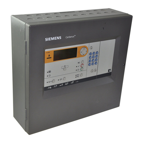
Siemens FIREFINDER-XLS User manual

Siemens

Siemens FIREFINDER-XLS User manual

Siemens MJ-4A User manual

Siemens

Siemens MJ-4A User manual

Siemens SINAMICS Intelligent Operator Panel User manual

Siemens

Siemens SINAMICS Intelligent Operator Panel User manual

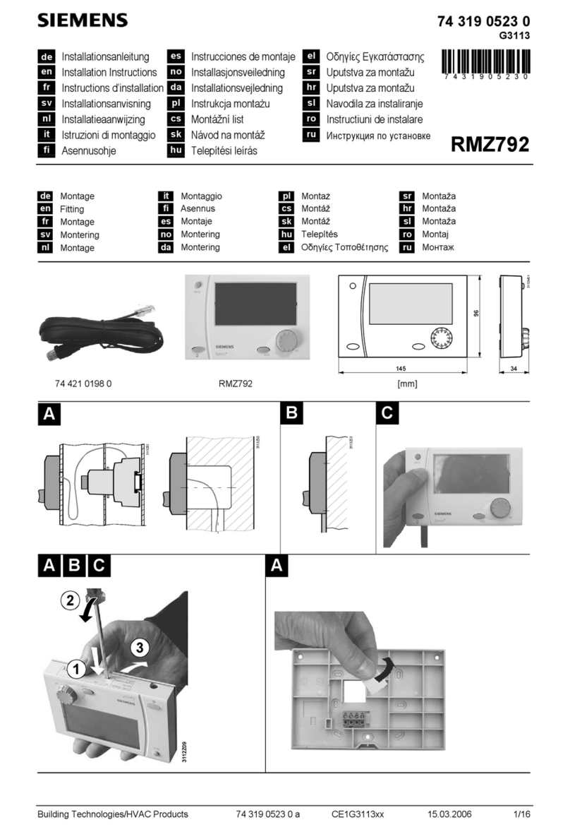
Siemens Synco RMZ792 User manual

Siemens

Siemens Synco RMZ792 User manual

Siemens simatic hmi op27 Technical Document

Siemens

Siemens simatic hmi op27 Technical Document

Siemens FC123-ZA User manual

Siemens

Siemens FC123-ZA User manual

Siemens FC361-ZZ User manual

Siemens

Siemens FC361-ZZ User manual

Siemens FC123-ZA User manual

Siemens

Siemens FC123-ZA User manual

Siemens QAX903 User manual

Siemens

Siemens QAX903 User manual

Siemens SIGMASYS C User manual

Siemens

Siemens SIGMASYS C User manual

Siemens FC7xx User manual

Siemens

Siemens FC7xx User manual

Siemens SIMATIC Mobile Panel 277 IWLAN User guide

Siemens

Siemens SIMATIC Mobile Panel 277 IWLAN User guide

Siemens SINAMICS BOP-2 User manual

Siemens

Siemens SINAMICS BOP-2 User manual

Siemens SINUMERIK MCP-S Series Technical Document

Siemens

Siemens SINUMERIK MCP-S Series Technical Document

Siemens Class 87 User manual

Siemens

Siemens Class 87 User manual

Siemens FC121-ZA User manual

Siemens

Siemens FC121-ZA User manual

Siemens SINAMICS IOP User manual

Siemens

Siemens SINAMICS IOP User manual

Siemens FC901 User manual

Siemens

Siemens FC901 User manual

Siemens RWB1007 User manual

Siemens

Siemens RWB1007 User manual

Siemens GENESIS II User manual

Siemens

Siemens GENESIS II User manual

Siemens SINAMICS IOP-2 User manual

Siemens

Siemens SINAMICS IOP-2 User manual

Popular Control Panel manuals by other brands

Beninca MATRIX manual

Beninca

Beninca MATRIX manual

Tekmar Mixing Setpoint Control 153 Data brochure

Tekmar

Tekmar Mixing Setpoint Control 153 Data brochure

DSC LCD 5500 manual

DSC

DSC LCD 5500 manual

ADT Unimode 9600 Installation and operating instruction

ADT

ADT Unimode 9600 Installation and operating instruction

Pima Hunter-Pro 832 Programming steps

Pima

Pima Hunter-Pro 832 Programming steps

NAPCO MFA6000 Operating & installation instructions

NAPCO

NAPCO MFA6000 Operating & installation instructions

Honeywell Fire-lite ECC-LOC Product Installation

Honeywell

Honeywell Fire-lite ECC-LOC Product Installation

Vallox Exxeo manual

Vallox

Vallox Exxeo manual

Rosslare AC-020 Hardware installation and user's guide

Rosslare

Rosslare AC-020 Hardware installation and user's guide

JCM GAMMA VERSUS Series manual

JCM

JCM GAMMA VERSUS Series manual

Chromalox IntelliTrace ITAS-EXT installation manual

Chromalox

Chromalox IntelliTrace ITAS-EXT installation manual

Zennio InZennio Z38i product manual

Zennio

Zennio InZennio Z38i product manual

BFT LEO-D-MA Installation and user manual

BFT

BFT LEO-D-MA Installation and user manual

tau K127MA installation guide

tau

tau K127MA installation guide

BFT SIRIO CBA 230 INV installation manual

BFT

BFT SIRIO CBA 230 INV installation manual

Fike GB2426367 user guide

Fike

Fike GB2426367 user guide

DSPPA PC1012M owner's manual

DSPPA

DSPPA PC1012M owner's manual

American Standard Gold 824 user guide

American Standard

American Standard Gold 824 user guide

manuals.online logo
manuals.online logoBrands
  • About & Mission
  • Contact us
  • Privacy Policy
  • Terms and Conditions

Copyright 2025 Manuals.Online. All Rights Reserved.