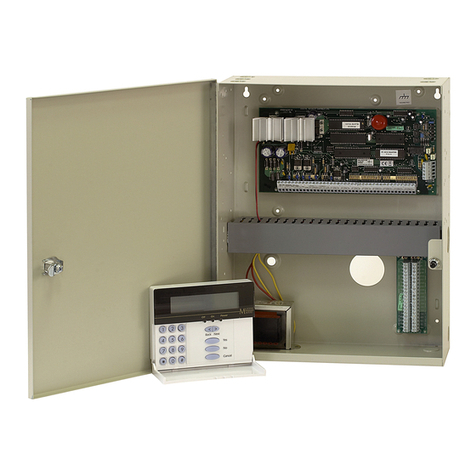
DSC PC1580BABT User manual

1
1.1 Specifications
Control Panel Specifications
Flexible Zone Configuration:
• Six fully programmable zones
• Seven Access Codes: five User, one Master and a
second Master code
• Normally Closed, Single EOL, Double EOL
• 23 Zone Types, 6 Programmable Zone Options
Audible Alarm Output:
• Supervised Bell Output (current limited at 3 amps), 12 VDC
• Steady or Pulsed Output
EEPROM Memory: Does not lose programming or
system status on complete AC and Battery failure
Programmable Outputs:
• Two Programmable Voltage Outputs, 20
programmable options
- One High Current (300 mA) PGM output on main
panel
- One Low Current (50 mA) PGM output on main
panel
Powerful 1.5 Amp Regulated Power Supply:
• 550 mA Auxiliary Supply, 12 VDC
• Positive Temperature Coefficient (PTC) components
replace fuses
• Supervision for loss of AC Power, Low Battery
• Internal Clock Locked to AC Power Frequency
Power Requirements:
• Transformer = 16.5 VAC, 40VA
• Battery = 12 volt 4 Ah minimum rechargeable sealed
lead acid
Remote Keypad Specifications:
• Three Different Keypads Available:
- PC5506T 6 Zone LED Keypad
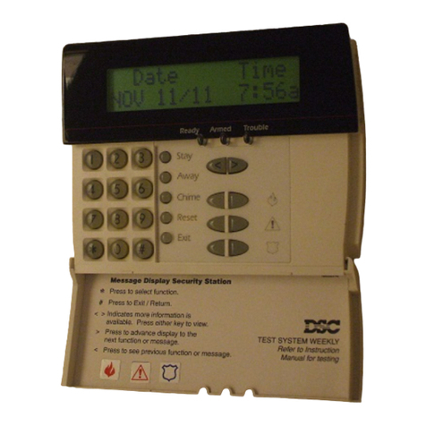
- LCD5500T Alphanumeric Keypad
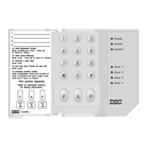
- PC1575RK 6 Zone LED Keypad
• The PC5506T and LCD5500T keypads have 5 Fully
Programmable Function Keys and Tampers
• Connect up to 8 Keypads
• Four Wire (Quad) Connection to KEYBUS
• Built in Piezoelectric Buzzer
Digital Communicator Specifications:
• Supports Major Formats including SIA, Scantronics 4-8-1
Slot and Contact ID
• Event Initiated Personal Paging
• Three Programmable Phone Numbers
• Two Account numbers
• DTMF and Pulse Dialing
• DPDT Line Seizure
• Anti-jam Feature
• Split Reporting of Selected Transmissions to Each
Telephone Number
SystemIntroduction
SECTION1
System Supervision Features
The PC1580 continuously monitors a number of possible
trouble conditions including:
• AC Power Failure
• Trouble by Zone
• Tamper by Zone
• Fire Trouble
• Telephone Line Trouble
• Failure to Communicate
• Low Battery Condition
• Bell Output Trouble
• Module Fault (Supervisory or Tamper)
• Loss of Internal Clock
• AUX Power Supply Fault
False Alarm Prevention Features
• Audible Exit Delay
• Audible Exit Fault
• Communication Delay
• Urgency on Entry Delay
• Quick Exit
Additional Features
• Auto Arm at Specified Time
• Keypad Activated Alarm Output and Communicator
Test
• All modules connect to the system via a four wire
KEYBUS up to 1000’/330m from main panel
• Event Buffer can be printed using PC5400 RS232 Serial
Interface module
• Supports the ESCORT 5580 Voice Prompt Module with
Automation/Lighting Control
• An Event Buffer which records the past 100 events with
both the time and date at which they occured
• Uploading and Downloading capability
• Local Downloading capability with the use of the
PC-LINK Adaptor
• Time compensation feature
1.2 Additional Devices
1.2.1 Keypads
A maximum of eight keypads can be connected to the
control panel and can be any combination of the following
listed.
• PC5506T 6 zone LED keypad with function keys and
tamper
• LCD5500T LCD keypad with function keys and tamper
• PC1575RK 6 zone LED keypad
1.2.2 ESCORT5580 Module
Therearemanybenefitsto adding theESCORT5580module
to a security system. The ESCORT5580 module will turn any
touch tone phone in the world into a fully functional keypad.
Imagine the security a customer would feel if they had the
ability to arm, disarm and check status of their alarm system
while at the office or on vacation.

SYSTEMVINTRODUCTION
2
All touch tone phones in the home also become system
keypads. For example, atbedtime, the phone beside the bed
can be used to arm the system. The addition of the
ESCORT5580 may reduce the cost of the overall installation,
eliminating the need for additionalkeypads andthe labour of
running wires.
The ESCORT5580 will also act
as a tutor for the system. By
using clear, easy to understand
sentences, the voice module
helps guide the user through
functions they may otherwise
find difficult to navigate. Programmable zone labels (up to
6 words each from our library of over 240 words) makes the
system even easier to use.
The module also has a built-in power line control interface
and can control up to 32 power line control devices for
lighting and temperature control, giving you the power to
add home automation in a very cost effective manner.
Devices can be activated individually, as a group, by
schedule or can be activated when an event occurs on the
system, such as an alarm.
These are just a few of the applications available with the
addition of the ESCORT5580 module. For more information,
please refer to the ESCORT5580 Installation Manual.
1.2.3 PC5400 Printer Module
This module will give you the
added advantage for the
commercial customers who
like the idea of a permanent
record of openings and
closing but are put off by the
additional monthly
monitoring charge. In addition, as reports are generated in
real-time, the customer will not have to wait for a monthly
report form the monitoring station.
The PC5400 Printer Module will allow the panel to print out
all events that occur on the system to any serial printer. The
printoutwillcontainthetime,dateandtheeventthatoccurred
(see Section – 5.25 “On-site Printer”).
1.2.4 Downlook Video Transmission Module
TheDownlookStill-FrameVideoTransmissionModule(DLM-
1/DLM-4)istheidealsolutionforallbusinessandresidential
environments which require visual surveillance but where
the presence of on-site security personnel is impossible,
undesirable or unaffordable.
Downlook is the smart and inexpensive way to add visual
backup to your regular remote alarm signalling system,
meeting your demand for tighter security on a tight budget.
The added visual protection will reduce the incidence of
false alarms as well as surveillance costs, thus improving
the overall security protection.
For more information regarding the Downlook Video
Transmission Module, please consult the DLM-1/DLM-4
Installation Manuals.
1.2.5 Cabinets
Several different cabinets are available for the PC1580
modules. They are as follows:
PC5003C Cabinet
Control cabinet for the PC1580 main panel. Dimensions
288mmx298mmx78mm/11.3”x11.7”x3”approximately.
PC5004C Cabinet
Cabinet to house the Escort5580 Module or the PC5400
Printer Module. Dimensions 229mm x 178mm x 65mm / 9”
x 7” x 2.6” approximately.
1.3 Out of the Box
Please verify that each of the following components is
included in your system:
• one PC1580 control cabinet
• one PC1580 control circuit board
• one keypad (LED keypad or LCD keypad)
• one Installation Manual including Programming
Worksheets
• one Instruction Manual for the end user
• one hardware pack consisting of:
-four plastic circuit board standoffs
-twelve 5600Ω(5.6K) resistors
-one 2200Ω(2.2K) resistors
-one 1000Ω(1K) resistor
-EGND Assembly
-one cabinet door plug
• 220V to16.5V AC transformer with fuseblock
• twoyellowsafetyhazardwarninglabelstobeappliedbythe
installer
Enclosed 240V AC Warning Labels
The Health & Safety (Signs and Signals) Regulations state
that warning signs must be displayed to warn people to be
careful to take precautions where a hazard exits.
ThesesignsalsocomplytotheElectricityatWorkRegulation
1989 and BS5378.
TheRegulationsforElectricalInstallation(16Edition)Section
514-10 Warning Notice Voltage.
EveryItemofEquipmentorenclosurewithinwhichavoltage
exceeding250Voltsexists,andwherethepresenceofsuch
a voltage would not normally be expected, shall be so
arranged that before access is gained to a live part, a
warning of the maximum voltage present is clearly visible.
Itisrecommendedthatoneoftheenclosedwarningstickers
beattachedtothe externalareaofthecontrolpanelhousing
to give indication of voltage before access is gained to the
transformer area. The second enclosed warning sticker
should be placed on the front plate of the unswitched fuse
unit to give indication of mains connection within.
DSC accepts no responsibility for the non use of these
warning labels and can confirm that it is the responsibility of
the installation engineers to attach them to the required
devices during the installation process. The warning labels
are enclosed to be used in accordance with the Health and
Safety regulations and also the electricity at work act 1989.

3
GettingStarted
SECTION2
The following Sections provide a thorough description of how to
wire and configure devices and zones.
2.1 Installation Steps
The following steps are provided to assist you with installing
the panel. We suggest that you read this section in its entirity
beforeyoubegin.Onceyouhaveanoverallunderstandingof
the installation process, carefully work through each step.
Workinginthismannerwillreducethenumberofproblemsas
wellastheamountoftimerequiredforacompleteinstallation.
Step 1 Create a Layout
Drawaroughsketchofthebuildingtogetanideaofwhere
all alarm detection devices, keypads and other modules
are to be located.
Step 2 Mounting the Panel
Locate the panel in a dry area close to an unswitched AC
power source and the incoming telephone line. Before
attaching the cabinet to the wall, be sure to press the four
circuitboardmountingstudsintothecabinetfromtheback.
After you have attached the cabinet to the wall, stick the
provided DSC logo sticker on the front of the cabinet.
You must complete all wiring before applying AC or
connecting the battery to the panel.
Step 3 Wiring the KEYBUS (Section 2.3)
Wire the KEYBUS to each of the modules following the
guidelines provided in Section 2.3 of this manual.
Step 4 Zone Wiring (Section 2.8)
You must power down the control panel to complete all
zone wiring. Please refer to Section 2.8 when connecting
zones using normally closed loops, single EOL resistors,
double EOL resistors, Fire zones and Keyswitch Arming
zones.
Step 5 Complete Wiring (Section 2.2)
Complete all other wiring including bells or sirens, phone
line connections, and ground connections following the
guidelines provided in Section 2.2 (“Terminal
Descriptions”).
Step 6 Power up the Control
Once all zone and KEYBUS wiring is complete, power up
the control panel.
The panel will not power up on the battery connec-
tion alone.
Step 7 Keypad Assignment (Section 2.5)
Inorderforkeypadstobeproperlysupervised,eachmust
beassignedtoadifferentslot.Pleasefollowtheguidelines
provided in Section 2.5 when assigning keypads.
Step 8 Supervision (Section 2.6)
The supervision of every module by the panel is
automatically enabled upon power up. Please verify that
all modules appear on the system according to the
instructions in Section 2.6.
Step 9 Programming the System (Sections 4 and 5)
Section 4 explains how to program the panel. Section 5
contains a complete description of the various
programmable features, which options are available and
how they function. The Programming Worksheets (pages
25-33) should be filled out completely before attempting
to program the system.
Step 10 Testing the System
The panel must be thoroughly tested to ensure that all
features and functions are operating as programmed.
2.2 Terminal Descriptions
AC Terminals – AC (50Hz)
The panel requires a 16.5 volt, 40 VA transformer. Connect
the transformer to an unswitched AC source and connect
the transformer to these terminals.
Do not connect the transformer until all other wiring
is complete.
The panel must have a power line frequency of
50Hz.
Battery Connection
A12V4Ahrechargable gel-cellbatteryisused as abackup
source of power in the event of an AC power failure. The
battery also provides additional current when the panel’s
demands exceed the power output of the transformer, such
as when the panel is in alarm.
Do not connect the battery until all other wiring is
complete.
ConnecttheREDbatteryleadtothepositivebatteryterminal;
connect the BLACK lead to negative.
Auxiliary Power Terminals – AUX+ and AUX-
These terminals provide up to 550 mA of additional current
at 12 VDC for devices requiring power. Connect the positive
sideofanydevicerequiringpowertotheAUX+terminal,the
negativesidetoAUX-(ground).TheAUXoutputisprotected.
This means that if too much current is drawn from these
terminals (such as a wiring short), the panel will temporarily
shut off the output until the problem is corrected.
Bell Output Terminals – BELL+ and BELL- (Section 3.4)
Theseterminals provideup to 700mA ofcontinuous current
at12VDCforpoweringbells,sirens,strobesorotherwarning-
type equipment. Connect the positive side of any alarm
warning device to BELL+, the negative side to BELL–.
Please note that the Bell output is protected: if too much
current is drawn from these terminals (such as a wiring
short), the Bell fuse will open. Three Amps can be drawn for
short periods only.
The Bell output is supervised. If no alarm warning devices
are in use, connect a 1000 ohm resistor across BELL+ and
BELL– to prevent the panel from displaying a trouble
condition. For more information, please refer to Section 3.4
(“[✱] [2] Trouble Display”).
The bell is programmed by default to terminate after four
minutes. The Bell Cutoff time can be adjusted in
programming section [02] (“System Times”).
KEYBUSTerminals– AUX+,AUX-,YEL,GRN(Section2.3)
The KEYBUS is used by the panel to communicate with
modules and vice versa. Each module has four KEYBUS
terminals that must be connected to the four KEYBUS
terminals on the panel. For more information, see Section
2.3 (“KEYBUS Operation and Wiring”).

G E T T I N G S T A R T E D
4
Programmable Outputs – PGM1 and PGM2
Each PGM output is designed so
thatwhenactivatedbythepanel,the
terminal will switch to ground.
PGM2cansinkupto50mAofcurrent
to activate LEDs or a small buzzer.
Connectthe positiveside ofthe LED
orbuzzertoAUX+,the negativeside
to PGM2. If more than 50 mA of
currentare required,a relaymust be
used. Please study PGM wiring in
the accompanying diagram.
PGM1 is a high current output which
operates similar to PGM2. PGM1 is
used for high current output (300mA).
Zone Input Terminals – Z1 to Z6
Each detection device must be connected to a zone on the
control panel. We suggest that one detection device be
connected to each zone; wiring multiple detection devices
to a single zone, however, is possible. For zone wiring
specifics, please see Section 2.8 (“Zone Wiring”).
Telephone Connection Terminals – TIP, RING, T-1, R-1
If a telephone line is
required for central
stationcommunicationor
downloading,connectan
RJ-31Xtelephonejackin
the following manner:
• TIP - Green Wire incoming line from
• RING - Red Wire telephone company
• R-1 - Grey Wire outgoing line to
• T-1 - Brown Wire house telephone(s)
Please ensure that all plugs and jacks meet the
correct dimension, tolerance and metallic plating
requirements.
For proper operation, no other telephone equipment
should be connected between the control panel and
the telephone company facilities.
Do not connect the alarm panel communicator to
telephone lines intended for use with a fax machine.
These lines may incorporate a voice filter which
disconnects the line if anything other than fax
signals are detected, resulting in incomplete
transmissions.
2.3 KEYBUS Operation and Wiring
The KEYBUS is used by the panel to communicate with all
connected modules and vice versa. The red (AUX+) and
black (AUX-) terminals are used to provide power, while the
yellow (YEL) and green (GRN) terminals are clock and data
respectively.
The four KEYBUS terminals of the panel must be
connected to the four KEYBUS terminals or wires of
all modules.
The following restrictions apply to KEYBUS wiring:
• KEYBUS should be run in minimum 22 gauge quad
(0.5mm); two pair twist is preferred.
• The modules should be home run to the panel but can
be connected in series or T-tapped .
• Any module can be connected anywhere along the
KEYBUS. You do not need to run a separate KEYBUS
wire for keypads, etc.
• No module can be more than 1,000'/330m (in wire
length) from the panel.
• Shielded wire should not be used unless wires are run
in an area that presents excessive RF noise or other
such interference.
Example of KEYBUS Wiring
NOTE:
Module (A) is correctly
wired within 1,000'/330m
of wire from the panel.
Module (B) is correctly
wired within 1,000'/330m
of wire from the panel.
Module (C) is NOT wired
correctly as it is further
than1,000'/330mfromthe
panel, in wire distance.
2.4 Current Ratings – Modules and
Accessories
In order for the PC1580 system to operate properly, the
power output capabilities of the main control and the
expansion devices must not be exceeded. Use the data
presented below to ensure that no part of the system is
overloaded and cannot function properly.
PC1580 (12 VDC)
VAUX: 550 mA. Includes one keypad. Subtract for each
additional keypad, expansion module and acces-
sory connected to VAUX or KEYBUS.
BELL: 700 mA. Continuous Rating. 3.0 A. Short Term.
Available only with stand-by battery connected.
PC1580 Device Ratings (@ 12 VDC)
• LCD5500T Keypad: 50 mA
• PC5400 Serial Module: 65 mA
• PC5506T Keypad: 45 mA
• PC1575RK Keypad: 50 mA
• DLM-4: 160 mA standing / 180 mA transmitter
• Escort: 65 mA standing / 130 mA on-line
Other Devices
Please read the manufacturer’s literature carefully to
determine the maximum current requirements for each
device—duringactivationoralarm—andincludethe proper
values for loading calculations. Connected devices must
not exceed system capabilities during any possible
operational mode.
2.5 Keypad Assignment
Thereareeightavailableslotsforkeypads.LEDkeypadsby
default are always assigned to slot 1; the LCD5500T is
alwaysassignedtoslot8.WhereasthePC1575LEDkeypad
must always be assigned to slot 1, the PC5506T and
BLK
RED
DSC
RM-1
WHT
YEL
GRN
COM NC NO
+AUX PGM1
(ANY OUTPUT
TERMINAL)
RING TIP R-1 T-1 EGND
GRY
BRN
GRN
RED
TO
TELEPHONE
COMPANY
TO
PREMISE
TELEPHONE
RJ31X
TELEPHONE
PLUG

G E T T I N G S T A R T E D
5
LCD5500Tkeypadscaneachbeassignedtoadifferentslot
(1to 8). Keypad enrollment isrequired since the panel must
know which slots are occupied in order to generate a fault
when a supervisory is not present.
How to Assign Keypads
Each keypad must be assigned one at a time. After
assigning all keypads, a supervisory reset should
be performed.
To assign a keypad to a slot, enter the following:
1. Enter Installer’s Programming.
2. Press [00] for Keypad Programming.
3. Press [0] for Slot Assignment.
4. Enter a two digit number (11-18) to specify which
supervisory slot the keypad will occupy.
Press the [#] key twice to exit programming. Continue this
procedureateachkeypaduntiltheyhaveallbeenassigned
to the correct slot.
When using more than one LCD keypad, be sure
that only one is assigned to slot number 8.
2.6 Supervision
By default, all modules are supervised upon installation.
Supervision is enabled at all times so that the panel can
indicate a trouble if a module is removed from the system.
A connected module which does not show as being present
will appear as a trouble condition and the Trouble light on the
keypadwill turn ON. This conditionmay bedue to one or more
of the following reasons:
• the module is not connected to the KEYBUS
• there is a KEYBUS wiring problem
• the module is more than 1,000'/330m from the panel
• the module does not have enough power
Formoreinformationregardingmodulesupervisiontroubles,
please refer to Section 3.4 (“[✱] [2] Trouble Conditions”).
Modules will not be automatically supervised if
connected while in installers mode.
2.7 Removing Modules
Thepanelmustbeinstructedtonolonger supervise a module
being removed from the system. To remove the module,
disconnect it from the KEYBUS and reset the supervision
field by entering [92] in the installer’s programming.The
panel will be reset to recognize and supervise all existing
modules on the system.
2.8 Zone Wiring
For a complete description of the operation of all zone types,
please refer to Section 5.2 (“Zone Definitions”).
There are several different ways in which zones may be
wired, depending on which programming options have
been selected. Please refer to the following diagrams to
study each type of individually supervised zone wiring.
Any zone defined as Fire will automatically require a
single End of Line (EOL) resistor regardless of which
type of zone wiring supervision is selected. (See Section
5.2 “Zone Definitions.”) Reconfiguring the zone supervi-
sion from a non-default setting—from DEOL to EOL or
from NC to DEOL—may disable zones 1-6 while open or
in trouble. To prevent this situation, the system should be
powered down completely and powered up again.
2.8.1 Normally Closed (NC) Loops
2 NORMALLY CLOSED
CONTACTSWITH
NO END OF LINE
RESISTOR
ANY Z
TERMINAL ANY COM
TERMINAL
NORMALLY CLOSED
CONTACTWITH
NO END OF LINE
RESISTOR
ANY Z
TERMINAL ANY COM
TERMINAL
This option should only be selected if Normally Closed
(NC) detection devices or contacts are being used.
2.8.2 Single End Of Line (EOL) Resistors (5600W)
NORMALLY
CLOSED
CONTACT WITH
END OF LINE
RESISTOR
ANY Z
TERMINAL ANY COM
TERMINAL
NORMALLY OPEN
CONTACTS WITH
END OF LINE
RESISTOR
ANY Z
TERMINAL ANY COM
TERMINAL
ANY Z
TERMINAL ANY COM
TERMINAL
2 NORMALLY OPEN
CONTACTS AND
2 NORMALLY CLOSED
CONTACTS WITH
END OF LINE
RESISTOR
1 NORMALLY OPEN
CONTACT AND
1 NORMALLY CLOSED
CONTACT WITH
END OF LINE
RESISTOR
ANY Z
TERMINAL ANY COM
TERMINAL
This option should be selected if either Normally
Closed (NC) or Normally Open (NO) detection
devices or contacts are being used.
2.8.3 Double End of Line (DEOL) Resistors
Double End of Line resistors allow the panel to determine if
the zone is in alarm, tampered or faulted.
ANY Z
TERMINAL ANY COM
TERMINAL
ALARM
CONTACT
DOUBLE EOL CIRCUIT
1 NORMALLY CLOSED
CONTACT WITH
5600 END OF LINE
RESISTORS
Ω
This option can only be selected if Normally Closed
(NC) detection devices or contacts are being used
(ie: Do not use DEOL resistors for Fire zones.
Only one NC contact can be connected to each
zone. Multiple detection devices or contacts on a
single loop is not allowed.
The following chart shows zone status under certain
conditions:
• Loop Resistance ................................ Loop Status
• 0Ω(shorted wire, loop shorted) ....... Fault
• 5600Ω(contact closed) .................... Secure
• Infinite (broken wire, loop open)....... Tamper
• 11200Ω(contact open) ..................... Violated

G E T T I N G S T A R T E D
6
2.8.4 Fire Zone Wiring — Four-Wire Smoke Detectors
All fire zones must be wired according to the following
diagram:
4-WIRE SMOKE DETECTOR CONNECTION WITH RESET
ALARM
CONTACT
IN
IN
OUT
OUT
ALARM
CONTACT
IN
IN
OUT
OUT
BLK WHT
RED GRN
POWER
SUPERVISORY
RELAY
(DSC RM-1)
5600
END OF LINE RESISTOR
(EOLR-2)
Ω
●
MINIMUM 18 AWG WIRING IS REQUIR
FOR RESIDENTIAL FIRE ALARM SYST
TO ZONE "Z"
TERMINAL
PROGRAMMED
FOR "FIRE"
TO ANY "COM"
TERMINAL
AUX
+
+ BELL -1 PG M 2
2.8.5 Keyswitch Zone Wiring
If PGM2 has been
programmed for keyswitch
operation (momentary or
maintained), the
keyswitches must be wired
according to this diagram:
NORMALLY CLOSED
CONTACT WITH
5600 ENDOF LINE
RESISTOR
Ω
PGM2 AUX+
2.9 Wiring Gauge Conversion Table
North American Gauges Metric Wire Diameter
(AWG) (mm)
AWG-14 1.62mm
AWG-16 1.29mm
AWG-18 1.02mm
AWG-19 0.91mm
AWG-20 0.81mm
AWG-21 0.72mm
AWG-22 0.64mm
AWG-24 0.50mm

7
KeypadCommands
SECTION3
The PC1580 alarm panel can be accessed, controlled and
completely programmed via any keypad on the system. The
LED keypad uses function and zone indicator lights to repre-
sent alarm functions and status. The LCD keypad provides a
written description on the liquid crystal display and uses
function indicator lights to communicate alarm status to the
user.
The following sections describe how to arm and disarm the
system from each type of keypad, and how to perform other
keypad functions.
3.1 Arming and Disarming
The system cannot be armed unless the Ready light is ON.
Inorder forthe system to be inthe Readystate, allprotected
doors and windows must be secured and all movement in
areas covered by motion detectors must cease. When the
Ready light is ON, enter any valid access code. As each
digit is pressed, the keypad will beep. If the correct code is
enteredwhen the systemis not inthe Ready state,the panel
will sound six quick beeps followed by a long two-second
beep to indicate that the system is not secured.
Ifan incorrect code is entered,the keypadwill emit asteady
twosecondbeep to indicatetheinvalid access code.When
the correct code is entered and the system is Ready, the
panel will emit six short beeps and the Armed light will turn
ON. Exit the premises through the designated entry/exit
door. For other methods of arming, please refer to section
3.4 (“[✱] [0] Quick Exit” and “[✱] [9] Arming Without Entry
Delay”) and section 3.5 (“Function Keys”).
Inan attemptto preventfalse alarms,the Audible Exit Fault is
designed to notify the user of an improper exit when they arm
theirsystem.Ifanonforce-armingDelay1orDelay2typezone
isleftopenattheendoftheexitdelay,theentrydelaywillbegin
immediately and the bell or siren will sound a steady alarm for
the entry delay period. At the end of the entry delay period, if
the system has not been disarmed it will go into alarm.
When you enter the premises through a designated entry/
exit door while the system is armed, the keypad will emit a
steady beep to remind you to disarm the system. Enter a
valid access code from any keypad to disarm the system. If
anerrorismade,pressthe[#]keyand enter thecodeagain.
When a correct code is entered, the Armed light will turn
OFF and the keypad will stop beeping. During the last 10
seconds of entry delay, the panel will pulse the keypad
beeper ON and OFF rapidly to warn you that the entry delay
is about to expire.
Ifanalarmoccurredwhilethepanelwasarmed,theMemory
light and the zone indicator lights corresponding to the
zones which went into the alarm will be flashing. Press the
[#] key to return the keypad to the Ready state.
3.2 Auto Bypass – Stay Arming
Stay arming allows the user to arm the system without
leavingthe premises. Allinterior zonescanbe programmed
tobebypassedduringStayarmingsothattheuserdoesnot
have to bypass interior zones manually.
When the system is armed using a valid user code, if any
zones on the system have been programmed as Stay/Away
zones, the Bypass light will turn ON. The panel will then
monitor all zones programmed as Delay 1 and Delay 2
zones,such as designated entry/exit doors.If no delay type
zone is violated by the end of the exit delay, the panel will
bypass all Stay/Away type zones. The Bypass light will
remain ON to inform the user that the interior protection has
been automatically bypassed by the panel. If a delay zone
isviolated duringthe exitdelay, the Stay/Away zones will be
active after the exit delay expires.
TheusercanaddtheStay/Awayzonesbackintothesystem
at any time by entering the [✱][1] keypad command (see
section 3.4 “[✱] [1] Bypassing and Reactivating Stay/Away
Zones”).
Stay arming can also be initiated by pressing and holding
the Stay function key for two seconds on the PC5506T and
LCD5500T keypads, if programmed by the installer. For
moreinformationregardingStayarming,pleaseseesection
3.5 (“Function Keys”).
3.3 Automatic Arming
The system can be programmed to Auto-Arm at a specific
time every day if it is in the disarmed condition.
In order for the Auto-Arm function to work properly, the
correct Time of Day must be programmed. To program the
clock and Auto-Arm times, see Section 3.4 ([✱][6] User
Functions)
When the system’s internal clock matches the Auto-Arm
Time, the panel will check the system status. If armed, the
panel will do nothing until the next day at the Auto-Arm
Time, when it will check the system again. If disarmed, the
panel will sound the buzzer of all keypads for one minute. If
a valid User Code is entered, the Auto-Arming will be
aborted.
If no code is entered, the panel will Auto-Arm. If a zone is
violated,thepanelwilltransmita Partial Closing Reporting
Code–ifprogrammed– toindicatetothecentralstationthat
the system is not secure. If the zone is restored, the panel
will add the zone back into the system (see Section 5.7
“Communicator – Reporting Codes”).
3.4 [✱]Commands
The [✱]key commands provide an easy way for the user to
access basic system programming – such as entering user
codesorbypassing zones.Theuser can alsouse the [✱]key
commandstocheckonthesystem’sstatus,includingviewing
troubleconditionsanddisplayingtheeventbufferontheLCD
keypad.
The [✱]key commands can be performed from both LCD
andLEDkeypads. The LEDkeypaduses the zoneindicator
lights to display command information. The LCD display
provides written information, guiding the user through each
command. The commands in this section are explained as
viewed from an LED keypad. When using an LCD keypad,
use the arrow keys (< >) to scroll through information
provided.Otherwise,thefunctionsremainthesameforboth
keypad types.
[✱][1] Bypassing and Reactivating Stay/
Away Zones
The [✱][1] keypad command can be used to bypass
individual zones. A bypassed zone will not cause an alarm.
The user can bypass zones to gain access to an area while
arming the rest of the system or to override a defective
zone—due to a bad contact or damaged wiring—until
service can be provided.

KEYPADVCOMMANDS
8
If the Code Required for Bypass option is enabled, only
user codes with the Bypass attribute enabled will be able to
bypass zones (see section 5.1 “Programming Security
Codes”).
If the Bypass Status Displayed While Armed is chosen,
the Bypass light will be ON while the system is armed to
indicate any bypassed zones (see section 5.15 “Arming /
Disarming Options”).
Zones can only be bypassed when the system is
disarmed.
To bypass a zone:
1. Enter [✱][1] (and an access code, if required).
2. The keypad will flash the Bypass light and the zone
indicator lights corresponding to any zones already
bypassed will turn ON.
3. Enter the number corresponding to the zone you wish
to bypass. The corresponding zone indicator light will
turn ON.
4. Press [#] to exit the function.
All zones whose indicator lights are ON when the [#]
key is pressed will be bypassed. The Bypass light will
turn ON, indicating that zones are bypassed.
To reactivate a bypassed zone:
1. Enter [✱][1] (and an access code if required).
2. The keypad will flash the Bypass light. The zone
indicator lights corresponding to any zones already
bypassed will turn ON.
3. Enter the number corresponding to the bypassed zone
you wish to reactivate. The corresponding zone
indicator light will turn OFF.
4. Press [#] to exit the function.
All zones whose indicator lights are ON when the [#]
key is pressed will be bypassed. If no zone indicator
lights were ON, the Bypass light will be OFF and no
zones will be bypassed.
When the system is disarmed, all manually-by-
passed zones will be unbypassed.
Reactivate Interior
If the system is armed in the Stay mode,the [✱][1] command
can be used to reactivate the Stay/Away zones.
Reactive Stay/Away cannot be used with an alarm in
memory.
Please ensure all force-armed zones are restored
before reactivating the Stay/Away zones (See
Section 5.3 “Zone Attributes”).
[✱][2] Trouble Display
The panel constantly monitors itself for several different
trouble conditions. If a trouble condition is present, the
Trouble light will be ON and the keypad will beep twice
every 10 seconds. The trouble beep can be silenced by
pressing any key on any keypad.
To view trouble conditions from an LED keypad:
1. Press [✱][2].
2. ThekeypadwillflashtheTroublelight. Thezoneindicator
lights corresponding to the present trouble conditions
will be ON.
When using an LCD keypad, the trouble conditions will be
listed on the display; the user must simply use the arrow (< >)
keys to scroll through the list of present trouble conditions.
The various troubles are described below:
Trouble [1] – Service Required
If zone indicator light [1] is ON, a “service required” trouble
is present. Press [1] to determine the specific trouble. The
following is a list of “service required” trouble conditions:
• Light [1] – Low Battery
The main panel backup battery is low. The trouble will
be generated if the battery drops below 11.5 volts
under load and will be restored when the battery
charges to over 12.5 volts.
• Light [2] – Bell Circuit Trouble
The panel will indicate this trouble if the Bell fuse is
blown or if the panel senses an open condition on the
bell circuit (see Section 5.12 “Siren Supervision”).
• Light [3] – General System Trouble
This trouble will be present if the printer connected to
the PC5400 Printer module has a fault and is off-line, or
if the ESCORT module does not detect the Power Line
Interface Module.
• Light [4] – General System Tamper
This trouble will be indicated if any peripheral module
tamper is detected.
• Light [5] – General System Supervisory
This trouble will be indicated if the panel loses
communication with any module connected to the
KEYBUS (see Section 2.6 “Supervision”). The event
buffer will log a detailed description of the event.
Trouble [2] – AC Failure
This trouble indicates that AC power is no longer being
supplied to the control unit. The reporting codes in sections
[43] and [44] can be programmed to communicate a power
failuretothemonitoringstation.Toavoidreporting shortpower
failures to the monitoring station, an AC Failure
Communication Delay from 000-255 minutes can be
programmed in section [62].
Trouble [3] – Communication Troubles
Thereare two typesof telephone linetrouble conditions. Press
[3] to display which type of trouble is present:
• [1] – Telephone Line Monitoring Trouble (TLM)
The telephone connection to the control unit is monitored
every 10 seconds. If the voltage drops below one to three
volts for the number of consecutive checks programmed
in section [62], a telephone line trouble is generated.
• [2] – Failure to Communicate (FTC)
This trouble will be generated if the communicator fails
to communicate with any of the programmed telephone
numbers. If a later attempt is successful, the FTC
reporting code(s) programmed in section [45] will be
transmitted along with the unreported events from an
earlier unsuccessful communication.

KEYPADVCOMMANDS
9
Trouble [4] – Zone Fault (including Fire Zone)
This trouble will be generated if any zone on the system is
experiencingtrouble,meaningthatazonecouldnotprovide
an alarm to the panel if required to do so. When a zone fault
trouble condition occurs, the keypad(s) on the system will
start to beep.
Press [4] while in Trouble mode to view the affected zones.
A Fire zone trouble will be generated and displayed
in the armed state. A Fire zone trouble will also
restart the trouble beeps from all keypads.
Trouble [5] – Zone Tamper
This trouble is only generated by zones configured for
Double End Of Line Resistor Supervision when a tamper
condition is present. When a tamper condition occurs, the
keypad(s) will start to beep. Press [5] while in the Trouble
mode to view the affected zones.
Trouble [6] – Loss of System Time
Thistrouble occurs whenthe controlunitis poweredup and
theinternalclockhasnotbeenset.SettingthetimewithUser
Function [✱][6][Master Code][1] will clear this trouble.
[✱][3] Alarm Memory
The‘Memory’lightwillbeonifanyalarmoccurredduringthe
last armed period or – in the case of 24 hour zones – if an
alarm occurred while the panel was disarmed.
To view alarm memory:
Press [✱][3].The keypad willflash the Memorylight and the
zone indicator lights corresponding to the alarm or tamper
conditions which occurred during or since the last armed
period. To clear the Memory light, arm and disarm the
system.
[✱][4] Door Chime On/Off
The door chime feature is used to sound a tone from the
keypad whenever a zone programmed as a chime zone is
activated (see Section 5.3 – “Zone Attributes”). If the door
chime feature is enabled, the keypad will emit five short
beeps whenever a chime zone is activated. Designated
entry/exit doors are often defined as chime zones; when the
featureisenabled,the keypadswillsoundwhenanentry/exit
door is opened.
To turn Door Chime ON or OFF:
1. Press [✱][4].
2. The keypad will emit three short beeps if the Door
Chime feature is enabled and one long beep when
disabled.
Thefunctioncanalsobepeformedbypressing and holding
the Chime function key for two seconds on any PC5506T or
LCD5500T keypad.
[✱][5] Programming Access Codes
There are 6 access codes available to the user. They are as
follows:
Access code (1).............................. One Master Code
Access codes (2) to (6).................. Five User Codes
All access codes have the ability to arm or disarm the
system and can activate the PGM Outputs using the [✱][7]
[1] [Access Code] and [✱][7] [2] commands.
Master Code – Access Code (1)
By default, the Master Code is enabled to perform any
keypadfunction.Thiscodecan be usedtoprogramallUser
Codes. If the Master Code Not Changeable option is
enabled, the Master Code can only be changed by the
Installer.
User Codes – Access Codes (2) to (6)
User codes can arm and disarm the system. By selecting
the No Code Required for Bypassing option, each user
can also have the ability to bypass zones without entering
an access code.
Duress Code – Access Code (6)
If the Sixth Code is Duress Code option is enabled, the
sixth code can be programmed by the user as a Duress
Code which will send a Duress reporting code to the central
station when entered.
Formoreinformationregardingaccesscodeoptions,please
see Section 5.1 – “Programming Security Codes.”
How to program User Codes:
1. Enter [✱][5] [Master Code]. The keypad will flash the
Programlight.The zone indicatorlightscorrespondingto
access codes already programmed will turn ON.
2. Enter the number corresponding to the code you wish to
program. The corresponding zone light will flash.
3. Enter a 4 digit code. The zone light will turn ON.
4. Continue from step 2 until all codes are programmed.
Once the process is complete, press the [#] key to return
to the Ready state.
Do not press [✱] or [#] when programming the 4 digit
code.
How to erase an Access Code:
Enter [✱][5] [Master Code], select the code to be erased
and press [✱].
[✱][6] User Functions
This keypad command can be used to program several
different functions. The programmable items are listed and
described below.
To program User Functions:
1.Press [✱][6] [Master Code]. The Program light will
flash.
2.Press the number [0] to [9] for the item to be
programmed.
• [1] – Time and Date
The time and date must be accurate for the Auto-Arm
or Test Transmission functions to work properly and for
the event buffer to time and date stamp all events.
- Enter the time (hour and minute) using military format
[HH MM] from 00:00 to 23:59.
- Enter the date by month, day and year [MM DD YY].
• [2] – Auto-Arm Enable/Disable
Auto-Arming will not work unless it is enabled for the
system. To enable or disable auto-arming, press [2]. The
keypad will emit three short beeps if the Auto-Arm feature
is enabled and one long beep when disabled. For more
information, see Section 3.3 – “Auto-Arming”.

KEYPADVCOMMANDS
10
• [3] – Auto-Arm Time
The system can be programmed to Auto-Arm at a
certain time. When programming the auto-arming time,
enter the time (hour and minute) using military format
[HH MM]. For more information, see Section 3.3 –
“Auto-Arming”.
• [4] – System Test
When [4] is pressed the panel will test the bell output,
keypad lights and the communicator for two seconds.
The panel will also send a System Test Reporting
code, if programmed (see Section 5.7 – “Communica-
tor – Reporting Codes”).
• [5] – Enable DLS (Downloading)
When [5] is pressed, the panel will enable the down-
loading option for one hour. During this time the panel
will answer incoming downloading calls (see Section
5.9 “Downloading”).
• [6] – User Initiated Call-Up
When [6] is pressed, the panel will initiate call-out to
the downloading computer.
• [7] – Last Code to Disarm and Arm
Pressing [7] will display the last code to disarm the
system. Then, pressing [9] will display the last code to
arm the system.
• [0] – Walk Test Enable / Disable
The Installer Walk Test can be used to verify that each
zone of the panel is functioning properly. Any zone
violated during a walk test will cause the panel to
activate the Bell Output for two seconds, log the event
to the Event Buffer and communicate the alarm to
central station. Do not tamper or fault zones while in
walk test. You can exit walk test with zones open. You
can cancel walk test by arming with all zones restored.
Additional Features using the LCD Keypad
Additionalfeatures,including access totheEvent Buffer, are
available using the LCD keypad. Use the arrow keys (< >) to
scrollthroughthe [✱][6] menuand press the[✱]keytoselect
the following commands:
Viewing the Event Buffer from an LCD Keypad
Select “View Event Buffer” from the [✱] [6] menu. The
keypad will display the event, event number, time and date
along with the zone number and user code, if applicable.
Press [✱] to toggle between this information and the event
itself. Use the arrow keys (<>) to scroll through the events
in the buffer. When you have finished viewing the Event
Buffer, press the [#] key to exit.
Brightness Control
The LCD keypad will allow you to select from 10 different
backlighting levels. Use the arrow keys (< >) to scroll to the
desired backlighting level and press the [#] key to exit.
Contrast Control
The LCD keypad will allow you to select from 10 different
display contrast levels. Use the arrow keys (< >) to scroll to
the desired contrast level and press the [#] key to exit.
Keypad Beeper Control
The LCD keypad will allow you to select from 21 different
keypad beeper tones. Use the arrow keys (< >) to scroll to
the desired keypad beeper level and press the [#] key to
exit. This featured can be accessed on LED keypads by
holding the [✱]key.
[✱][7] OutputFunctions
There are two output functions available to the user: Utility
Output and Sensor Reset.
To activate Utility Output:
Press [✱][7] [1][Access Code].
The panel will activate all PGM Outputs programmed as
utility outputs for five seconds (see Section 5.10 – “PGM
Outputs”).
To activate Sensor Reset:
Press [✱][7] [2].
The panel will activate all PGM Outputs programmed as
Sensor Reset for five seconds.
This function can also be performed by pressing and
holding the Reset function key for two seconds on any
PC5506T or LCD5500T keypad.
[✱][8] Installer’s Programming
Enter [✱][8] followed by the Installer’s Code to enter this
function. Installer’s Programming is outlined in detail in
Sections 4 and 5 of this manual.
[✱][9] Arming Without Entry Delay
When the system is armed with the [✱][9] command, the
panel will cancel the entry delay. Once the exit delay has
expired, Delay 1 and Delay 2 type zones will be instant and
Stay/Awayzoneswillbe bypassed (seeSection5.2–“Zone
Definitions”). A valid access code must be entered after
pressing [✱][9].
[✱][0] Quick Arm
If the Quick Arm option is enabled, the panel can be armed
without a user code by entering [✱][0] (See Section 5.15
“Arming / Disarming Options”).
Quick Arm cannot be used to cancel Auto Arm.
Quick Exit
The Quick Exit function, if enabled, will allow someone to
leaveanarmedpremises through aDelaytypezonewithout
having to disarm and rearm the system (See Section 5.15
“Arming / Disarming Options”).
When [✱][0] is entered, the panel will provide a two minute
windowfortheusertoexitthepremises.Duringthistime,the
panel will ignore only one activation of a Delay zone. When
the Delay zone is secured, the panel will end the two minute
quick exit delay.
IfasecondDelayzoneistrippedorifthezoneisnotrestored
after two minutes, the panel will begin the entry delay.
If the Exit Delay is in progress, performing a Quick
Exit will not extend the Exit Delay.
3.5 Function Keys
The function keys only appear on the PC5506T and
LCD5500T keypads
TherearefivefunctionkeysonthePC5506TandLCD5500T
keypads located to the right of the number pad labelled
Stay, Away, Chime, Reset and Exit. Each of these keys are
programmed by default to perform one of the functions

KEYPADVCOMMANDS
11
described below. A function is activated by pressing and
holding the appropriate key for two seconds.
“Stay” – Stay Arm
Pressing this key will arm the system in the Stay mode,
meaning that all Stay/Away type zones will be automatically
bypassed. Delay type zones will provide entry and exit
delay. The Quick Arm feature must be enabled in order for
this key to function (programming section [10], option [6]).
“Away” – Away Arm
Pressing this key will arm the system in the Away mode. All
Stay/Away type zones and all other non-bypassed zones
will be active at the end of the exit delay. Delay type zones
willprovideentryandexitdelay.TheQuickArmfeaturemust
be enabled in order for this key to function.
“Chime” – Door Chime On / Off
Pressing this key will toggle the Door Chime feature ON or
OFF. One solid beep means that the feature has been
disabled and three short beeps means that it has been
enabled (see Section 3.4 – “[✱] [4] Door Chime”).
“Reset” – Reset Smoke Detectors
Pressing this key will cause the panel to activate for five
seconds all PGM outputs programmed as Sensor Reset.
“Exit” – Activate Quick Exit
Pressingthiskey willcausethe panel toactivatethe Quick Exit
feature (See Section 3.4 – “[✱] [0] Quick Exit”).
3.5.1 Function Key Options
The following is a list of Function Key options available.
Each option is listed according to their programming code,
followedbytheircorresponding[✱]keycommand.Formore
information regarding each function, please refer to the
appropriate segment in section 3.4 (“[✱] Commands”)
[00] – Null Key
The key is not used and will perform no function when
pressed.
[01]-[02]– Not Used
[03] – Stay Arm
Same as described in Function Keys – Section 3.5.
[04] – Away Arm
Same as described in Function Keys – Section 3.5.
[05] – [✱][9] No-Entry Delay Arm
Oncethisfunctionkeyispressedtheusermust enter a valid
user code. The system will arm and remove the entry delay
fromthesystemwhen theexitdelayexpires(seeSection3.4
– “[✱][9] Arming Without Entry Delay”).
[06] – [✱][4] Door Chime On / Off
Same as described in Function Keys – Section 3.5.
[07] – [✱][6] [----] [4] System Test
Thisfunction keyprovides the user with asimple methodfor
testing the system.
[08] – [✱][1] Bypass Mode
Thisfunction keyprovides the user with asimple methodfor
enteringtheBypassMode. Ifausercodeisrequired,itmust
be entered before zone bypassing can be performed.
[09] – [✱][2] Trouble Display
Thisfunction keyprovides the user with asimple methodfor
entering the Trouble Display Mode.
[10] – [✱][3] Alarm Memory
Thisfunction keyprovides the user with asimple methodfor
entering the Alarm Memory Display Mode.
[11] – [✱][5] Programming Access Codes
This function key provides the user with a simple method for
programming user codes. Once this key is pressed, a valid
master code must be entered before the panel will allow
programming to be performed.
[12] – [✱][6] User Functions
This function key provides the user with a simple method for
programming user functions. Once this key is pressed, the
Master code must be entered before the panel will allow user
functions to be performed.
[13] – [✱][7] [1] Utility Output
This function key provides the user with a simple method for
activating a PGM Output programmed as utility output (see
section 5.10 – “PGM outputs”). Once this key is pressed, a
valid user code must be entered.
[14] – [✱][7] [2] Sensor Reset
Same as described in Function Keys – Section 3.5.
[15] – Not Used
[16] – [✱][0] Quick Exit
Same as described in Function Keys – Section 3.5.
[17] – [✱][1] Reactivate Stay/Away Zones
Thisfunction keyprovides the user with asimple methodfor
adding Stay/Away zones back into the system at night-time
(seeSection 3.4 –“[✱][1]BypassingandReactivatingStay/
Away Zones”).

12
G E T T I N G S T A R T E D
How to Program
SECTION4
The following section of the manual describes the Installer’s
Programming function and how to program the various sections.
You must read the following section of the manual
very carefully before you begin programming. We
also recommend filling out the Programming
Worksheets before you program the panel.
For your reference, the corresponding programming sections for
the functions listed are highlighted in text boxes such as this one.
4.1 Installer’s Programming
Installer’s Programmingisusedtoprogramallcommunicator
andpaneloptions.TheInstaller’s Codeis[1575]bydefault
but may be changed to prevent unauthorized access to
programming.
Installer Code ......................................................... Section [03]
From an LED Keypad:
Step 1 Enter [✱] [8] [Installer’s Code].
• The Program light will flash to indicate you are
in programming mode.
• The Armed light will turn ON to indicate that the
panel is waiting for the two digit programming
section number.
Step 2 Enter the two digit Section number corresponding
to the section you wish to program.
• The Armed light will turn OFF.
• The Ready light will turn ON to indicate that the
panel is waiting for the information required to
complete programming the selected section.
Step 3 Enter the information required to complete
section programming (ie: numbers, HEX data, or
ON/OFF options).
If the two digit Section numbered entered is invalid,
or if the module which pertains to the section is not
present, the keypad will sound a two second error
tone.
From an LCD Keypad:
Step 1 From any keypad, enter [✱] [8] [Installer’s
Code]. The Keypad will display ‘Enter
Section’ followed by two dashes.
Step 2 Enter the two digit number corresponding to
the programming section number you wish to
program. The keypad will now display the
information required to complete
programming the selected section.
Step 3 Enter the information required to complete
section programming (ie: numbers, HEX
data, or ON/OFF options).
If you enter information into a section and make a mistake,
pressthe[#]keytoexitthesection.Selectthatsectionagain
and re-enter the information correctly.
4.2 Programming Decimal Data
A set number of programming boxes are allotted for each
section requiring decimal data (e.g.: codes, telephone
numbers). If a digit is entered for each program box, the
panel will automatically exit from the selected programming
section. The Ready light will turn OFF and the Armed light
will turn ON.
Youcanalsopressthe[#]keytoexitaprogrammingsection
without entering data for every box. This is handy if you only
need to change digits in the first few programming boxes.
All other digits in the programming section will remain
unchanged.
4.3 Programming HEX Data
Onoccasion,hexadecimal(HEX)digitsmay berequired.To
program a HEX digit press the [✱] key. The panel will enter
HEX programming and Ready light will begin to flash.
The following are the numbers which should be pressed to
enter the appropriate HEX digit:
1 = A 2 = B 3 = C 4 = D 5 = E 6= F
After the correct HEX digit is entered, the Ready light will
continue to flash. If another HEX digit is required, press the
corresponding number. If a decimal digit is required, press
the [✱]keyagain.TheReadylightwillturn ONandthe panel
will return to regular decimal programming.
Example:
To enter ‘C1’ for a closing by user 1, you would enter
[✱] [3] [✱] , [1]
[✱] to enter Hexadecimal mode (Ready light flashes)
[3] to enter C
[✱] to return to decimal mode (Ready light is solid);
[1] to enter digit 1
If Ready light is flashing, any number you enter will
be programmed as the HEX equivalent.
If you are using a pulse format, a decimal zero [0] does not
transmit. Programming a zero [0] tells the panel not to send
any pulses for that digit. Decimal zero [0] is a filler digit. To
make a zero [0] transmit, it must be programmed as a
Hexadecimal ‘A’.
Example:
For the three digit account number ‘403’, you would enter
[4], [✱] [1] [✱] [3], [0].
[4] to enter the digit 4;
[✱] to enter Hexadecimal mode (Ready light flashes)
[1] to enter A
[✱] to return to decimal mode (Ready light is solid);
[3] to enter the digit 3;
[0] to enter the digit 0 as a filler digit.
4.4 Programming Toggle Option Sections
Some Sections contain several toggle options. The panel
will use zone lights 1 through 6 to indicate if the different
options are enabled or disabled. Press the number
correspondingtotheoptiontoturnitONorOFF.Onceallthe
toggle options have been selected correctly, press the [#]
key to exit the section and save the changes. The Ready

13
HOWVTOVPROGRAM
light will turn OFF and the Armed light will turn ON.
Refer to Section 5 in this manual to determine what each
option represents and whether the light should be ON or
OFF for your application.
4.5 Viewing Programming
LED Keypads
Any programming section can be viewed from an LED
keypad.Whenaprogrammingsectionisentered,thekeypad
will immediately display the first digit of information
programmed in that section.
The keypad displays the information using a binary format,
where Zone Light 1 = 1 Zone Light 2 = 2
Zone Light 3 = 4 Zone Light 4 = 8
Add up the values for the zone lights to determine the
number displayed (for example, no zone lights = 0, all 4
zone lights = 15 HEX ‘F’).
Press any of the Emergency Keys (Fire, Auxiliary or Panic)
to advance to the next digit. When all the digits in a section
have been viewed, the panel will exit the section; the Ready
Light will turn OFF and the Armed light will turn ON, waiting
for the next two digit programming section number to be
entered. Press the [#] key to exit the section
LCD Keypad
When a programming section is entered, the keypad will
immediately display all the information programmed in that
section.
Use the arrow keys (< >) to scroll through the data being
displayed.
Scrollpasttheend of thedatadisplayedor press the[#]key
to exit the section.

14
G E T T I N G S T A R T E D
Program Descriptions
The following section explains the operation of all programmable
featuresandoptionsandprovidesasummaryofallcorresponding
programming locations.
5.1 Programming Security Codes
There are three codes which can be programmed by the
installer in the Installer’s Programming function: the Master
Code, a Second Master Code, and the Installer’s Code. All
otheraccess codes canbe programmedthroughthe [✱][5]
command (see Section 3.4).
The Master Code can also be programmed by the user as
access code (1). If the Master Code Not Changeable
option is enabled, the System Master Code can only be
changed by the Installer.
User codes can arm and disarm the system. By selecting
the No Code Required for Bypassing option, each user
code can also have the ability to bypass zones without
entering the Master Code.
If the Sixth Code is Duress Code option is enabled, the
sixth code can be programmed by the user as a Duress
Code which will send a Duress Reporting Code to the
central station when entered.
If the 6-Digit User Access Codes option is enabled, all the
accesscodesmaybeprogrammedwithsixdigitsinsteadof
four, with the exception of the Panel ID code and the
Downloading Access Code.
Installer’s Code ....................................................... Section [03]
Master Code............................................................ Section [04]
Second Master Code.............................................. Section [05]
Master Code Not Changeable ............. Section [09], option [1]
No Code Required for Bypassing........ Section [09], option [2]
Sixth Code is Duress Code.................. Section [09], option [3]
6-Digit User Access Codes .................. Section [81], option [4]
When enabling 6-digit access codes, if the master
code is anything other than default, the last two
digits will be [00].
5.2 Zone Definitions
These sections will allow you to select how each of the 6
zones will operate. Each zone requires a two digit entry. In
addition to zone definitions, six different attributes may be
programmed by zone (see Section 5.3 – “Zone Attributes”).
[00] Null Zone
The zone is vacant. Unused zones should be programmed
as Null zones.
[01] Delay 1
This zone type, normally used for entry/exit doors, can be
violatedduring theexit delaytime withoutcausing analarm.
Once the exit delay has expired, opening the zone will start
the entry delay timer. During the entry delay time, the
keypadbuzzerwillsoundsteadilytoadvisetheuserthatthe
system should be disarmed. If the panel is disarmed before
the entry time expires, no alarm will be generated.
[02] Delay 2
The Delay 2 entry delay time can be set independent of Delay
1 in programming section [02] (System Times).
SECTION5
[03] Instant Zone
This zone type will cause an instant alarm if it is violated
when the panel is armed. Typically, this zone is used for
windows, patio doors or other perimeter zones.
[04] Interior Zone
This zone will not cause an alarm if violated during the entry
delay. If the zone is violated before the entry delay has
begun, it will cause an instant alarm. Typically, this zone is
usedforinteriorprotectiondevices,suchasmotiondetectors.
[05] Interior Stay/Away Zone
This zone type works similar to the Interior zone type except
that it will be automatically bypassed under the following
conditions:
• When the panel is armed in the Stay Mode (see Section
3.5 – “Function Keys”).
• When the panel is armed without entry delay (see
Section 3.4 – “[✱] [9] Arming Without Entry Delay”).
• When the panel is armed with a user code and a Delay
type zone is NOT tripped during the exit delay.
The automatic bypass prevents the user from having to
manually bypass interior type zones when arming at home.
This zone is typically used for interior protection devices,
such as motion detectors.
[06] Delay Stay/Away Zone
ThiszonetypewilloperatesimilartoInteriorStay/Awayzones
exceptthatitwillalwaysprovideanentrydelay.Typically,this
zone is used for interior protection devices, such as motion
detectors. This zone option will help prevent false alarms
sinceitalwaysprovidesanentrydelaytimefortheusertoturn
off the panel.
[07] Delayed 24 Hour Fire Zone
When this zone is violated, the alarm output will be
immediatelyactivatedbutthecommunicatorwillbedelayed
for 30 seconds. If the user presses any key on any keypad
during this delay, the alarm output and the communicator
will be delayed an additional 90 seconds, giving the user
time to correct the problem. If the zone is still violated after
the 90 second delay, the panel will sound the alarm ouput
and delay the communicator for 30 seconds.
If the user does not press a key during the 30 second delay,
the alarm output will latch and the panel will communicate
the alarm to the central station. The alarm will sound for the
Bell Cutoff time programmed in Section [02] (“System
Times”).
If a second Fire type zone is violated or if the Fire
keys are pressed during the delay period, the panel
will latch the alarm output and will immediately
communicate the alarm.
A violated Fire zone will be displayed on all keypads and
can be delayed at any keypad. Typically this zone is used
for latching smoke detectors.
[08] Standard 24 Hour Fire Zone
When this zone is violated, the panel will immediately latch
the alarm output and communicate to the central station.
The alarm will sound for the Bell Cutoff time programmed in
Section [02] (“System Times”).
A violated Fire zone will be displayed on all keypads.
Typically this zone is used for pull stations.

15
P R O G R A M D E S C R I P T I O N S
[10] 24 Hour Supervisory Buzzer Zone
If this zone is violated when the system is either armed or
disarmed, the panel will immediately latch the keypad
buzzeruntilavalidusercodeisenteredandwillimmediately
communicate to the central station.
[11] 24 Hour Burglary Zone
If this zone is violated when the system is either armed or
disarmed, the panel will immediately latch the alarm output
and communicate to the central station. The alarm will
sound for the Bell Cutoff time programmed in Section [02]
(“System Times”) or until a valid user code is entered.
[12] - [20]
The following zone definitions operate similar to the 24 Hour
Burglary except for the System Event output type and the
SIA identifier:
[12] 24 Hour Heat Zone [17] 24 Hour Emergency Zone
[13] 24 Hour Gas Zone [18] 24 Hour Sprinkler Zone
[14] 24 Hour Holdup Zone [19] 24 Hour Water Flow Zone
[15] 24 Hour Medical Zone [20] 24 Hour Freezer Zone
[16] 24 Hour Panic Zone
[21] 24 Hour Latching Tamper
If this zone is violated, the installer must enter Installer’s
Programming before the system can be armed.
[22] Interior Delay Zone
When the system is fully armed (ie. away armed), this zone
will,as is standard,follow the exit delay. It will also followthe
entrance delay, provided that a delay zone is first tripped.
If the delay zone is not tripped first, a zone defined as
‘Interior Delay’ will go into alarm instantly. When the system
is [✱][9] no entry armed or stay armed this zone will be
active, but when it is tripped, it will initiate the entrance
delay.
[23] 24 Hour Bell/Buzzer Zone
Ifthis zone isviolated whilethesystem isarmed, the Bellwill
be activated. If this zone is violated while the system is
disarmed, the keypad buzzer will activate.
[24] Push to Set Zone
Upon momentary violation of this zone, the exit delay will be
terminated. If you use this zone type, Exit Delay Termination
should not be enabled.
5.3 Zone Attributes
All zones, with the exception of 24 Hour and Fire,
have an exit delay. When the system is armed, the
zones may be violated during the exit delay without
causing an alarm.
Attributes for Fire Zones should not be changed
from the default settings.
Additionalzoneattributescanbeprogrammedtocustomize
the operation of a zone for a specific application. The
following attributes are programmable for each zone:
• Audible / Silent – This attribute determines whether or
not the zone will activate the alarm output.
• Pulsed / Steady – This attribute determines whether the
alarm output will be steady or will pulse on and OFF
every second.
• Activate Chime – This attribute determines whether or
not the zone will activate the chime feature (see Section
3.4 – “[✱] [4] Door Chime On/Off”).
• Bypass Enable – This attribute determines whether or
not the zone can be manually bypassed (see Section
3.4 – “[✱] [1] Bypassing and Reactivating Stay/Away
Zones”).
• Force Arm Enable – This attribute determines whether
or not the system can be armed while a zone is
violated. At the end of the exit delay, if this type of zone
is violated, it will be ignored by the panel. Once the
zone is secured, it will be monitored by the system.
This zone attribute, for example, will allow the user to
arm the system with the garage door open. Later, when
the door is closed, it will be armed along with the rest
of the system.
• Downlook Activation Option (Video) – If enabled, this
attribute will activate the DLM-1/DLM-4 Downlook
module. When a given zone goes into alarm, it will
activate the DLM to take a picture of that zone.
Zones Attributes .............. Sections [21] - [26], Options [1] - [6]
5.4 Communicator – Dialing
If the Communicator Disable option is selected, the panel
will not attempt to call central station. If communication is
enabled, the panel will attempt to call central station when
an event with a valid Reporting Code occurs (See Section
5.7 “Communicator – Reporting Code”).
The Communicator Call Direction Options are used to
select which phone number the panel will dial when an
event occurs.
If the DTMF Dialing option is enabled, the panel will dial
using DTMF (touch tone). If the Switch to Pulse Dial option
is enabled, the panel will switch to pulse dialing on the fifth
attempt to call the central station. When this option is
disabled, the panel will always dial using DTMF. If DTMF
Dialing is disabled, the panel will always pulse dial.
When the Force Dialing option is enabled, if the panel fails
tocallthemonitoringstationonthefirst dialing attempt,itwill
dial out on every attempt thereafter with or without the
presence of dial tone.
The panel will attempt to send a signal to central station
eight times before indicating a Failure to Communicate
(FTC) trouble condition. The Third Phone Number can be
used as a back up for the first number in this situation (see
Section 5.6 – “Communicator – Phone Numbers”).
IftheBellonFTCwhenArmedoptionisenabled,anaudible
alarm will sound during a period of communication failure.
If the Answer Acknowledge Enabled (ID Tone) option is
selected, the panel will pulse a tone on the telephone line to
indicatethatthepanelisontheline.TheIDToneFrequency
can be set at either 2100Hz or at 1300Hz.
The European Dialing Parameter option will set the pulse
dialing Make/Break ratio to 67/33 from the North American
ratio or 60/40.
Contact your local telephone company to confirm
which dial setting should be used.

16
P R O G R A M D E S C R I P T I O N S
Communicator Enable/Disable ........... Section [60], Option [1]
Communicator Call Direction Options....... Section [51] to [55]
DTMF or Pulse Dialing ........................ Section [60], Option [2]
Switch to Pulse Dialing on 5th attemptSection [60], Option [3]
Force Dialing ........................................ Section [82], Option [2]
Bell on FTC when Armed .................... Section [81], Option [5]
Answer Acknowledge Enabled
(ID Tone) ............................................... Section [82], Option [5]
ID Tone Frequency............................... Section [82], Option [6]
European Dialing Parameter............... Section [82], Option [1]
Busy tone detection and ID tone must not be used
together.
5.5 Communicator – Account Numbers
The account number is used by the central station to
distinguishbetweenpanels.Therearetwoaccountnumbers
programmable for the PC1580.
First Account Code (4 digits) ................................. Section [34]
Second Account Code (4 digits)............................ Section [35]
5.6 Communicator – Phone Numbers
The panel can use three different phone numbers for
communicating with the central station. The First Phone
Numberistheprimarynumber,theSecondPhoneNumber
is the secondary number and the Third Phone Number will
back up the First phone number if enabled.
The Third Phone Number will NOT back up the
Second Phone Number.
IftheAlternateDialoptionisenabled,thepanelwillalternate
betweenthe first andthird phonenumberswhen attempting
to call the central station. If the option is disabled, the panel
will only attempt to call the Third phone number after failing
to communicate with the first phone number.
In order for Alternate Dialing to work properly, the
Third Phone Number must be enabled.
Phone numbers can be up to 32 digits which will allow you
to add special digits if required. To program the phone
number, enter the numbers 0 through 9 as required. The
following is a list of programmable HEX digits and the
function they perform:
HEX (B) - simulates the [✱] key on a touch tone phone
HEX (E) - forces the panel to pause for 2 seconds
HEX (C) - simulates the [#] key on a touch tone phone
HEX (F) - marks the end of the phone number
HEX (D) - forces the panel to search for dial tone
First Phone Number ............................................... Section [31]
Second Phone Number .......................................... Section [32]
Third Phone Number .............................................. Section [33]
Third Phone Number Enable .............. Section [60], Option [4]
Alternate Dial........................................ Section [60], Option [5]
If no DialTone Detect (HEX D) is used in the phone
number, a 2-second pause (HEX E) should be
inserted.
5.7 Communicator – Reporting Codes
The panel can be programmed to report events to the
centralstationbysendingtheReportingCodeprogrammed
for a particular event.
Reporting codes can be one or two digits and can use HEX
digits (A through F). The following is a description of the
different Reporting Codes that can be programmed and
when the events will be reported to central station.
Reporting Codes......................................... Section [36] to [46]
5.7.1 Zone Alarm
The panel will transmit the Zone Alarm Reporting Code
whenazone goesintoalarm. 24hourtype zones willgo into
alarm whether the panel is armed or disarmed and report to
the central station. All other types of zones will only go into
alarmif the panelisarmed. ThePoliceCodereportingcode
will be sent after 2 zones have gone into alarm within the
same armed period.
Zone Alarm Reporting Codes ................................ Section [36]
Police Code Reporting Code ................................. Section [36]
Only Zone Alarms will count towards the Police Code
5.7.2 Zone Restoral
Ifthe Restoral onBell Time-out optionisselected,thepanel
willsendtheZoneRestoralReportingCodeforthezoneifthe
alarm output times out and the zone is secured. If the zone is
not secured when the alarm output times out, the panel will
send the restoral immediately once the zone is secured.
If the Restoral on Bell Time-out option is not selected, the
panel will immediately send the Zone Restoral Reporting
Codewhen the zoneis secured,regardless of whetheror not
the alarm output is active.
24 Hour type zones will report the restoral immedi-
ately once the zone is secured.
Zone Restoral Reporting Codes......... Section [37], Option [6]
Restoral on Bell Timeout ..................... Section [60], Option [6]
5.7.3 Closings (Arming Codes)
The panel will transmit a Closing Reporting Code to indicate
that the system is armed. A different Reporting Code can be
transmitted for each User Code and Master Code to identify
who has armed the system.
If programmed, a Partial Closing Reporting Code will be
sent along with the Closing Reporting Code if one or more
zonesweremanuallybypassedwhenthesystemwasarmed
to warn the monitoring station of a security compromise.
When you are programming the partial closing report-
ing code, all closing codes must also be programmed.
If the Closing Confirmation option is enabled, the keypad
will sound a series of eight beeps to confirm to the user that
theclosingcodewassentandreceivedbythecentralstation.
Closing (Arming) Reporting Codes ....................... Section [41]
Partial Closing Reporting Code............................. Section [41]
Closing Confirmation ........................... Section [61], Option [1]

17
P R O G R A M D E S C R I P T I O N S
5.7.4 Openings (Disarming Codes)
The panel will transmit an Opening Reporting Code to
indicate that the system has been disarmed. A different
ReportingCodecanbe transmitted foreachUserCodeand
Master Code to identify who has disarmed the system.
If the Opening After Alarm Keypad Ringback option is
enabled, the keypad will emit a series of eight beeps after
an Opening Reporting Code was sent and received by the
monitoringstation.IftheOpeningAfterAlarmBellRingback
option is enabled, the bell will squawk eight times instead of
the keypad to notify the user of a successful transmission.
The Opening After Alarm code must be programmed
when the Transmission Delay is being used. See
Section 5.17 “Transmission Delay”.
Opening (Disarming) Reporting Codes ................ Section [42]
Opening After Alarm Keypad RingbackSection [61], Option [2]
Opening After Alarm Bell Ringback ... Section [61], Option [3]
5.7.5 Tampers
If the panel is programmed for Double EOL zones (see
Section 2.8 – “Zone Wiring”), the panel will report a Zone
Tamper Alarm Reporting Code if an open condition is
present. A different Reporting Code can be programmed to
identify each zone. The Zone Tamper Restoral Reporting
Code will be transmitted immediately when the tamper
condition is restored.
A General System Tamper Reporting Code will be
transmittedwhenthetamperzoneonanymoduleisviolated.
The GeneralSystemTamperRestoralReportingCode will
be transmitted when the tamper zone on the module is
restored. A zone tamper or zone fault will activate the bell
while armed or the buzzer while disarmed.
Tamper Alarm Reporting Codes ............................ Section [38]
General System Tamper Alarm .............................. Section [38]
Tamper Restoral Reporting Codes........................ Section [39]
General System Tamper Restoral ......................... Section [39]
5.7.6 Priority/Emergency
The panel will transmit a Keypad Fire Alarm Reporting
Code and the Keypad Fire Restoral Reporting Code when
the Fire Keys on any keypad are pressed for two seconds.
ThepanelwilltransmitaKeypadAuxiliaryAlarmReporting
Code and the Keypad Auxiliary Restoral Reporting Code
when the Auxiliary Keys on any keypad are pressed for two
seconds.
The panel will transmit a Keypad Panic Alarm Reporting
Code and the Keypad Panic Restoral Reporting Code
when the Panic Keys on any keypad are pressed for two
seconds.
The panel will transmit a Duress Reporting Code any time
the Duress Code is entered at any keypad.
Priority Alarm and Restoral Reporting Codes...... Section [40]
5.7.7 Maintenance
The panel will transmit a Battery Trouble Alarm Reporting
Code when the backup battery charge drops below 11.5
VDC. The Battery Trouble Restoral Reporting Code will not
be transmitted until the battery has been charged to over
12.5 VDC.
To prevent the panel from transmitting an AC Failure Trouble
Alarm Reporting Code during short power outages, the panel
will not send the signal unless AC power is lost for the amount
of minutes programmed for the AC Failure Communication
Delay. The AC Failure Trouble Restoral Reporting Code will
be transmitted as soon as AC power is restored.
A Bell Circuit Trouble Alarm Reporting Code will be
transmittedimmediatelywhenanopenconditionismeasured
for the Bell Output of the main panel. The Bell Circuit
Trouble Restoral Reporting Code will be transmitted as
soon as the problem is corrected.
A Fire Trouble Alarm Reporting Code will be immediately
transmittedwhenanopenconditionismeasuredonanyFire
type zone (see Section 5.2 – “Zone Definitions”). The Fire
Trouble Restoral Reporting Code will be transmitted as
soon as the problem is corrected.
The Auxiliary Power Supply Trouble Alarm Reporting
CodewillbetransmittediftheAUXoutputisshortedout.The
AUX output of the control incorporates a fuseless design.
Whenexcessivecurrentisdrawn,thepanelwillautomatically
shut off the output. The panel will constantly check the AUX
output; when the excessive current draw is removed, the
panel will reset the output and transmit an Auxiliary Power
Supply Trouble Restoral Reporting Code.
A General System Supervisory Trouble Reporting Code
will be transmitted if any module goes missing from the
KEYBUS.ThepanelwillsendaGeneralSystemSupervisory
Restoral Reporting Code when the problem is corrected.
Maintenance Alarm Reporting Codes................... Section [43]
Maintenance Restoral Reporting Codes .............. Section [44]
AC Failure Communication Delay.......................... Section [62]
5.7.8 Test Transmissions
The panel can be programmed to transmit a Periodic Test
Transmission Reporting Code (see Section 5.13 – “Test
Transmissions”) or a System Test Reporting Code (see
Section 3.4 – “[✱] [6] User Functions”).
Test Transmission Reporting Codes...................... Section [46]
5.7.9 Miscellaneous
If the panel fails to transmit information to the central station,
it will display a Failure To Communicate (FTC) trouble
condition.ThepanelwilltransmitaPhoneNumber1Failure
to Communicate Reporting Code or a Phone Number 2
Failure to Communicate Reporting Code the next time it
calls the central station. The panel will transmit the old
events, followed by the FTC message, followed by the new
events. This will allow central station to determine which
events are old or new.
If the Event Buffer is uploaded or printed on-site on a regular
basis, an Event Buffer 75% Full Reporting Code can be
transmitted to warn that the buffer is almost full. This code is
good for use with the PC5400 Printer Module.
The General Zone Fault Alarm Reporting Code is sent
whenever a DEOL hardwired zone is shorted out. The
faulted zone will also be displayed in the Trouble section.
The General Zone Fault Restoral Reporting Code will be
sent when the problem zone is repaired.
The Delinquency Reporting Code is sent whenever the
panel is not armed within the number of days programmed
for the Delinquency Transmission Delay.

18
P R O G R A M D E S C R I P T I O N S
Miscellaneous Maintenance Reporting Codes .... Section [45]
Delinquency Transmission Delay........................... Section [62]
If the Delinquency Tx Delay is set for 1 day, there
must be 24 hours of no arming or disarming before
the Delinquency Code will be sent.
After a Delinquency Code has been transmitted, it
will not send again until the system has been armed
and disarmed.
5.8 Communicator – Reporting Formats
Each central station communication phone number can be
programmed to report using any one of the 5 formats
available. A 20 BPS pulse format is supported in addition to
4-8-1 Fast Slot, Contact ID, SIA and a Pager format.
Communicator Format Options.............................. Section [50]
Communicator Call Directions ................... Section [51] to [55]
The following is a description of each reporting format:
5.8.1 4-8-1 Fast Slot Scantronics and Sur-Gard 4-8-1
Communications Format
Slot Format
The slot format is a DTMF transmission consisting of a 4-
digit Account Code, eight 1-digit reporting channels, and
one 1-digit status channel.
Slot Format Channels
12345678
aaaaxxxxxxxxi
Account Event Status
Code Code Code
Slot Format Programming Codes
Zone 1 x y
Zone 2 x y
Zone 3 x y
Zone 4 x y
Zone 5 x y
Zone 6 x y
Zone 7 x y
Zone 8 x y
xrepresentsTransmissionsChannels1through8.Thisnumberdetermines
to which channel the zone will report.
yrepresents the Event Identifier (0 to 9). This number describes the type
of event.
irepresents the zone’s status:
7 indicates Alarms, Tampers, Restorals, Openings & Closings
8 indicates Trouble or Trouble Restoral
9 indicates a Test Transmission.
For example, if Zone 3 is programmed as 31, an alarm on Zone 3 would
be reported as:
aaaa551555557
If a transmission is not wanted for a particular reporting code, then enter
[00] or [FF] to disable that reporting code.
5.8.2 Pulse Formats
Depending on which pulse format is selected, the panel will
communicate using the following specifications:
• 3/1, 3/2, 4/1 or 4/2 • 1400 or 2300 Hz handshake
• 20 bits per second • non-extended
A 1600Hz Handshake can be programmed instead of the
standard 1400 or 2300Hz Handshakes.
1600Hz Handshake ............................. Section [82], Option [4]
Additional Notes on Pulse Formats
1.The digit ‘0’ will send no pulses and is used as a filler.
2.When programming account numbers, enter four digits.
When programming a three digit account number, the
fourth digit must be programmed as ‘0’.
• 3 digit account number [123] - program [1230]
3.If an account number has a ‘0’ in it, substitute a HEX
digit ‘A’ for the ‘0’. For example:
• 3 digit account number [502] - program [5A20]
• 4 digit account number [4079] - program [4A79]
4.Reporting codes are two digits. When programming
single-digit Reporting Codes, the second digit must be
programmed as a ‘0’. If a ‘0’ is to be transmitted,
substitute HEX digit ‘A’. For example:
• 1 digit Reporting Code [3] - program [30]
• 2 digit Reporting Code [30] - program [3A]
5.To prevent the panel from reporting an event, the
Reporting Code should be programmed as [00] or [FF].
5.8.3 Contact ID
Contact ID is a specialized format that will communicate
information using tones rather than pulses. This format
allows more information to be sent faster than other formats.
For example, in addition to reporting an alarm in zone 1, the
Contact ID format will also report the type of alarm, such as
an Entry/Exit alarm.
To program Contact ID, a two digit number from Appendix
Amustbe entered inorder for everyeventto be transmitted.
The two digit number determines the type of alarm. The
panel will automatically generate all other information,
including the zone number.
Additional Notes on Contact ID
1. Account numbers must be four digits.
2. All Reporting Codes must be two digits.
3. Substitute the HEX digit ‘A’ for the ‘0’.
4.To prevent the panel from reporting an event, the
Reporting Code should be programmed as [00] or [FF].
Please refer to Appendix A for a list of Contact ID
Identifiers.
5.8.4 SIA
SIA is a specialized format that will communicate information
quickly using Frequency Shift Keying (FSK) rather than
pulses. The SIA format will automatically generate the type of
signal being transmitted, such as Burglary, Fire, Panic etc.
The two digit Reporting Code is used to identify the zone or
user code number.
If the SIA format is selected, the panel can be
programmed to automatically generate all zone and
user code numbers, thus eliminating the need to
program these items.
If the SIA Sends Automatic Reporting Codes option is
enabled, the panel will operate as follows:
1.If an event’s Reporting Code is programmed as [00], the
panel will not attempt to call the central station.

19
P R O G R A M D E S C R I P T I O N S
2.If the Reporting Code for an event is programmed as
anything from [01] to [FF], the panel will automatically
generate the zone or user code number.
The Communicator Call Direction options can be used to
disable the reporting of events such as Openings and
Closings.Ifall of theOpeningand Closing ReportingCodes
are programmed as [00], the panel will not report.
If the SIA Sends Automatic Reporting Codes option is
disabled, the panel will operate as follows:
1.If an event’s Reporting Code is programmed as [00] or
[FF], the panel will not attempt to call central station.
2.If the Reporting Code for an event is programmed as
anything from [01] to [FE], the panel will send the
programmed Reporting Code.
Please refer to Appendix B for a list of SIA identifiers.
SIA Sends Automatic Reporting Codes . Section [61], Option [6]
5.8.5 Pager Format
TheCommunicatorFormatoptionforeitherphonenumber
canbeprogrammedasthePagerFormat.Ifaneventoccurs
and the Communicator Call Direction options direct the
call to a phone number with the Pager Format selected, the
panel will attempt to page.
When calling a pager, extra digits will be required in order
for the format to function properly. The following is a list of
Hex digits and the functions they perform:
Hex [B] - simulates the [✱] key on a touch tone phone
Hex [E] - two second pause
Hex [C] - simulates the [#] key on a touch tone phone
Hex [F] - marks the end of the phone number
Hex [D] - forces the panel to search for dial tone
The panel will attempt to call the pager once. Once the
appropriate phone number is dialed, the panel will send the
account number and Reporting Code followed by the [#]
key (Hex [C]).
The panel has no way of confirming if the pager was called
successfully; a Failure To Communicate trouble will thus
never be generated.
It is recommended not to use the digit C in a
reporting code when using Pager Format. In most
cases, the digit C will be interpreted as a [#], which
will terminate the page before it has finished.
Pager Format will not force dial, but will check for
busy tone regardless of the busy tone detect option.
5.9 Downloading
Downloading allows you to program the entire control panel
viaa computer, a modem anda telephone line. All functions
andfeaturesandtheirchangesandstatus– suchastrouble
conditionsandopenzones–canbeviewedorprogrammed
through downloading.
When power is applied to the panel, downloading
will be enabled for six hours. This will allow you to
perform downloading without having to do any
keypad programming.
IftheDownloadingAnsweroptionisenabled,or duringthe
first six hours after power up, the panel will answer calls for
downloading when the programmed Number of Rings is
heard by the panel.
If the Answering Machine Override option is enabled (or
during the first six hours after power up), the panel will answer
incoming calls for downloading in the following manner:
• The panel hears one or two rings then misses a
ring. At this point the panel will start a timer.
• If the panel hears another ring before the
Answering Machine Double-Call Timer expires, it
will answer on the first ring of the second call.
Thepanel will immediately go online and begin downloading.
Ifthe Call-Back optionisenabled,thepanelandthecomputer
will both hang up. The panel will then call the Downloading
Computer’s Telephone Number andwaitforthe computerto
answer.Once thecomputer answers, downloadingwill begin.
If User Initiated Callup is enabled, the user can get the
panel to make a call to the DLS computer through the [✱][6]
command. If the User Enabled DLS Window for One Hour
option is ON, the user can activate the downloading feature
for one hour by pressing [✱][6] [Master Code][5]. After one
hour, the panel will not answer incoming calls unless the
Downloading Answer option is enabled.
The Download Access Code and Panel Identifier Code are
for security and proper identification. Both the panel and the
computerfileshouldcontainthesameinformationprogrammed
before attempting to download.
Thetimetocompleteasuccessfuldownloadcanbesignificantly
reducedwiththeuseofthePC-LINK.Thisadaptorwillallowon-
site downloading of supported panels to occur. To Initiate
Local Downloading via the PC-LINK, enter Installer’s
programming, then press [77] [Installer’s Code] [77].
When a zone status upload is performed through the
PC-Link, the information uploaded may not be
accurate. For more information refer to the Download
Manual included with the computer software.
Downloading Answer ........................... Section [71], Option [1]
Number of Rings ..................................................... Section [70]
Answering Machine Override.............. Section [71], Option [6]
User Enable DLS Window
for One Hour......................................... Section [71], Option [2]
Call-Back .............................................. Section [71], Option [3]
User Initiated Callup ............................ Section [71], Option [4]
Periodic Download ............................... Section [71], Option [5]
Answering Machine Double Call Timer ................. Section [75]
Download Computer Telephone Number.............. Section [72]
Download Access Code ......................................... Section [73]
Panel Identification Code ....................................... Section [74]
Initiate Local Downloading (PC-LINK) .................. Section [77]
Periodic downloading must not be used if test
transmission interval in minutes is enabled.
5.10 PGM Output Options
TherearetwoProgrammableOutputs–PGM1andPGM2on
the main board – which can be programmed by selecting
one of the output options listed below:
Main Board PGM Outputs ...................................... Section [06]

20
P R O G R A M D E S C R I P T I O N S
[01] Ground Start Pulse
ThePGMOutputwillactivatefortwosecondstoobtainadial
toneon Ground Starttelephone equipmentbeforethe panel
attempts to dial. Two 2-second pauses should be inserted
at the beginning of the phone number when using this
option.
[02] Utility Output with any Access Code
The PGM output will activate for 5 seconds when the [✱] [7]
[1] [Access Code] command is entered (see Section 3.0 –
“Keypad Commands”).
[03] Sensor Reset
The output will normally be active and switched to
ground.
This option is used to reset power for latching smoke
detectors. The output will deactivate for five seconds when
the[✱][7][2] command isentered(seeSection 3.4–“[✱][7]
Output Functions”). The keypad buzzer will not sound for
the five second period.
Please refer to the Hook-Up diagram in this manual for
wiring instructions.
[04] Courtesy Pulse
Upon arming, the PGM output will activate for the duration
of the exit delay plus an additional two minutes. Upon entry,
the PGM output will activate for the duration of the entry
delay plus an additional two minutes.
[05] Keypad Buzzer Follower Mode
The PGM will activate when any of the following events
occur and will remain active for as long as the keypad
buzzer is active:
• Door Chime • Entry Delay
• Auto-Arm Prealert • Audible Exit Delay
• 24 Hour Supervisory Buzzer Zone
[06] System Armed Status
When the system is armed, the PGM output will switch to
ground at the beginning of the exit delay. The output goes
high (open) when the panel is disarmed.
[07] Latched System Event (Strobe Output)
The PGM output will switch to ground when any of the
system events (alarms) occur on the system. In the armed
state, the output will deactivate only when the system is
disarmed. If an alarm activates this output in the disarmed
state, the output will deactivate if the bell is silenced during
a bell time-out, or if the system is armed after the bell time-
out. This PGM output can be used to indicate that an alarm
has occured before entering the premises.
Thisoutputwillactivatefor all audiblealarmsofthefollowing
types:
Burglary ....... Delay, Instant, Interior, Stay/Away and
24 Hour Burglary Zones
Fire ............... Fire Keys, Fire Zone and Two-Wire Smoke
Zone (PGM Output)
Panic ............ Panic Keys and Panic
Medical ........ AuxiliaryKeys,MedicalandEmergencyZones
Supervisory . Supervisory, Freezer and Water Zones
Priority.......... Gas, Heat, Sprinkler and 24 Hour Latching
Zones
This output will activate for alarm conditions only.
Pre-alerts or delays will not activate the output. This
output should only be activated for all audible
alarms or medical conditions
[08] Failure to Communicate or Telephone Line
Monitoring Trouble
The PGM output switches to ground when either of the two
telephone line troubles are detected on the system (see
Section 3.4 – “[✱] Commands; [✱] [2] Trouble Conditions”).
The output will de-activate when neither trouble is present.
[09] Entry Delay Follower
The PGM output switches to ground for the duration of the
Entry Delay.
[10] Exit Delay Follower
The PGM output switches to ground for the duration of the
Exit Delay.
If this feature is used in conjunction with courtesy
pulse, it will terminate at the end of the courtesy
pulse time, not at the end of the exit delay.
[11] TLM and Alarm
The PGM output switches to ground when the system
experiences both a telephone line trouble and an alarm.
When the system is armed, the output will deactivate only if
an access code is entered. If the output is activated by an
alarm in the disarmed state, it will only deactivate if the bell
issilencedduringbelltime-outorifthesystemisarmedafter
the bell time-out.
This output will activate for all silent and audible
alarms except the Duress alarm.
[12] Police Code Follower
ThePGMoutputswitches togroundiftwodifferentzonesgo
into alarm during the same armed period. The Police Code
willbe sent tothe central stationand this outputwill activate.
This output is latched.
[13] 20 Minute Latched Alarm
The PGM output will switch to ground upon an alarm and will
latch for 20 minutes or until disarmed. If activated while
disarmed, this output will be de-activated after 20 minutes or
ifacodeisenteredduringbelltimeoutorifthepanelisarmed.
[14] Line Seizure
The output will switch to ground while the panel has seized
the telephone line for downloading purposes or to
communicate to the central station.
[15] Ready To Arm
The PGM switches to ground as long as the system is ready
to arm and all non-force armable zones on the system are
restored.Onceanaccesscodeisenteredtoarmthesystem
and the exit delay begins, the PGM output is de-activated.
[17] Downlook Support
This option configures the PGM terminals for operation with
the DLM-1 or DLM-4 Video Capture module.
NOTE: Option17mustbeusedonbothPGM1andPGM2for
Downlook Support. PGM1 connects to the DLM DTA and
the PGM2 connects to the DLM CLK.
Do not attempt to program PGM1 as any of the
remaining five input type options.
Table of contents
Other DSC Control Panel manuals

DSC
DSC Envoy NT9010DMK User manual

DSC
DSC PowerSeries PC1616 User manual

DSC
DSC PowerSeries PC1616 User manual

DSC
DSC Maxsys PC6010 Owner's manual

DSC
DSC PC1555 CP-01 User manual

DSC
DSC MAXSYS PC4612 Service manual

DSC
DSC Power632 DSCPC1555RKW User manual

DSC
DSC CP-5M User manual

DSC
DSC CLASSIC PC1555 User manual

DSC
DSC PowerSeries Neo User manual
Popular Control Panel manuals by other brands

HotSpring
HotSpring IQ 2020 Quick reference guide

CityGrow
CityGrow CG100HHB-SKY user manual

Bosch
Bosch ICP-SOL2-P Quick reference guide

Mitsubishi Heavy Industries
Mitsubishi Heavy Industries SC-SL4-BE3 user manual

Satel
Satel INTEGRA Plus user manual

SJE Rhombus
SJE Rhombus 115 Installation Instructions and Operation