manuals.online logo
Brands
  1. Home
  2. •
  3. Brands
  4. •
  5. Siemens
  6. •
  7. Control Unit
  8. •
  9. Siemens SENTRON PAC RS485 User manual

Siemens SENTRON PAC RS485 User manual

GWA 4NEB 334 8653-10 Rev 005 1/12 Last update: 01 June 2012
3ZX1012-0SE53-3DA1
Deutsch / English
Belastbarkeit / Current carrying capacity AC15 / DC13
GEFAHR
Gefährliche Spannung.
Lebensgefahr oder schwere Verletzungsgefahr.
Vor Beginn der Arbeiten Anlage und Gerät
spannungsfrei schalten.
DANGER
Hazardous voltage.
Will cause death or serious injury.
Turn off power before working on this equipment.
3SE5...-..V..
SIRIUS DIN VDE 0660 – 200 / EN IEC 60 947-5-1
s
s
u
IP65
Betriebsanleitung Operating Instructions
Sicherheitspositionsschalter,
getrennter Betätiger ohne Zuhaltung
Safety position switch, separate actuator without tumbler
!
!
3SE5000-0AV02
3SE5000-0AV04
3SE5000-0AV06
3SE5000-0AV03
3SE5000-0AV01 3SE5000-0AV05
WARNUNG
Nichtmetallische Gehäuse liefern keine Erdung zwischen Leitungsrohrver-
bindungen. Eine korrekte Erdung zwischen Leitungsrohrverbindungen muss durch
die Verwendung von Buchsen und Überbrückungsdrähten hergestellt sein.
WARNING
With non-metal enclosures there is no bonding between the conduit connections.
Proper bonding between conduits must be provided using sockets and jumpers.
Warnhinweise zum Betätiger
Der Positionsschalter kann nur mit dem dazugehörigen dreifach codierten Betätiger
geschaltet werden. Überlisten auf einfache Weise von Hand oder mit einem Hilfs-
mittel ist ausgeschlossen. Durch Ziehen des Betätigers wird der Öffner zwangsläu-
fig geöffnet und der Schließer geschlossen.
Positionsschalter nicht als Anschlag verwenden.
Hinweis:
Der Betätiger muss mit Gummitüllen, Hülsen und Scheiben befestigt werden.
Die Kabelführungen (M20 x 1,5) sind sorgfältig abzudichten, um eine Verminderung
der Schutzart nach DIN VDE 0470 und IEC 60529 zu vermeiden. Nicht benötigte
Kabelführung mit Blindkappe verschrauben. Schutzleiteranschluss im Gehäuse.
Verschleiß:
Bei Beschädigung oder Verschleiß, muss der komplette Schalter ausgetauscht wer-
den. Der Austausch von Einzelteilen oder Baugruppen ist nicht zulässig.
Wartungshinweis: Der Schalter muss regelmäßig von Schmutz gereinigt werden.
Warnings with regard to the actuator
The position switch can only be switched using the associated triple coded actuator.
Simple circumvention - whether manual or using an auxiliary device - is impossible.
Removing the actuator directly opens the NC contact and closes the NO contact.
Do not use position switch as mechanical stop.
Note: The actuator must be mounted using rubber grommets, sleeves and washers.
The cable routings (M20 x 1.5) must be sealed carefully to prevent a reduction in
the degree of protection according to DIN VDE 0470 and IEC 60529. Screw blan-
king caps onto any unused cable routings. Protective conductor connection in the
enclosure.
Wear: A damaged or worn out switch has to be completely replaced. Replacing
individual parts or assemblies is not permissible.
Maintenance note: The switch must be cleaned regularly.
Sichern gegen Lageänderung (Fixierung)
Bei Verwendung als Sicherheitspositionsschalter ist eine formschlüssige Befes-
tigung zwischen Gehäuse und Befestigungsebene vorzunehmen. Bei Befestigung
durch Langlöcher ist die zusätzliche Verwendung von Passstiften oder Anschlägen
erforderlich.
Securing against movement (fastening)
When used as a safety position switch, there must be a positive connection
between the mounting surface and the enclosure. When mounted with elongated
holes, alignment pins or stops must be additionally used.
3SE5000-0AW11 3SE5000-0AV07-1AK2 3SE5000-0AV07
3SE5000-0AW21
!
!
!
!
v: 0,01 m/sec ... 0,5 m/sec
fmec: 6.000 Schaltspiele/h [ops/h]
6.000 switch. cycl./h [ops/h]
Tmec:1 x 10⁶Schaltspiele [ops].
1 x 10⁶switch. cycles[ops]
Telec: 10 x 106Schaltspiele [ops]
10 x 106switch. cycles [ops]
Ie/ AC 15:
3- / 2-polig / 3- / 2-pole
1 x 10⁶Schaltspiele / Switching cycles [ops]
240V;1,5A/3A
Ui:400V
Uimp:6kV
Ue:
@ Ue> 300 V:
AC 400 V
nur gleiches Potential / only same potential
I th:6A
Schockfestigkeit / Shock resistance (IEC 60068-2-27) 30 g / 11 ms
Wiederholgenauigkeit 1) / Repeat accuracy 1) 0,05 mm
Kurzschlussschutz (o. Verschweißung) / Short-circuit protection (w/o welding)
DIAZED-Sicherungseinsätze Betriebsklasse gL / gG
DIAZED fuse links Utilization category gL / gG 6A
Leitungsschutzschalter Charakteristik C
Miniature circuit breaker Characteristic C 1A
Bemessungsstrom / rated current Ie @ Ue:
3-polig / 3-pole
AC15 / B300 24 V
6A 120 V
3A 240 V
1,5 A
2-polig / 2-pole
AC15 / A300 24 V
6A 120 V
6A 240 V
3A
2 oder 3-polig / 2 or 3-pole
DC13 / Q300 24 V
3A 125 V
0,55 A 250 V
0,27 A
1.) Betätiger / Actuator
Damit der Antriebskopf montiert/demontiert werden kann, muss der Betätiger
gesteckt sein. /
To install/deinstall the drive head, the actuator must be plugged in.
< 2 mm
< 2 mm
90 °
90 °
90 °
90 °
3ZX1012-0SE53-3DA1 2/12
Rückseite mit Fixierbohrungen / Rear side with fixation drillings
Schaltelement austauschbar ohne Bohrungen Ø4x5 / Changable contact
element without drillings Ø4x5
Schaltelement austauschbar mit Bohrungen Ø4x5 / Changable contact
element with drillings Ø4x5
Letzte Bohrung nicht verwenden / Do not use the last drilling
Drehen des Antriebskopfes um 4 x 90 °:
Gehäusedeckel (1) abschrauben, Verriegelungsblech (2) nach rechts drehen, Antriebs-
kopf (3) abziehen und drehen (4). Antriebskopf (3) bis auf Anschlag einsetzen, Verriege-
lungsblech (2) nach links drehen, Gehäusedeckel (1) anschrauben.
Turning the Actuator Head 4 x 90 °:
Unscrew enclosure cover (1), turn locking plate (2) to the right, pull off and turn actuator
head (3). Insert actuator head (3) as far as it goes, turn locking plate (2) to the left, screw
on enclosure cover (1).
Hinweis: Sicherheitskontakte (NC) dürfen nicht über LED abgefragt werden. Lei-
tung (B) muss mit einer handelsüblichen Klemme kontaktiert werden.
Note: Safety contacts (NC) must not be polled via LED. Line (B) must be contacted
with a standard terminal.
2) Schaltwegdiagramme / Operating travel diagrams
NC
NO
BW
SP
RSP
=
=
=
=
=
=
Öffnerkontakt / Normally Closed Contact
Schließerkontakt / Normally Open Contact
Zwangsöffnung / Positive opening operation
Betätigungsweg / Actuating Travel
Schaltpunkt / Switching Point (NO = NC)
Rückschaltpunkt / Reverse Switching Point
= Schaltglied geschlossen / Contact element closed
= Schaltglied geöffnet / Contact element open
A
B
C
0 V
LED1
14 13
LED1: grün / green
LED2
LED2: gelb / yellow
DC 24 V
AC 115 V
AC 230 V
180°
1
72
3
4
6
5
A
(A): LED;
(B): Leitung / Conductor
(C): Anzeige / Display
(D): Schalteinsatz / Switch insert
Wechsel des Schalteinsatzes /
Exchanging the switch inserts
2.1) Nennschaltweg / Nominal total travel
2.2) Anschlussquerschnitte und Anzugsdrehmoment /
Connection cross-sections and tightening torques
3SE51..-..V.. / 3SE52..-..V..
Schleich / slow action
3SE512.-.QV1. / 3SE524.-.QV4.
Schleich / slow action
Anschlussbezeichnung nach EN 50013 / Connection designation acc. to EN 50013
3) Maßzeichnungen / Dimension drawings
(**) 3) 3.3
(****) 3) 3.3
0
NC
NO
BW
21-22
31-32
[mm]
13-14
F≥30 N
0,4 mm/s ≤V≤1,5 m/s




1 x 0,5 - 1,5 mm2
1 x 0,5 - 1,5 mm2
1x (AWG 20 ... 16)
2x (AWG 20 ... 18)
}
}2 x 0,75 mm2
0,8 - 1,0 Nm -
oder /
or
Schaltelement / Contact block
R

Q
Die der Kabelverschraubung beiliegende Dichtung muss verwendet werden.
Nicht benötigte Bohrung für Kabelverschraubung mit Blindkappe verschrauben.
Schutzleiteranschluss im Gehäuse.
Always use the grommet included with the cable gland.
Screw blanking caps onto any unused cable entries.
Protective conductor connection in the enclosure.
2,0 Nm
(***) Kabelverschraubung / cable gland:
M20 x 1,5 (3SX9926)
Projektierungshandbuch 3SE5:
3ZX1012-3SE50-1AB1
Configuration Manual 3SE5:
3ZX1012-3SE50-1AC1
AS-Interface Safety Monitor (Betriebsanleitung / Operating Instructions):
3RK1701-2MB21-0AA0
3/12 3ZX1012-0SE53-3DA1
Français / Español
Charge admissible / Capacidad de carga AC15 / DC13
DANGER
Tension dangereuse.
Danger de mort et risque de blessures graves.
Mettre hors tension avant d'intervenir sur
l'installation ou l'appareil.
PELIGRO
Tensión peligrosa.
Puede causar la muerte o lesiones graves.
Desconectar la tensión eléctrica
antes de trabajar en el equipo.
3SE5...-..V..
SIRIUS DIN VDE 0660 – 200 / EN IEC 60 947-5-1
s
s
u
IP65
Instructions de service Instructivo
Interrupteurs de position de sécurité,
détrompeur séparé sans interverrouillage
Interruptores de posición de seguridad,
actuador separado sin retención
!
!
3SE5000-0AV02
3SE5000-0AV04
3SE5000-0AV06
3SE5000-0AV03
3SE5000-0AV01 3SE5000-0AV05
ATTENTION
Les boîtiers non métalliques n'assurent pas la mise à la terre des tubes à câbles. Utiliser
des connecteurs femelle et des fils de pontage pour assurer la mise à la terre des tubes
à câble.
ADVERTENCIA
Las cajas no metálicas no ofrecen puesta a tierra entre tubos para cables. Debe
establecerse una correcta puesta a tierra entre tubos para cables por uso de manguitos
y conductores de continuidad.
Consignes de sécurité concernant le détrompeur
L'interrupteur de position ne peut être commuté qu'avec le détrompeur à triple codage
approprié. Le déjouer simplement à la main ou avec des objets quelconques est
impossible. Le fait de tirer sur le détrompeur provoque automatiquement une manœuvre
positive d'ouverture du contact NF et la fermeture du contact NO.
Ne pas utiliser les interrupteurs de position comme butée.
Remarque :
Le détrompeur doit être fixé avec des passe-fil en caoutchouc, des manchons et des
rondelles.
Etanchéifier soigneusement les conduites de câbles (M20 x 1,5) pour éviter toute
dégradation de l'indice de protection selon DIN VDE 0470 et CEI 60529. Visser des
obturateurs sur les conduites de câbles non utilisées. Raccordement du conducteur de
protection dans le boîtier.
Usure :
L'interrupteur au complet doit être remplacé en cas de détérioration ou d'usure. Le
remplacement de pièces individuelles ou d’ensembles de pièces est interdit.
Avertissement : L'interrupteur doit être nettoyé régulièrement.
Advertencias sobre el actuador
El interruptor de posición sólo puede conmutarse con el actuador de triple codificación
correspondiente. La fácil manipulación indebida, ya sea manual o con un instrumento,
queda descartada. Al sacar el actuador se abre forzosamente el contacto normalmente
cerrado y se cierra el normalmente abierto.
No utilice los interruptores de posición como topes.
Nota: El actuador debe fijarse con fundas de goma, casquillos y arandelas.
Las entradas de cable (M20 x 1,5) deben sellarse con cuidado para evitar que se
reduzca el grado de protección según DIN VDE 0470 e IEC 60529. Cerrar el pasaca-
bles no usado con un tapón al efecto. Conexión de conductor de protección en la caja.
Desgaste: Si sufre daños o se desgasta, debe sustituirse el interruptor completo. No
está permitido el cambio de piezas sueltas o de módulos.
Advertencia: El interuptor debe limpiarse periódicamente de suciedad.
Protection contre le changement de position (fixation)
Si l'interrupteur est utilisé en tant qu'interrupteur de position de sécurité, il faut réaliser
une fixation mécanique entre le boîtier et le niveau de fixation. Si la fixation a lieu à tra-
vers des trous oblongs, des goujons ou des butées supplémentaires sont nécessaires.
Protección contra el cambio de posición (sujeción)
Si se usa como interruptor de posición de seguridad debe establecerse una unión posi-
tiva por obstáculo entre su caja y el plano de fijación. En caso de fijación mediante agu-
jeros rasgados es necesario usar además pasadores de posicionamiento o topes.
3SE5000-0AW11 3SE5000-0AV07-1AK2 3SE5000-0AV07
3SE5000-0AW21
!
!
!
!
v: 0,01 m/sec ... 0,5 m/sec
fmec: 6.000 Cycles de manœuvre/h
6.000 Ciclos de maniobra/h [ops/h]
Tmec:1 x 10⁶Cycles de manœuvre / Ciclos
de maniobra [ops].
Telec: 10 x 106Cycl. de manœuvre / Ciclos
de maniobra [ops]
Ie/ AC 15:
3- / 2-pôles / 3- / 2-polos
1 x 10⁶Cycles de manœuvre / Ciclos de maniobra
[ops]
240V;1,5A/3A
Ui:400V
Uimp:6kV
Ue:
@ Ue> 300 V:
AC 400 V
uniquement pour un potentiel équivalent / sólo el
mismo potencial
I th:6A
Résistance aux chocs / Resistencia a choques (IEC 60068-2-27) 30 g / 11 ms
Exactitude de répétition 1) / Precisión de repetición 1) 0,05 mm
Protection contre les courts-circuits (sans soudure) / Resistencia a cortocircuito
(sin soldadura)
Cartouches-fusibles DIAZED, classe de service gL / gG
Fusibles DIAZED, clase de empleo gL/gG 6A
Disjoncteur de ligne avec caractéristique C
Automático magnetotérmico con curva C 1A
Courant assigné / Corriente asignada Ie @ Ue:
3 pôles / 3 polos
AC15 / B300 24 V
6A 120 V
3A 240 V
1,5 A
2 pôles / 2 polos
AC15 / A300 24 V
6A 120 V
6A 240 V
3A
2 ou 3 pôles / 2 o 3 polos
DC13 / Q300 24 V
3A 125 V
0,55 A 250 V
0,27 A
1.) Détrompeur / Actuador
Le détrompeur doit être enfiché pour que la tête de commande puisse être montée/
démontée. /
Para poder montar o desmontar la cabeza debe estar insertado el actuador.
< 2 mm
< 2 mm
90 °
90 °
90 °
90 °
3ZX1012-0SE53-3DA1 4/12
Face arrière avec trous de fixation / Dorso con taladros de fijación
Elément de contact remplaçable sans perçages Ø4x5 / Bloque de contactos
reemplazable sin taladros Ø4x5
Elément de contact remplaçable avec perçages Ø4x5 / Bloque de contactos
reemplazable con taladros Ø4x5
Ne pas utiliser le dernier trou / No usar el último taladro
Rotation de la tête de commande de 4 x 90 °:
Dévisser le couvercle du boîtier (1) , tourner la tôle de verrouillage (2) vers la droite, reti-
rer et tourner la tête de commande (3). Insérer la tête de commande (3) jusqu'à enclique-
tage, tourner la tôle de verrouillage (2) vers la gauche, visser le couvercle du boîtier (1).
Giro de la cabeza en 4 x 90 °:
Desatornillar la tapa de la caja (1), girar a la decha. la chapa de enclavamiento (2),
extraer la cabeza (3) Insertar hasta el fondo la nueva cabeza (3), girar a la izda. la
chapa de enclavamiento (2), atornillar la tapa de la caja (1).
Remarque : Les contacts de sécurité (NC) ne peuvent pas être interrogés par LED. Le
câble (B) doit être raccordé avec une borne en vente dans le commerce.
Nota: Los contactos de seguridad (NC) no deben consultarse mediante LED. El cable
(B) debe conectarse en un borne convencional.
2) Diagrammes de commutation / Diagramas
carrera-posición de contactos
NC
NO
BW
SP
RSP
=
=
=
=
=
=
Contact NF / Contacto NC
Contact NO / Contacto NA
Manœuvre positive d'ouverture / Apertura positiva
Course de manœuvre / Carrera de maniobra
Point de commutation / Punto de conmutación (NA = NC)
Point de retour / Punto de conmutación inversa
= Organe de commande fermé / Contacto cerrado
= Organe de commande ouvert / Contacto abierto
A
B
C
0 V
LED1
14 13
LED1: vert / verde
LED2
LED2: jaune / amarelo
DC 24 V
AC 115 V
AC 230 V
180°
1
72
3
4
6
5
A
(A): LED;
(B): Câble / Cable
(C): Affichage / Indicación
(D): Elément de commutation /
Inserto con contactos
Remplacement de l'élément de
commutation / Cambio del inserto
con contactos
2.1) Course nominale de contact / Carrera nominal
2.2) Sections de raccordement et couple de serrage /
Secciones de conductor y par de apriete
3SE51..-..V.. / 3SE52..-..V..
Petite vitesse / Acción
lenta
3SE512.-.QV1. / 3SE524.-.QV4.
Petite vitesse / Acción
lenta
Désign. des raccordements selon EN 50013 / Design. de conexiones según EN 50013
3) Plans d'encombrement / Dibujos dimensionales
(**) 3) 3.3
(****) 3) 3.3
0
NC
NO
BW
21-22
31-32
[mm]
13-14
F≥30 N
0,4 mm/s ≤V≤1,5 m/s




1 x 0,5 - 1,5 mm2
1 x 0,5 - 1,5 mm2
1x (AWG 20 ... 16)
2x (AWG 20 ... 18)
}
}2 x 0,75 mm2
0,8 - 1,0 Nm -
ou /
o
Elément de contact / Bloque de contactos
R

Q
Le joint d'étanchéité fourni avec le presse-étoupe doit être utilisé.
Visser des obturateurs sur les perçages pour presse-étoupes non utilisés.
Raccordement du conducteur de protection dans le boîtier.
Se debe utilizar la junta suministrada con el pasacables.
Cerrar el taladro para pasacables no usado con un tapón al efecto.
Conexión de conductor de protección en la caja.
2,0 Nm
(***) presse-étoupe / pasacables:
M20 x 1,5 (3SX9926)
Manuel de configuration 3SE5:
3ZX1012-3SE50-1AD1
Manual de configuración 3SE5:
3ZX1012-3SE50-1AE1
AS-Interface Safety Monitor (Instructions de service / Instructivo):
3RK1701-2MB21-0AA0
5/12 3ZX1012-0SE53-3DA1
Italiano / Português
Carico ammesso / Capacidade de carga AC15 / DC13
DANGER
Tensione pericolosa.
Pericolo di morte o di lesioni gravi.
Scollegare l'alimentazione prima di eseguire
interventi sull'apparecchio.
PELIGRO
Tensão perigosa.
Perigo de morte ou ferimentos graves.
Desligue a instalação e o aparelho
da corrente antes de trabalhar.
3SE5...-..V..
SIRIUS DIN VDE 0660 – 200 / EN IEC 60 947-5-1
s
s
u
IP65
Istruzioni operative Instruções de Serviço
Interruttore di posizione di sicurezza,
azionatore separato senza chiusura
Sensor de posição de segurança,
atuador separado sem fechamento
!
!
3SE5000-0AV02
3SE5000-0AV04
3SE5000-0AV06
3SE5000-0AV03
3SE5000-0AV01 3SE5000-0AV05
AVVERTENZA
Le custodie non metalliche non assicurano una messa a terra tra i raccordi tubolari dei
cavi. Utilizzare prese e ponticelli per assicurare una messa a terra corretta tra i raccordi
tubolari dei cavi.
AVISO
Caixas não metálicas não funcionam como aterramento entre ligações de conduítes
elétricos. O aterramento correto entre as ligações de conduítes elétricos deve ser feito
utilizando casquilhos e fios de conexão em ponte.
Avvertenze concernenti l'azionatore
L'interruttore di posizione può essere commutato soltanto mediante l'apposito aziona-
tore con tripla codifica. È esclusa ogni manipolazione indebita, eseguita sia manual-
mente sia con strumenti ausiliari. Estraendo l'azionatore, il contatto di riposo esegue
un'apertura positiva e il contatto di lavoro si chiude.
Non utilizzare gli interruttori di posizione come battuta di riscontro.
Nota:
L'azionatore deve essere fissato con passacavi in gomma, manicotti e rondelle.
Gli ingressi cavi (M20 x 1,5) devono essere accuratamente ermetizzati per evitare una
riduzione del grado di protezione secondo DIN VDE 0470 e IEC 60529. Avvitare dei
tappi ciechi sugli ingressi cavi non utilizzati. Connessione del conduttore di protezione
nella custodia.
Usura:
Nel caso di danneggiamenti o usura, si deve sostituire l'intero interruttore. Non è con-
sentita la sostituzione di pezzi singoli o di unità assemblate.
Avvertenza per la manutenzione: L'interruttore deve essere pulito regolarmente.
Indicações de aviso relativas ao atuador
O interruptor de posição só pode ser conectado com o atuador de tripla codificação res-
pectivo. Um contornar simples, manualmente ou com um meio auxiliar, está excluído.
Ao retirar o atuador, o contato NF (NC) é aberto obrigatoriamente e o contato NA (NO) é
fechado.
Não utilizar o interruptor de posição como encosto.
Nota: O atuador deve ser fixado com buchas de borracha, mangas e discos.
Os dutos de cabos (M20 x 1,5) devem ser cuidadosamente vedados, para evitar a redu-
ção da classe de proteção conforme DIN VDE 0470 e IEC 60529. Não aparafuse os
dutos de cabos necessários com tampa de proteção. Conexão de condutor de proteção
na caixa.
Desgaste: Caso haja danos ou desgastes, o interruptor completo deve ser trocado.
A troca de apenas algumas peças ou componentes não é permitida.
Indicação de manutenção: O interruptor deve ser limpo regularmente.
Protezione contro un cambio di posizione (fissaggio)
Se l'interruttore a cerniera è utilizzato come interruttore di posizione di sicurezza, si deve
provvedere ad un fissaggio ad accoppiamento geometrico tra la custodia e il piano di fis-
saggio. Se il fissaggio è realizzato con asole, si devono impiegare spine di registro o
riscontri addizionali.
Prenda-os para que não mudem de posição (fixação)
Ao utilizar como sensor de posição de segurança, uma fixação em forma de chave deve
ser feita. Para fixação através de furo comprido é necessário o uso adicional de pinos
de ajuste ou encostos.
3SE5000-0AW11 3SE5000-0AV07-1AK2 3SE5000-0AV07
3SE5000-0AW21
!
!
!
!
v: 0,01 m/sec ... 0,5 m/sec
fmec: 6.000 No. di manovre/h
6.000 Cicl. de comutação/h [ops/h]
Tmec:1 x 10⁶No. di manovre / Ciclos de
comutação [ops].
Telec: 10 x 106No. di manovre / Ciclos de
comutação [ops]
Ie/ AC 15:
3- / 2-poli / 3- / 2-pólos
1 x 10⁶No. di manovre / Cicl. comutação [ops]
240V;1,5A/3A
Ui:400V
Uimp:6kV
Ue:
@ Ue> 300 V:
AC 400 V
solo equipotenziale / apenas o mesmo potencial
I th:6A
Resistenza agli urti / Estabilidade em choque (IEC 60068-2-27) 30 g / 11 ms
Precisione di ripetibilità 1) / Precisão de repetição 1) 0,05 mm
Protezione da cortocircuito (senza usura) /
Proteção contra curto circuito (ou soldagem)
Cartucce fusibili DIAZED, classe di impiego gL / gG
Elementos fusíveis DIAZED classe operacional gL / gG 6A
Interruttore magnetotermico, caratteristica C
Interruptor de proteção de linha Característica C 1A
Corrente nominale / Corrente nominal Ie @ Ue:
3 poli / 3 pólos
AC15 / B300 24 V
6A 120 V
3A 240 V
1,5 A
2 poli / 2 pólos
AC15 / A300 24 V
6A 120 V
6A 240 V
3A
2 oppure 3 poli / 2 ou 3 pólos
DC13 / Q300 24 V
3A 125 V
0,55 A 250 V
0,27 A
1.) Azionatore / Atuador
Per poter montare e smontare la testina di azionamento, è necessario che l'azionatore
sia inserito. /
Para que a cabeça de acionamento pode ser montada/desmontada, o atuador deve
estar inserido.
< 2 mm
< 2 mm
90 °
90 °
90 °
90 °
3ZX1012-0SE53-3DA1 6/12
Lato posteriore con fori di fissaggio / Parte traseira com orifícios de fixação
Blocchetto di contatti sostituibile senza fori Ø4x5 / Elemento de comutação
substituível sem orifícios Ø4x5
Blocchetto di contatti sostituibile con fori Ø4x5 / Elemento de comutação
substituível com orifícios Ø4x5
Non utilizzare l'ultimo foro / Não utilizar o último orifício
Rotazione la testina di azionamento di 4 x 90 °:
Svitare il coperchio della custodia (1), ruotare verso destra la piastrina di blocco (2),
estrarre e ruotare la testina di azionamento (3). Inserire la testina di azionamento (3)
fino alla battuta, ruotare verso sinistra la piastrina di blocco (2), avvitare il coperchio
della custodia (1).
Rodar a cabeça de acionamento 4 x 90 °:
Aparafusar tampa da caixa (1), rodar chapa de bloqueio (2) para a direita, retirar e rodar
a cabeça de acionamento (3). Introduzir a cabeça de acionamento (3) até o encosto,
rodar chapa de bloqueio (2) para a esquerda, aparafusar tampa da caixa (1).
Nota: i contatti di sicurezza (NC) non devono essere interrogati tramite LED. Il contatto
del cavo (B) deve essere realizzato con un comune morsetto elettrico.
Nota: Contatos de segurança (NC) não podem ser consultados através de LED. O cabo
(B) deve ser contactado com um borne convencional.
2) Diagrammi dei tracciati di commutazione / Diagrama
do percurso de comutação
NC
NO
BW
SP
RSP
=
=
=
=
=
=
Contatto NC / Contato NF
Contatto NA / Contato fechado
Apertura positiva / Abertura positiva
Corsa di manovra / Percurso de atuação
Punto di commutazione / Ponto de comutação (NO = NC)
Punto di commutazione inversa / Ponto de retorno
= Contatto chiuso / Dispositivo disparador fechado
= Contatto aperto / Dispositivo disparador aberto
A
B
C
0 V
LED1
14 13
LED1: verde / verde
LED2
LED2: giallo / amarelo
DC 24 V
AC 115 V
AC 230 V
180°
1
72
3
4
6
5
A
(A): LED;
(B): Cavo / Cabo
(C): Indicatore / Indicação
(D): Inserto di commutazione /
Dispositivo de comando
Sostituzione dell'inserto di commu-
tazione / Substituição do dispositivo
de comando
2.1) Corsa di commutazione nom. / Percurso de comutação nominal
2.2) Sezioni di collegamento e coppia di serraggio /
Seções transversais de conexão e torque
3SE51..-..V.. / 3SE52..-..V..
Ad azione lenta / Ação
lenta
3SE512.-.QV1. / 3SE524.-.QV4.
Ad azione lenta / Ação
lenta
Denominaz. delle connessioni sec. EN 50013 / Design. da ligação conforme EN 50013
3) Disegni quotati / Desenhos dimensionais
(**) 3) 3.3
(****) 3) 3.3
0
NC
NO
BW
21-22
31-32
[mm]
13-14
F≥30 N
0,4 mm/s ≤V≤1,5 m/s




1 x 0,5 - 1,5 mm2
1 x 0,5 - 1,5 mm2
1x (AWG 20 ... 16)
2x (AWG 20 ... 18)
}
}2 x 0,75 mm2
0,8 - 1,0 Nm -
oppure /
ou
Blocchetto di contatti /
Elemento de comutação
R

Q

Si deve utilizzare la guarnizione di tenuta allegata al bocchettone pressacavo.
Avvitare un tappo cieco sul foro non utilizzato per il bocchettone pressacavo.
Connessione del conduttore di protezione nella custodia.
Tem que ser utilizada a vedação existente na união roscada de cabos.
Não aparafusar orifício necessário para união roscada de cabos com tampa de proteção.
Conexão de condutor de proteção na caixa.
2,0 Nm
(***) bocchettone pressacavo / aparafusamento de cabo:
M20 x 1,5 (3SX9926)
Manuale di progettazione /Manual de configuração 3SE5:
3ZX1012-3SE50-1AC1
AS-Interface Safety Monitor (Istruzioni operative / Instruções de
Serviço):
3RK1701-2MB21-0AA0
7/12 3ZX1012-0SE53-3DA1
Türkçe / Русский
Yük kapasitesi / Допустимая нагрузка AC15 / DC13
TEHLİKE
Tehlikeli gerilim.
Ölüm tehlikesi veya ağır yaralanma tehlikesi mevcuttur.
Çalışmalara başlamadan önce tesisi ve cihazı
gerilimsiz duruma getirin.
ОПАСНОСТЬ
Опасное напряжение.
Опасность для жизни или возможность
тяжелых травм.
Перед началом работы установку иустройтво
отключить от сети.
3SE5...-..V..
SIRIUS DIN VDE 0660 – 200 / EN IEC 60 947-5-1
s
s
u
IP65
İşletme Kılavuzu Руководство по эксплуатации
Emniyet pozisyon şalteri,
kilitsiz ayrıaktüatör
Предохранительный позиционный переключатель,
отдельное исполнительное устройство без тумблера
!
!
3SE5000-0AV02
3SE5000-0AV04
3SE5000-0AV06
3SE5000-0AV03
3SE5000-0AV01 3SE5000-0AV05
UYARI
Metal olmayan gövdeler boru bağlantılarıarasında topraklama sağlamaz. Topraklama
kovanlarıve köprüleme telleri kullanılarak boru bağlantılarıarasında doğru
topraklamanın sağlanmasışarttır.
ПРЕДУПРЕЖДЕНИЕ
Неметаллические корпуса не создают заземление между соединениями трубопро
водов. Правильное заземление между соединениями трубопроводов создается с
помощью втулок ишунтирующих проводов.
Aktüatör ile ilgili uyarılar
Pozisyon şalteri, sadece buna ait üç kez kodlanmışaktüatör ile devreye sokulabilir. Elle
ya da bir başka yardımcıaraç ile devreye sokulmasıimkansızdır. Aktüatör çekildiğinde
açıcızorunlu olarak açılır ve kapatıcıkapanır.
Pozisyon şalteri dayanak (durdurucu) olarak kullanılamaz.
Not:
Aktüatör lastik burç, kovan ve disklerle sabitlenmek zorundadır.
DIN VDE 0470 ve IEC 60529 sayılıkoruma türünün azaltılmasından kaçınmak için kablo
kılavuzlarının (M20 x 1,5) sızdırmazlığıitina ile sağlanacaktır. Kullanılmayan kablo
kılavuzunu kör tapa ile kapatın. Koruyucu iletken bağlantısıgövde içinde.
Aşınma:
Hasar veya aşınma durumunda komple şalterin değiştirilmesi şarttır. Münferit parçalar
veya modüller değiştirilemez.
Bakım ile ilgili uyarı: Şalter düzenli aralıklarla kirden arındırılmalıdır.
Предупреждения по исполнительному устройству
Позиционный переключатель может включаться только спомощью соответствую
щего трехкратно закодированного исполнительного устройства. Раскрытие кода
простым образом вручную или сиспользованием вспомогательного средства
исключено. Если потянуть за исполнительное устройство, принудительно
размыкается размыкающий контакт изамыкается замыкающий контакт.
Не использовать позиционный переключатель вкачестве упора.
Указание:Исполнительное устройство должно быть закреплено резиновыми
наконечниками, втулками ишайбами.
Кабельные вводы (M20 x 1,5) тщательно уплотнять, чтобы не допустить
уменьшения вида защиты согласно DIN VDE 0470 иIEC 60529. Неиспользуемый
кабельный ввод закрыть заглушкой. Подключение защитного провода вкорпусе.
Износ: При повреждении или износе заменить выключатель всборе. Замена
отдельных деталей или узлов не допустима.
Указание по техобслуживанию: Переключатель следует регулярно чистить от
грязи.
Konum değişikliğine karşıemniyetleme (sabitleme)
Emniyet pozisyon şalteri olarak kullanıldığında gövde ile montaj yapılan yüzey arasında
şekil bağıile sabitleme yapılacaktır. Uzun deliklerle sabitleme yapıldığında, ek olarak
kamaların veya dayanakların kullanılmasıgerekir.
Защита от изменения положения (фиксация)
При использовании предохранительного позиционного переключателя
необходимо обеспечить крепление сгеометрическим замыканием. При креплении
продольными отверстиями необходимо дополнительно использовать
установочные штифты или упоры.
3SE5000-0AW11 3SE5000-0AV07-1AK2 3SE5000-0AV07
3SE5000-0AW21
!
!
!
!
v: 0,01 m/sec ... 0,5 m/sec
fmec: 6.000 Anahtarlama/h /
Коммутационные циклы/h [ops/h]
Tmec:1 x 10⁶Anahtarlama /
Коммутационные циклы [ops].
Telec: 10 x 106Anahtarlama /
Коммутационные циклы [ops]
Ie/ AC 15:
3- / 2-kutuplu / 3- / 2-полюсный
1 x 10⁶Anahtarlama / Коммутационные
циклы [ops]
240 V; 1,5 A / 3 A
Ui:400V
Uimp:6kV
Ue:
@ Ue> 300 V:
AC 400 V
sadece aynıpotensiyal / только равный
потенциал
I th:6A
Şoklara karşıdirenç / Ударопрочность (IEC 60068-2-27) 30 g / 11 ms
Tekrarlama doğruluğu 1) / Стабильность повторяемости 1) 0,05 mm
Kısa devreye karşıkoruma (veya kaynaklama) / Защита от короткого замыкания
(или приваривания)
DIAZED emniyetleme elemanları, işletim sınıfıgL / gG
Предохранительные вставки DIAZED, класс эксплуатации gL / gG 6A
Koruma şalteri, C karakteristiği
Силовой защитный автомат, характеристика С1A
Nominal akım / Номинальный ток Ie @ Ue:
3 kutuplu / 3-полюсный
AC15 / B300 24 V
6A 120 V
3A 240 V
1,5 A
2 kutuplu / 2-полюсный
AC15 / A300 24 V
6A 120 V
6A 240 V
3A
2 veya 3 kutuplu / 2 или 3-полюсный
DC13 / Q300 24 V
3A 125 V
0,55 A 250 V
0,27 A
1.) Aktüatör / Исполнительное устройство
Tahrik başlığının monte edilebilmesi/demonte edilebilmesi için aktüatörün takılıolması
şarttır. /
Чтобы можно было монтировать/демонтировать головку привода,
исполнительное устройство должно быть вставлено на своем месте.
< 2 mm
< 2 mm
90 °
90 °
90 °
90 °
3ZX1012-0SE53-3DA1 8/12
Sabitleme delikleri ile birlikte arka taraf / Обратная сторона сотверстиями
для фиксации
Anahtarlama elemanıdeğiştirilebilir, Ø4x5 deliksiz / Коммутационный
элемент меняется без отверстий Ø4x5
Anahtarlama elemanıdeğiştirilebilir, Ø4x5 delikli / Коммутационный элемент
меняется сотверстиями Ø4x5
Son deliği kullanmayın / Последнее отверстие не использовать
Tahrik başlığının 4 x 90 ° döndürülmesi:
Kapağı(1) çıkarın, kilitleme sacını(2) sağa döndürün, tahrik başlığını(3) çekerek
çıkarın ve döndürün. Tahrik başlığını(3) dayanağa kadar yerleştirin, kilitleme sacını(2)
sola döndürün, kapağı(1) monte edin.
Поворачивание головки привода 4 x 90 °:
(1) Отвинтить крышку корпуса, (2) повернуть блокировочную пластину направо, (3)
снять головку привода и(4) повернуть. (3) Вставить головку привода до упора, (2)
повернуть блокировочную пластину налево, (1) привинтить крышку корпуса.
Not: Emniyet kontakları(NC) LED üzerinden sorgulanamaz. İletken (B) bağlantısının
(temasının) sıradan bir klemens ile gerçekleştirilmesi şarttır.
Указание: Предохранительные контакты (NC) нельзя опрашивать через
светодиоды. Провод (B) должен контактировать собычной клеммой.
2) Anahtarlama yolu diyagramları/ Диаграммы
коммутационного пути
NC
NO
BW
SP
RSP
=
=
=
=
=
=
Açıcıkontağı/ Размыкающий контакт
Kapatıcıkontağı/ Замыкающий контакт
Zorunlu açma / Принудительное размыкание
Çalıştırma yolu / Путь срабатывания
Anahtarlama noktası/ Точка переключения (NO = NC)
Geri anahtarlama noktası/ Точка обратного переключения
= Anahtarlama elemanıkapalı/ Коммутирующий элемент замкнут
= Anahtarlama elemanıaçık / Коммутирующий элемент разомкнут
A
B
C
0 V
LED1
14 13

LED2

DC 24 V
AC 115 V
AC 230 V
180°
1
72
3
4
6
5
A
(A): LED
(B): İletken / Кабель
(C): Gösterge / Индикация
(D): Anahtarlama elemanı/
Коммутационная вставка
Anahtarlama elemanının
değiştirilmesi / Замена
коммутационной вставки
2.1) Nominal anahtarlama yolu / Номинальный путь
коммутирования
2.2) Bağlantıkesitleri ve sıkma torku /
Соединительные сечения имоменты затяжки
3SE51..-..V.. / 3SE52..-..V..
Yavaşhareket /
Замедленное
3SE512.-.QV1. / 3SE524.-.QV4.
Yavaşhareket /
Замедленное
EN 50013'e göre bağlantıtanımı/ Обозначение подсоединения по EN 50013
3) Ölçü resimleri / Чертежи сразмерами
(**) 3) 3.3
(****) 3) 3.3
0
NC
NO
BW
21-22
31-32
[mm]
13-14
F≥30 N
0,4 mm/s ≤V≤1,5 m/s




1 x 0,5 - 1,5 mm2
1 x 0,5 - 1,5 mm2
1x (AWG 20 ... 16)
2x (AWG 20 ... 18)
}
}2 x 0,75 mm2
0,8 - 1,0 Nm -
veya /
или
Anahtarlama elemanı/
Коммутационный элемент
R

Q

Kablo fittingi ile birlikte verilen conta kullanılmalıdır.
Kablo fittingi için gerekli olmayan deliği kör tapa ile kapatın.
Koruyucu iletken bağlantısıgövde içinde.
Использовать прокладку из комплекта кабельного ввода.
Неиспользуемое отверстие для кабельного ввода закрыть заглушкой.
Подключение защитного провода вкорпусе.
2,0 Nm
(***)

M20 x 1,5 (3SX9926)
Projelendirme el kitabı/Руководство по установке 3SE5:
3ZX1012-3SE50-1AC1
AS-Interface Safety Monitor (İşletme kılavuzu / Руководство по
эксплуатации):
3RK1701-2MB21-0AA0
9/12 3ZX1012-0SE53-3DA1
中文
容许负载 AC15 / DC13
危险
危险电压。
生命危险或重伤危险。
在开始工作之前,切断设备和仪器
的电源。
3SE5...-..V..
SIRIUS DIN VDE 0660 – 200 / EN IEC 60 947-5-1
s
s
u
IP65
使用说明
安全位置开关 ,
不带锁止装置的独立致动器
!
3SE5000-0AV02
3SE5000-0AV04
3SE5000-0AV06
3SE5000-0AV03
3SE5000-0AV01 3SE5000-0AV05
警告
非金属外壳不提供导管连接之间的接地装置。 导管连接之间正
确的接地必须通过使用插口和跳线来建立。
致动器的警告提示
只能利用经过三次编码的致动器接通位置开关。排除因简单手
动方式或辅助工具造成的不良情况。 通过拉动致动器强行打开
常闭触点和关闭常开触点。
不能将位置开关作为挡块使用。
注释:
必须使用橡胶保护套、套筒和垫圈固定致动器。
电缆敷设 (M20 x 1,5) 必须仔细密封,从而避免 DIN VDE 0470 或
IEC 60529 所要求的防护等级降低。给未使用的电缆装上保护帽。安全接
地线在外壳内。
磨损量:
如果出现损坏或磨损,必须更换整个开关。不允许更换单独部件或组件。
维护说明: 必须定期清洁开关上的污垢。
防止位置移动 (固定)
作为安全位置开关使用时,请在外壳和固定面之间使用一个形状合适的
固定装置。通过加长孔固定时,需要额外使用配合销或挡块。
3SE5000-0AW11 3SE5000-0AV07-1AK2 3SE5000-0AV07
3SE5000-0AW21
!
!
v: 0,01 m/sec ... 0,5 m/sec
fmec:6.000操作循环 /h [ops/h]
Tmec:1 x 10⁶操作循环 [ops].
Telec: 10 x 106操作循环 [ops]
Ie/ AC 15:
3极/ 2 极
1 x 10⁶操作循环 [ops]
240V;1,5A/3A
Ui:400V
Uimp:6kV
Ue:
@ Ue> 300 V:
AC 400 V
仅限相同电位
I th:6A
耐冲击性 (IEC 60068-2-27) 30 g / 11 ms
重复精度 1) 0,05 mm
短路保护 (W/O 型焊接)
DIAZED 熔断片操作等级 gL / gG 6 A
电路保护开关特性 C 1A
额定电流 Ie @ Ue:
3极
AC15 / B300 24 V
6A 120 V
3A 240 V
1,5 A
2极
AC15 / A300 24 V
6A 120 V
6A 240 V
3A
2 极或 3 极型
DC13 / Q300 24 V
3A 125 V
0,55 A 250 V
0,27 A
1.) 致动器
为了能够安装 / 拆卸驱动头,必须插接致动器。
< 2 mm
< 2 mm
90 °
90 °
90 °
90 °
3ZX1012-0SE53-3DA1 10/12
有定位孔的背面
可更换无孔开关元件 Ø4x5
可更换的带孔开关元件 Ø4x5
禁用最后一个孔
驱动头旋转 4 x 90 °:
拧下外壳盖 (1), 向右旋转联锁片 (2), 拔出并旋转驱动头 (3)。 插入
驱动头 (3) 直至止挡处,向左旋联锁片 (2),拧紧外壳盖 (1)。
注释: 不得通过 LED 询问安全触点 (NC)。 必须利用常见的端子压接电
缆 (B)。
2) 换向行程图
NC
NO
BW
SP
RSP
=
=
=
=
=
=
常闭触点
常开触点
强行开启
操控行程
开关点 (NO = NC)
反向开关点
=开关元件关闭
=开关元件打开
A
B
C
0 V
LED1
14 13
LED1:
LED2
LED2:
DC 24 V
AC 115 V
AC 230 V
180°
1
72
3
4
6
5
A
(A): LED
(B): 电缆
(C): 显示
(D): 开关嵌件
更换开关嵌件
绿色
黄色
2.1) 额定开关动程
2.2) 连接横截面和起动转矩
3SE51..-..V.. / 3SE52..-..V..
蠕动型
3SE512.-.QV1. / 3SE524.-.QV4.
蠕动型
连接标识符合 EN 50013 标准
3) 比例图
(**) 3) 3.3
(****) 3) 3.3
0
NC
NO
BW
21-22
31-32
[mm]
13-14
F≥30 N
0,4 mm/s ≤V≤1,5 m/s




1 x 0,5 - 1,5 mm2
1 x 0,5 - 1,5 mm2
1x (AWG 20 ... 16)
2x (AWG 20 ... 18)
}
}2 x 0,75 mm2
0,8 - 1,0 Nm -
或
开关元件
R

Q
必须使用电缆接头的随附密封件。
给未使用的电缆连接孔拧上保护帽。
安全接地线在外壳内。
2,0 Nm
(***)
M20 x 1,5 (3SX9926)
电缆螺栓接头 :
设计手册 3SE5:
3ZX1012-3SE50-1AC1
AS-Interface Safety Monitor ( 操作说明 ):
3RK1701-2MB21-0AA0
11/12 3ZX1012-0SE53-3DA1
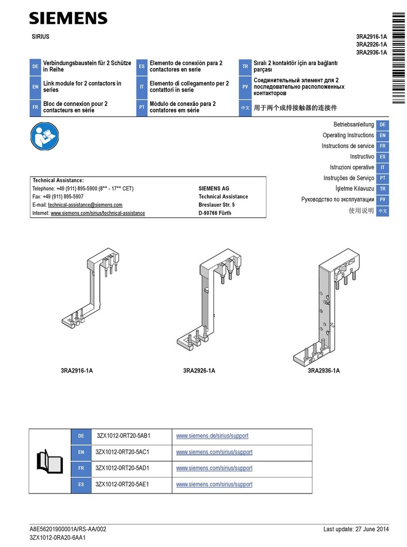
1)
1.1) 3SE5000-0AV01
1.2) 3SE5000-0AV02
1.3) 3SE5000-0AV03
mm
mm
mm
[[
[ˊ
[






1.4) 3SE5000-0AV04
1.5) 3SE5000-0AV06









r
r

[0
mm






r

r
[0



mm
X
5PP
5
;PP








mm
1.6) 3SE5000-0AV05
1.7) 3SE5000-0AV07
1.8) 3SE5000-0AV07-1AK2



r
r










Ø4,5
[0
mm
mm
5,5
27,7
40
5
50
15
77
46
29
15
mm
50
40
5
15
27.7
30
60
5.5
29
15
67.4
31
60
Technische Änderungen vorbehalten. Zum späteren Gebrauch aufbewahren.
Subject to change without prior notice. Store for use at a later date.
12/12 3ZX1012-0SE53-3DA1
© Siemens AG 2008
3)
3.1) 3SE511.-..V.. / 3SE513.-..V.. (IP66 / IP67)
3.2) 3SE512.-..V.. (IP66 / IP67)
36,5
0
16,3
37,3
20,6
32
32
M20x1,5
78
Ø 5,3
12,5
61
30
2
30
40,5
F≥30 N
0,4 mm/s ≤V≤1,5 m/s
mm
36,5
16,3
20
15,3
37,8
0
20,6
32
32
M20x1,5
Ø5,4
78
613,5
5,5
40
56
***)
F≥30 N
0,4 mm/s ≤V≤1,5 m/s
mm
3.3) 3SE521.-..V.. / 3SE523.-..V.. (IP65)
3.4) 3SE524.-..V.. (IP66 / IP67)
32,7
12,5
33
0
20.6
36
25
M20x1,5
Ø 4,3
68
4
13
22
20
31
3SE52340QV401AE0
(**)
Ø4x6
Ø7x3
22
22
3
6,9
13
35,9
4
5
Ø4x5
NSC0_00906
42,8
(****)
F≥30 N
0,4 mm/s ≤V≤1,5 m/s
mm
32,7
18,5
12,5
15
33
0
4
20,6
36
25
M20x1,5
53
Ø 4,3
13
4,4
42
40
22
20
5,5
50
***)
F≥30 N
0,4 mm/s ≤V≤1,5 m/s
mm
3) 3SE5000-0AW11
3) 3SE5000-0AW21
Technical Assistance:
SIEMENS AG, Technical Assistance
Würzburger Str. 121, D – 90766 Fürth
Tel: +49 (911) 895-5900 (8°° - 17°° CET); Fax: +49 (911) 895 -5907
E-mail: [email protected]
Internet: www.siemens.com/industrial-controls/technical-assistance
mm







[[
[ˊ
[



mm

Other manuals for SENTRON PAC RS485

1

Other Siemens Control Unit manuals

Siemens SIMATIC NET 6GK1110-1AA00 User manual

Siemens

Siemens SIMATIC NET 6GK1110-1AA00 User manual

Siemens SIMATIC S5 User manual

Siemens

Siemens SIMATIC S5 User manual

Siemens Milltronics BW500 User manual

Siemens

Siemens Milltronics BW500 User manual

Siemens SIMATIC FM 353 User manual

Siemens

Siemens SIMATIC FM 353 User manual

Siemens SIMATIC TDC User guide

Siemens

Siemens SIMATIC TDC User guide

Siemens SIPROTEC 4 7XT7100-0 A00/EE Series User manual

Siemens

Siemens SIPROTEC 4 7XT7100-0 A00/EE Series User manual

Siemens WFZ56 Series Installation and operation manual

Siemens

Siemens WFZ56 Series Installation and operation manual

Siemens MEM-1 User manual

Siemens

Siemens MEM-1 User manual

Siemens 3AK User manual

Siemens

Siemens 3AK User manual

Siemens AP 641 Service manual

Siemens

Siemens AP 641 Service manual

Siemens 3VL93 Series User manual

Siemens

Siemens 3VL93 Series User manual

Siemens SENTRON PROFINET Proxy SPP2000 User manual

Siemens

Siemens SENTRON PROFINET Proxy SPP2000 User manual

Siemens VVP47 Series User manual

Siemens

Siemens VVP47 Series User manual

Siemens DMS8000 MP4 Series Operating and maintenance instructions

Siemens

Siemens DMS8000 MP4 Series Operating and maintenance instructions

Siemens FDCL221-M User manual

Siemens

Siemens FDCL221-M User manual

Siemens 8DO User manual

Siemens

Siemens 8DO User manual

Siemens FCM2041-U3 User manual

Siemens

Siemens FCM2041-U3 User manual

Siemens SINAMICS G130 User manual

Siemens

Siemens SINAMICS G130 User manual

Siemens SINUMERIK Series Parts list manual

Siemens

Siemens SINUMERIK Series Parts list manual

Siemens SENTRON Series User manual

Siemens

Siemens SENTRON Series User manual

Siemens SINUMERIK 840C User manual

Siemens

Siemens SINUMERIK 840C User manual

Siemens TMM-1 User manual

Siemens

Siemens TMM-1 User manual

Siemens SIMATIC NET CP 1628 User manual

Siemens

Siemens SIMATIC NET CP 1628 User manual

Siemens VVF Series User manual

Siemens

Siemens VVF Series User manual

Popular Control Unit manuals by other brands

Eaton eNMC2 installation instructions

Eaton

Eaton eNMC2 installation instructions

Assa Abloy Securitron NL4 quick start guide

Assa Abloy

Assa Abloy Securitron NL4 quick start guide

Hubbell GAI-TRONICS E3 user manual

Hubbell

Hubbell GAI-TRONICS E3 user manual

Allen-Bradley ControlLogix 1756-OV32E installation instructions

Allen-Bradley

Allen-Bradley ControlLogix 1756-OV32E installation instructions

Watts Lync DigiTemp Jr V23 User guide/instruction manual

Watts

Watts Lync DigiTemp Jr V23 User guide/instruction manual

TUYA WRD2L product manual

TUYA

TUYA WRD2L product manual

ESMI FX-MC installation instructions

ESMI

ESMI FX-MC installation instructions

Wiznet WIZ1000 user manual

Wiznet

Wiznet WIZ1000 user manual

Eliwell UNICARD USB-TTL manual

Eliwell

Eliwell UNICARD USB-TTL manual

National Instruments NI 9213 Getting started

National Instruments

National Instruments NI 9213 Getting started

ITRON ITR9002 Technical reference guide

ITRON

ITRON ITR9002 Technical reference guide

Kitz XJ Operation manual

Kitz

Kitz XJ Operation manual

Franke DVS AC17-080 Installation & operating instructions

Franke

Franke DVS AC17-080 Installation & operating instructions

Emerson Baumann 25000 Lo-T Series instructions

Emerson

Emerson Baumann 25000 Lo-T Series instructions

Dembla GTV - 01 Series instruction manual

Dembla

Dembla GTV - 01 Series instruction manual

Numens 4001 Installation and service manual

Numens

Numens 4001 Installation and service manual

Advantech PCM-3810I Startup manual

Advantech

Advantech PCM-3810I Startup manual

3Com 3C54321 installation guide

3Com

3Com 3C54321 installation guide

manuals.online logo
manuals.online logoBrands
  • About & Mission
  • Contact us
  • Privacy Policy
  • Terms and Conditions

Copyright 2025 Manuals.Online. All Rights Reserved.