Siemens SIMATIC FM 353 User manual
Other Siemens Control Unit manuals

Siemens
Siemens SINAMICS V60 User manual
Siemens
Siemens Simatic S5 IP 240 User manual
Siemens
Siemens SIROTEC Technical manual

Siemens
Siemens Simatic TI405 User manual
Siemens
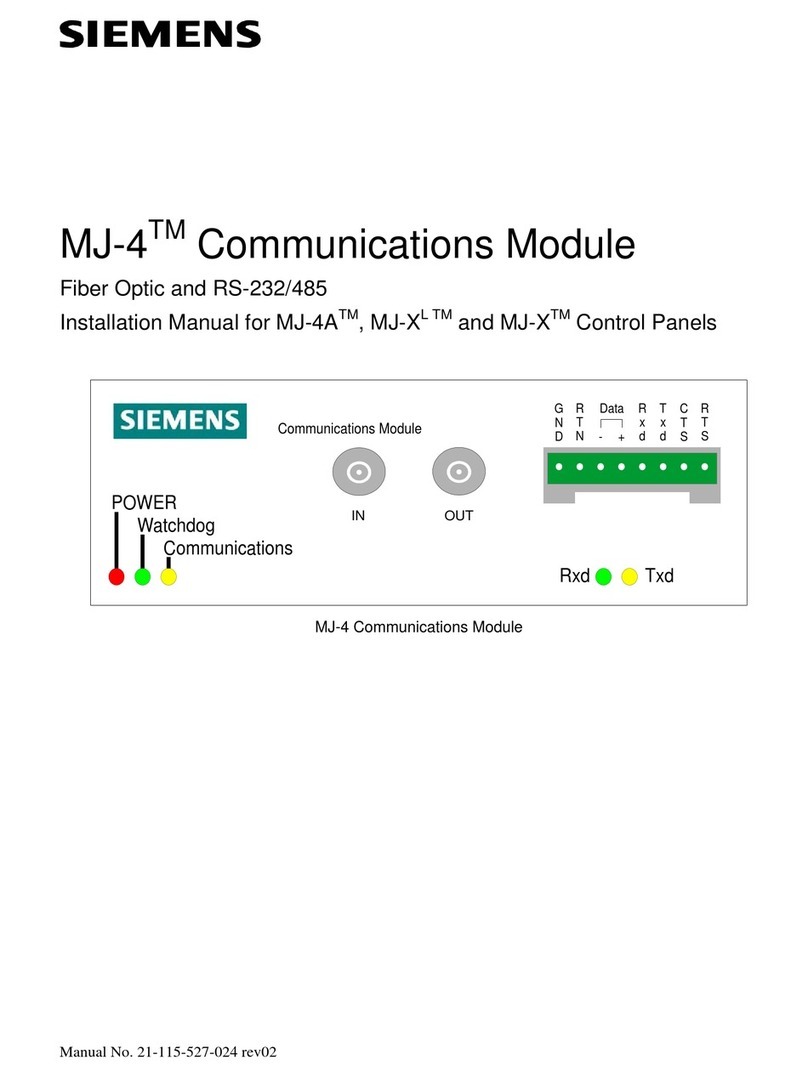
Siemens SIMATIC ET 200AL User manual
Siemens
Siemens MJ-4 Series User manual
Siemens
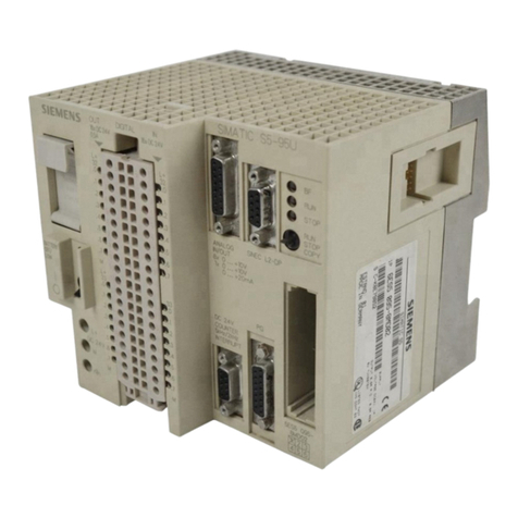
Siemens SIMATIC S5 User manual
Siemens
Siemens SINAMICS S120 Technical Document
Siemens
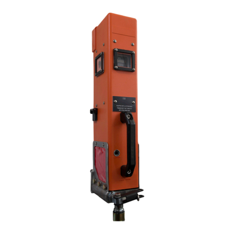
Siemens Q3920 User manual
Siemens
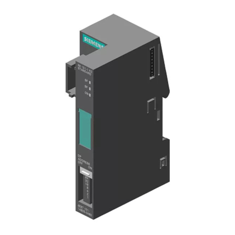
Siemens SIMATIC ET 200S IM151-1 FO STANDARD User manual
Siemens
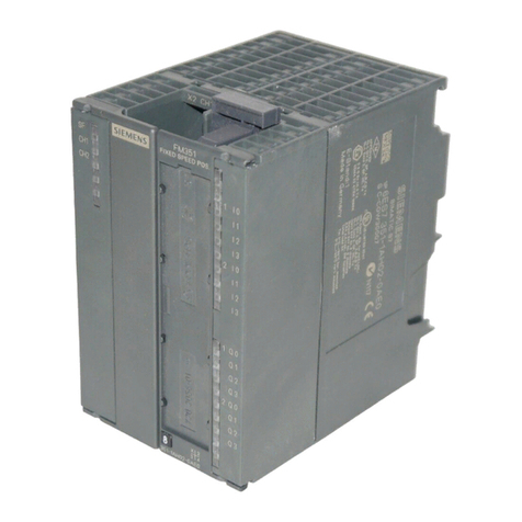
Siemens SIMATIC FM 351 User manual

Siemens
Siemens WF 723 C Operating instructions

Siemens
Siemens P1 BIM User manual

Siemens
Siemens NCU 7x0.3 PN Series User manual
Siemens
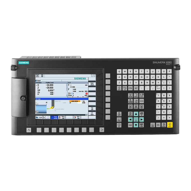
Siemens SINUMERIK 828D Turning User manual
Siemens
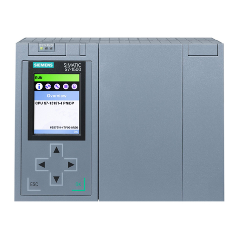
Siemens SIMATIC S7-1500R/H User manual
Siemens
Siemens Siprotec DNP3 IP Use and care manual
Siemens
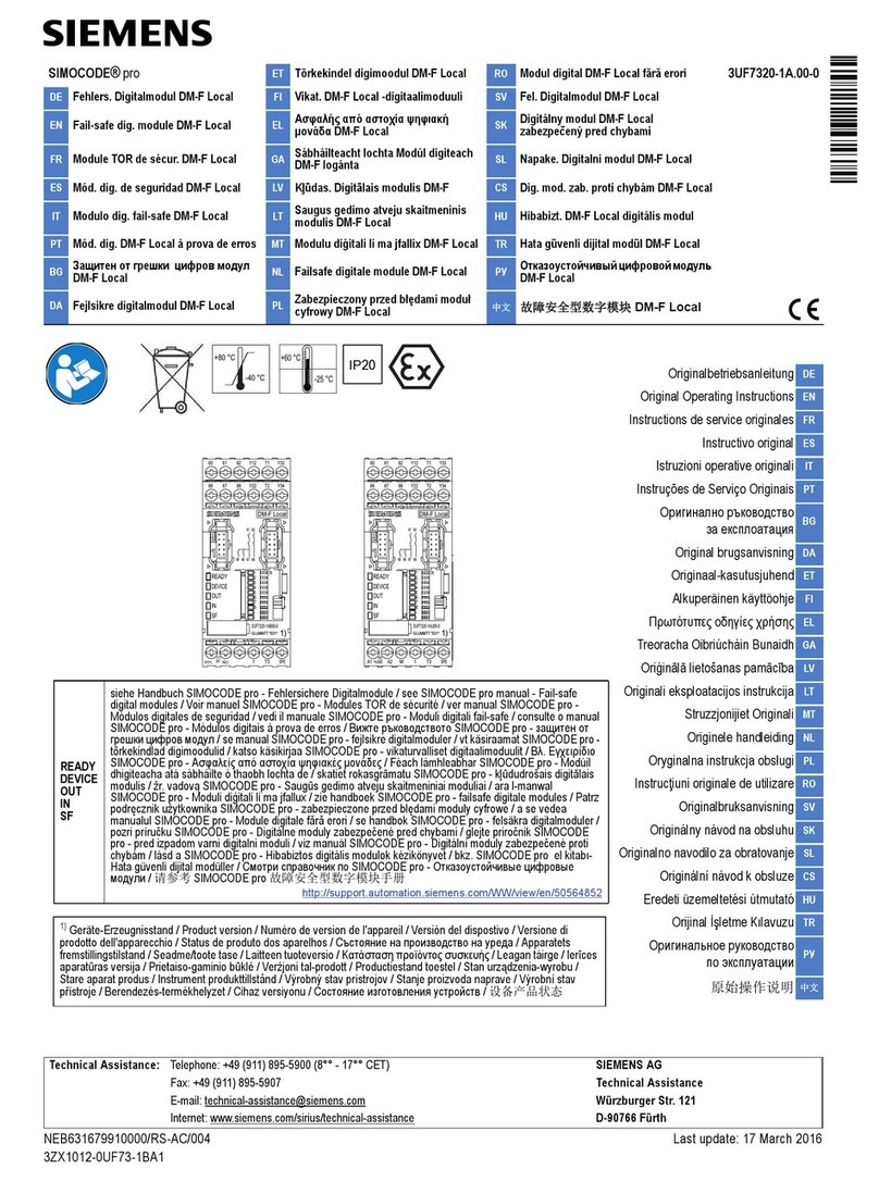
Siemens SIMOCODE pro DM-F Local User manual
Siemens
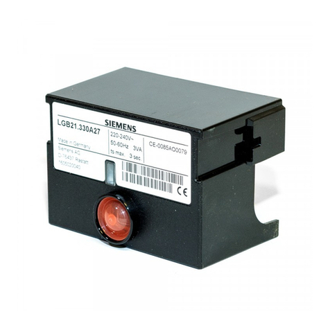
Siemens LGB21.130A17 User manual

Siemens
Siemens 3AD8 User manual
Popular Control Unit manuals by other brands

Festo
Festo Compact Performance CP-FB6-E Brief description

Elo TouchSystems
Elo TouchSystems DMS-SA19P-EXTME Quick installation guide

JS Automation
JS Automation MPC3034A user manual

JAUDT
JAUDT SW GII 6406 Series Translation of the original operating instructions

Spektrum
Spektrum Air Module System manual

BOC Edwards
BOC Edwards Q Series instruction manual

KHADAS
KHADAS BT Magic quick start

Etherma
Etherma eNEXHO-IL Assembly and operating instructions

PMFoundations
PMFoundations Attenuverter Assembly guide

GEA
GEA VARIVENT Operating instruction

Walther Systemtechnik
Walther Systemtechnik VMS-05 Assembly instructions

Altronix
Altronix LINQ8PD Installation and programming manual
