manuals.online logo
Brands
  1. Home
  2. •
  3. Brands
  4. •
  5. Siemens
  6. •
  7. Control Unit
  8. •
  9. Siemens AP 641 Service manual

Siemens AP 641 Service manual

DE
EN
A5E03410435A_RS-AH Seite 1 von 2 page 1 of 2
GAMMA instabus
AP 641 Raumautomationsbox
5WG1641-3AB01
AP 641 Room Control Box
5WG1641-3AB01
Bedien- und Montageanleitung
Operating and Mounting Instructions
Stand: September 2020
Issued: September 2020
Bild / Figure 1
Produkt- und Funktionsbeschreibung
Die quadratische Raumautomationsbox AP 641 ist mit 50 mm
Höhe für die Installation in der abgehängten Decke, im aufge-
ständerten Boden oder direkt auf eine Wand geeignet. Die Befes-
tigung erfolgt über Schrauben an den vier Ecken des Gehäuses.
Die Raumautomationsbox bietet acht Steckplätze für diese RS-/RL-
Module:
5WG1125-4AB23 Dezentrale Spannungsversorgung 80 mA
5WG1260-4AB23 Binäreingang, 4-fach, AC/DC, 12...230 V
5WG1510-2AB23 Binärausgabegerät (Relais), 2 x 10 A
5WG1512-4AB23 Schaltaktor (Relais), 1 x 16 A
5WG1513-4DB23 Binärausgabegerät (Relais), 3 x 6 A
5WG1520-2AB23 Jalousieaktor, 1 x 6 A
5WG1521-4AB23 Jalousieaktor, 2 x 6 A
5WG1525-2AB23 Universaldimmer, 1 x 250 VA
5WG1526-4DB23 Schalt-/Dimmaktor, 2 x AC 230V, 6 A,
1...10 V
5WG1510-2KB23 Thermoantriebaktor, 2 x 1,5 A
Die eingesteckten Module werden jeweils über eine Busklemme
mit einer internen Busleitung verbunden.
Für je vier Steckplätze enthält die Raumautomationsbox eine
Sammelschiene für PE- und N-Leiter. Damit können die PE-und N-
Leiter der in die Raumautomationsbox AP 641 eingeführten Lei-
tungen sicher aufgelegt werden.
Die Raumautomationsbox bietet 20 Leitungsdurchführungen.
Das Gehäuse der Raumautomationsbox sowie die Einführung von
Leitungen sind so gestaltet, dass IP54 erreicht wird. Leitungen
können an der Einführung gegen Zug durch Fixierung mit Kabel-
bindern gesichert werden.
Leiter für Netzspannungsversorgung und Lastkreise werden an
den Klemmen der eingesteckten Module angeschlossen.
Weitere Informationen
http://www.siemens.de/gamma
Montagebeispiel
siehe Bild 1
Technische Daten
Mechanische Daten
•Gehäuse: Kunststoff
•Abmessungen:
Länge x Breite x Höhe (in mm): 300 x 300 x 50
•Gewicht: ca. 1450 g
•Montage: mit vier Schrauben
•acht Steckplätze für RS-/RL-Module
•20 Leitungsdurchführungen, IP54, jeweils mit Fixierungsein-
richtung zur Zugentlastung
Anschlüsse
•Buslinie: Busklemme schraubenlos
0,6 ... 0,8 mm Ø eindrähtig, Abisolierlänge 5mm
•Interne Busleitung mit Busklemmen für acht RS-/RL-Module
•Netzspannung: 230 V AC ± 10 %, 50...60 Hz
Sammelschienenklemmen bzw. Klemmen von RS-/RL-Modu-
len
•Zwei Sammelschienen, ab Werk miteinander verbunden,
für PE- und N-Leiter, je Sammelschiene
N-Klemmen: 3 x 2,5 - 16 mm² und 14 x 1,5 - 4 mm²
PE-Klemmen: 3 x 2,5 - 16 mm² und 14 x 1,5 - 4 mm²
Elektrische Sicherheit
•Verschmutzungsgrad (nach IEC 60664-1): 2
•Schutzart (nach IEC 60529): IP 54
•Überspannungskategorie (nach IEC 60664-1): III
Umweltbedingungen
•Klimabeständigkeit: EN 50090-2-2
•Umgebungstemperatur im Betrieb: - 5 ... + 45 °C
•Lagertemperatur: - 25 ... + 70 °C
•rel. Feuchte (nicht kondensierend): 5 % bis 93 %
CE-Kennzeichnung
•gemäß Niederspannungsrichtlinie
Installationshinweise
•Die Raumautomationsbox kann für feste Installation in tro-
ckenen Innenräumen, zum Einbau in Zwischendecken und
Doppelböden sowie in Feuchträumen verwendet werden.
VGEFAHR
•Die Raumautomationsbox darf nur von einer zugelassenen
Elektrofachkraft installiert und in Betrieb genommen werden.
•Bei Arbeiten an der Raumautomationsbox ist darauf zu ach-
ten, dass die Raumautomationsbox freigeschaltet werden
kann.
•Bei Planung und Errichtung von elektrischen Anlagen sind die
einschlägigen Richtlinien, Vorschriften und Bestimmungen
des jeweiligen Landes zu beachten.
Product and Applications Description
The square AP 641 Room Control Box with a height of 50 mm is
designed for installation in a false ceiling, in a raised floor or di-
rectly on a wall. The Room ControlBox is affixed with screws at
the four corners of the housing.
The Room Control Box offers eight mounting locations for these
RS / RL modules:
5WG1125-4AB23 Decentralized Power Supply 80 mA
5WG1260-4AB23 Binary input, quadruple, AC/DC, 12...230 V
5WG1510-2AB23 Binary output (relay), 2 x 10 A
5WG1512-4AB23 Load switch (relay), 1 x 16 A
5WG1513-4DB23 Binary output (relay), 3 x 6 A
5WG1520-2AB23 Blind / shutter actuator, 1 x 6 A
5WG1521-4AB23 Blind / shutter actuator, 2 x 6 A
5WG1525-2AB23 Universal dimmer, 1 x 250 VA
5WG1526-4DB23 Switch-/dim actuator, 2 x AC 230V, 6 A,
1...10 V
5WG1510-2KB23 Thermal drive actuator, 2 x 1.5 A
The mounted modules are each connected to an internal bus line
via a bus terminal block.
For four mounting locations each the Room Control Box contains
a bus bar for PE and N conductors. This allow for secure connec-
tion of the PE and N conductors of the cables inserted into the
AP 641 Room Control Box.
The Room Control Box has 20 wire bushings. The housing of the
Room Control Boxas well as the bushings for wiring are designed
for IP 54. For strainrelief, cables can be secured atthecable bush-
ing with cable ties.
Line voltage supply and load conductors are terminated at the
terminals of the mounted modules.
Additional Information
http://www.siemens.com/gamma
Example of Operation
see figure 1
Technical Specifications
Physical Specifications
•housing: plastic
•dimensions:
Length x Width x Height (in mm): 300 x 300 x 50
•weight: approx. 1450 g
•mounting: with four screws
•eight mounting locations for RS / RL modules
•20 wire bushings, IP54, each with fixation provision for strain
relief
Connections
•Bus line: screwless bus terminal block (red-black)
0.6…0.8 mm Ø single core, strip insulation 5mm
•Internal bus line with bus terminal blocks for eight RS / RL
modules
•Mains power: 230 V AC ± 10 %, 50...60 Hz
bus bar terminals respectively terminals of RS / RL modules
•Two bus bars, connected to each other ex factory,
for PE and N conductors, per bus bar
N terminals: 3 x 2,5 - 16 mm² and 14 x 1,5 - 4 mm²
PE terminals: 3 x 2,5 - 16 mm² and 14 x 1,5 - 4 mm²
Electrical Safety
•Degree of pollution (according to IEC 60664-1): 2
•Type of protection (according to EN 60529): IP 54
•Overvoltage category (according to IEC 60664-1): III
Environmental specifications
•Climatic withstand capability: EN 50090-2-2
•Ambient temperature operating: - 5 ... + 45 °C
•Ambient temperature non-op.: - 25 ... + 70 °C
•relative humidity (non-condensing): 5 % bis 93 %
CE mark
•In accordance with the low voltage guideline
Installation notes
•The room control box may be used for permanent interior in-
stallations, for mounting in dry or wet rooms, in false ceilings
and raised floors.
VDANGER
•The room control box must be mounted and commissioned
by an authorized electrician.
•A safety disconnection of the room control box must be possi-
ble.
•For planning and construction of electric installations, the rel-
evant guidelines, regulations and standards of the respective
country are to be considered.
DE
EN
A5E03410435A_RS-AH Seite 2 von 3 page 2 of 3
Bild / Figure 2-a
Bild / Figure 2-b
Bild / Figure 2-c
Bild / Figure 2-d
Bild / Figure 2-e
Montage und Verdrahtung
Allgemeine Beschreibung
Die Raumautomationsbox ist zur Aufputzmontage an Decken,
Wänden, auf dem Boden oder anderen ebenen Flächen geeignet.
Die Löcher zur Schraubbefestigung der Raumautomationsbox be-
finden sich an den Ecken und sind ohne Öffnen des Gehäuses zu-
gänglich. Die Raumautomationsbox wird mit vier Schrauben be-
festigt.
Montage (Bild 2)
A1 Typenschild
A2 Loch für Schraubbefestigung der Raumautomationsbox
A3 Deckelschrauben (1/4-Dreh Schnellverschlüsse)
A4 Raumautomationsbox, Deckel
A5 Leitungsdurchführung
A6 SELV-Abdeckung für acht Modulplätze
A7 Lasche für Schlitzschraubendreher zum Lösen der SELV-Ab-
deckung
A8 Schutzabdeckung mit Ausbruchstellen (Pfeile) in SELV-
Abdeckung
A9 Raumautomationsbox, Basis
A10 Sammelschiene mit PE- / N-Klemmen
A11 PE-Leitung / N-Leitung zwischen den Sammelschienen
A12 Interne Busleitung mit Busklemmen
A13 Montageplatz für RS-/RL-Modul (1 ... 8)
A14 RS-Modul (getrennt zu bestellen)
A15 RL-Modul (getrennt zu bestellen)
•Montage der Raumautomationsbox:
- Abstand der Bohrlöcher zur Schraubbefestigung: 289 mm
(siehe Bild 2-a)
- Befestigen Sie die Raumautomationsbox an den Befestigungs-
punkten (A2) (siehe Bild 2-b) mit Schrauben (z.B. 4,5 x 50 mm,
nicht im Lieferumfang).
•Entfernen des Deckels der Raumautomationsbox (Bild 2-b):
- Drehen Sie die Schnellverschlussschrauben (A3) eine Viertel-
drehung gegen den Uhrzeigersinn.
- Heben Sie den Deckel (A4) mit den Verschlussschrauben ab.
•Montage / Demontage der SELV-Abdeckung (Bild 2-c):
- Montage:
SELV-Abdeckung (A6) gerade aufsetzen, einfädeln und nach
unten drücken bis die Schnapper einrasten.
- Demontage:
Mit Schlitzschraubendreher SELV-Abdeckung (A6) an der La-
sche (A7) auf beiden Seiten nach außen drücken und nach
obenhin wegnehmen.
- Ausbrechen der Schutzabdeckung (Bild 2-d):
Die SELV-Abdeckung (A6) wird mit acht verschlossenen Schutz-
abdeckungen (A8) ausgeliefert, die einzeln ausgebrochen wer-
den können.
Für jeden verwendeten Steckplatz (A13) muss in der SELV-Ab-
deckung (A6) die zugehörige Schutzabdeckung (A8) ausgebro-
chen werden.
•Montage / Demontage der RS-/RL-Module (Bild 2-e):
An jedem der acht Steckplätze (A13) der Raumautomationsbox
(A6) kann ein RS-Modul (A14) oder ein RL-Modul (A15) installiert
werden. Die Montage der RS- und RL-Module wird in dieser Be-
dien- und Montageanleitung allgemein beschrieben.
Hinweise zu Leitungsanschluss und Inbetriebnahme bestimmter
Module ist der jeweiligen Dokumentation zu diesem Modul zu
entnehmen.
Installation and Wiring
General description
The Room Control Box is designed for on-surface mounting on
ceilings, walls, on the floor or any even surface. The holes for
screw fastening of the Room Control Box are located on the cor-
ners of the box and are accessible without opening the housing.
The Room Control Box is affixed with four screws.
Mounting (figure 2)
A1 Product label
A2 Hole for screw fastening of Room Control Box
A3 Lid screws (quarter-turn quick fastening screws)
A4 Room Control Box, Lid
A5 Cable bushing
A6 SELV (Class 2) cover for eight modules
A7 Lug to release SELV (Class 2) cover with a screw driver
A8 Protective cover with prepared break-outs (arrows) in
SELV (Class 2) cover
A9 Room Control Box, base
A10 Bus bar with PE / N terminals
A11 PE wire / N wire between bus bars
A12 Internal bus wiring with bus terminal blocks
A13 Mounting location for RS / RL module (1 ... 8)
A14 RS module (to be ordered separately)
A15 RL module (to be ordered separately)
•Mounting of the Room Control Box:
- Distance between drill holes for screw fastening: 289 mm
(see figure 2-a)
- Fix the Room Control Box at the fixation points (A2) (see figure
2-b) with screws (e.g. 4.5 x 50 mm, to be sourced separately).
•Removing the lid of the Room Control Box (figure 2-b):
- Turn the quick fastening screws (A3) a quarter turn counter
clock-wise.
- Remove the lid (A4) with the quarter-turn quick fastening
screws.
•Mounting / Dismounting the SELV (class 2) cover (figure 2-c):
- Mounting:
Insert the SELV (Class 2) cover (A6) in a level position, find the
mounting position, and then push it down until the catches
snap audibly.
- Dismounting:
Move the SELV (Class 2) cover (A6) outwards with a screw
driver inserted into the lug (A7)and then lift it upwards.
- Breaking out the protective cover (figure 2-d):
The SELV (Class 2) cover (A6) is delivered with eight closed
protective covers (A8). Each of these can be removed individu-
ally.
For each mounting location (A13) used the associated protec-
tive cover (A8) of the SELV (Class 2) cover (A6) has to be re-
moved.
•Mounting / Dismounting of RS /RL modules (figure 2-e):
A RS module (A14) or an RL module (A15) may be installed at any
of the eight mounting locations (A13) of the Room Control Box.
Mounting of the RS and RL modules is described generically in
these mounting and operating instructions.
Notes on wiring and commissioning of specific modules may be
found in the respective documentation for that module.
DE
EN
A5E03410435A_RS-AH Seite 3 von 4 page 3 of 4
Bild / Figure 3-a
Bild / Figure 3-b
Bild / Figure 3-c
Bild / Figure 3-d
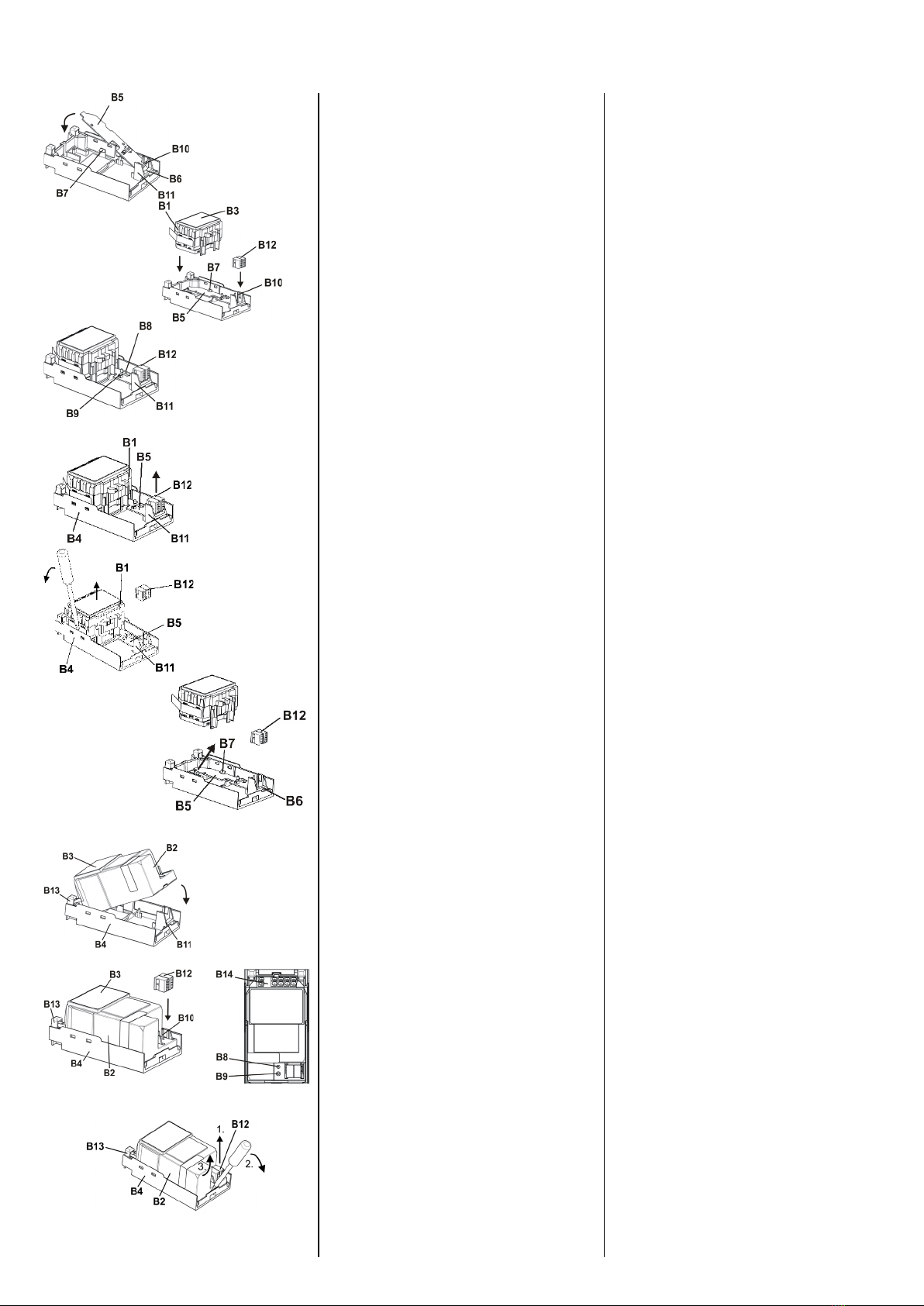
Montage von RS- / RL-Modulen (Bild 3)
B1 RS-Modul
B2 RL-Modul
B3 Typenschild (mit Feld für physikalische Adresse des Mo-
duls)
B4 Steckplatz für RS-/RL-Modul in AP 641 Raumautomations-
box
B5 Busverbindungsmodul mit Busstiften für Busklemme, LED
zur Anzeige Normalmodus (LED aus) oder Adressiermodus
(LED ein), Lerntaste und Kontakten zum RS-Modul
B6 Einsteckpunkt für Busverbindungsmodul des RS-Moduls
B7 Einschnappunkt für Busverbindungsmodul des RS-Moduls
B8 Lerntaste zum Umschalten zwischen Normalmodus und
Adressiermodus zur Übernahme der physikalischen Ad-
resse
B9 LED zur Anzeige Normalmodus (LED aus) oder
Adressiermodus (LED ein); sie erlischt automatisch nach
Übernahme der physikalischen Adresse
B10 Busstifte zum Aufstecken der Busklemme
B11 Steckplatz für Busklemme
B12 Busklemme für eindrähtige Leiter mit 0,6 ... 0,8mm ∅
B13 Einhängepunkt für Montagehaken des RL-Moduls
B14 Anschlussklemmen
•Montage eines RS-Moduls (Bild 3-a):
- AP 641: Entfernen Sie den Deckel und die SELV-Abdeckung
- Entfernen Sie die Busklemme (B12) vom Steckplatz (B11).
- Stecken Sie das Busverbindungsmodul (B5) so in den Einsteck-
punkt (B6) für das Busverbindungsmodul ein, daß die Busstifte
(B10) zum Steckplatz der Busklemme (B11) zeigen.
- Drücken Sie das Busverbindungsmodul (B5) so nach unten, daß
es in die Halterung (B7) einschnappt.
- Stecken Sie das RS-Modul (B1) von oben so ein, daß die An-
schlussklemmen (B14) weg von dem Busklemmensteckplatz
(B11) zeigen. Das Typenschild (B3) ist oben.
- Stecken Sie die Busklemme (B12) des Steckplatzes (B4) auf die
Busstifte (B10) des Busverbindungsmoduls (B5).
- Zur Vergabe der physikalischen Adresse drücken Sie die Lern-
taste (B8) für maximal 2 Sekunden. Die eingeschaltete LED
(B9) zeigt den Adressiermodus an. Die LED erlischt automatisch
nach Übernahme der physikalischen Adresse.
- Montieren Sie den Deckel und die SELV-Abdeckung wieder.
•Demontage eines RS-Moduls (Bild 3-b):
- AP 641: Entfernen Sie den Deckel und die SELV-Abdeckung
- Lösen Sie die Leitungen aus den Anschlussklemmen (B14).
- Ziehen Sie die Busklemme (B12) ab
- Lösen Sie das RS-Modul (B1), indem Sie das Modul jeweils seit-
lich mit einem Schlitzschraubendreher aus der Verschnappung
lösen.
- Ziehen Sie das RS-Modul (B1) aus dem Steckplatz (B4) heraus.
- Soll ein RL-Modul (B2) in den Steckplatz eingesetzt werden, lö-
sen Sie das Busverbindungsmodul (B5) am Einschnappunkt
(B7), heben es an und ziehen es aus dem Einsteckpunkt (B6)
heraus.
- Montieren Sie den Deckel und die SELV-Abdeckung wieder.
•Montage eines RL-Moduls (Bild 3-c):
- AP 641: Entfernen Sie den Deckel und die SELV-Abdeckung
- Hängen Sie das RL-Modul (B2) in die Einhängung (B13) des
Steckplatzes (B4). Die Anschlussklemmen (B14) zeigen weg
von dem Busklemmensteckplatz (B11). Das Typenschild (B3) ist
oben.
- Klappen Sie das RL-Modul (B2) nach unten bis es im Steckplatz
(B4) einrastet.
- Stecken Sie die Busklemme (B12) des Steckplatzes (B4) auf die
Busstifte (B10) des RL-Moduls (B2).
- Zur Vergabe der physikalischen Adresse drücken Sie die Lern-
taste (B8) für maximal 2 Sekunden. Die eingeschaltete LED
(B9) zeigt den Adressiermodus an. Die LED erlischt automatisch
nach Übernahme der physikalischen Adresse.
- Montieren Sie den Deckel und die SELV-Abdeckung wieder.
•Demontage eines RL-Moduls (Bild 3-d):
- AP 641: Entfernen Sie den Deckel und die SELV-Abdeckung
- Lösen Sie die Leitungen aus den Anschlussklemmen (B14).
- Ziehen Sie die Busklemme (B12) ab.
- Lösen Sie das RL-Modul (B2), indem Sie das Modul auf der
Busklemmenseite mit einem Schlitzschraubendreher aus der
Verschnappung lösen.
- Klappen Sie das RL-Modul (B2) hoch, ziehen es nach unten aus
der Einhängung (B13) und entfernen es aus dem Steckplatz
(B4).
- Montieren Sie den Deckel und die SELV-Abdeckung wieder.
Mounting of RS / RL modules (Figure 3)
B1 RS module
B2 RL module
B3 Type label (with space for physical address of the module)
B4 Mounting location for RS / RL module in AP 641 Room Con-
trol Box
B5 Bus connection module with bus connection pins for bus
terminal block, LED for indicating normal operating mode
(LED off) or addressing mode (LED on), Learning button
and contacts to RS module
B6 Insertion point for bus connection module of the RS mod-
ule
B7 Snap-in point for bus connection module of the RS module
B8 Learning button for switching between normal operating
mode and addressing mode and for receiving the physical
address
B9 LED for indicating normal operating mode (LED off) or ad-
dressing mode (LED on); returns to normal operating mode
automatically after receiving the physical address
B10 Bus connection pins for connection of the bus terminal
block
B11 Insertion point for bus terminal block
B12 Bus terminal block for single core conductors with
0,6...0,8 mm Ø
B13 Hinge joint for mounting hinge of the RL module
B14 Terminals
•Mounting of a RS module (Figure 3-a):
- AP 641: Remove the box cover and the SELV (Class 2) cover
- Insert the bus connection module (B5) in such a way into the
insertion point (B6) for the bus connection module that the
bus connection pins (B10) point to the insertion point for the
bus terminal (B11).
- Press the bus connection module (B5) down until it snaps into
the locking position (B7).
- Insert the RS module (B1) from the top with the terminals
(B14) pointing away from the bus terminal insertion point
(B11). The type label (B3) is on top.
- Insert the bus terminal (B12) of the mounting location (B4)
onto the bus connection pins (B10) of the bus connection
module (B5).
- For assignment of the Physical Address press the learning but-
ton (B8) for a maximum of 2 seconds. The addressing mode is
indicated when the LED is on (B9). It returns to normal operat-
ing mode (LED Off) automatically after receiving the physical
address.
- Mount the lid and the SELV (Class 2) cover again.
•Dismounting an RS module (Figure 3-b):
- AP 641: Remove the box cover and the SELV (Class 2) cover
- Remove the wiring from the terminals (B14).
- Remove the bus terminal (B12).
- To remove the RS module (B1), insert a screw driver between
the module and the mounting location siding and push it up to
release it from the snap-in hooks. Do this on both sides.
- Pull the RS module (B1) from the mounting location (B4).
- If an RL module (B2) shall be inserted into the mounting loca-
tion, detach the bus connection module (B5) from the snap-in
point (B7), swivel it up and pull it out of the insertion point
(B6).
- Mount the lid and the SELV (Class 2) cover again.
•Mounting of an RL module (Figure 3-c):
- AP 641: Remove the box cover and the SELV (Class 2) cover
- Insert the RL module (B2) into the hinge (B13) of the mounting
location (B4). The terminals (B14) point away from the inser-
tion point for the bus terminal (B11). The type label (B3) is on
top.
- Swivel the RL module (B2) down until it audibly snaps into the
mounting location (B4).
- Insert the bus terminal (B12) of the mounting location (B4)
onto the bus connection pins (B10) of the RL module (B2).
- For assignment of the Physical Address press the learning but-
ton (B8) for a maximum of 2 seconds. The addressing mode is
indicated when the LED is on (B9). It returns to normal operat-
ing mode (LED Off) automatically after receiving the physical
address.
- Mount the lid and the SELV (Class 2) cover again.
•Dismounting an RL module (Bild 3-d):
- AP 641: Remove the box cover and the SELV (Class 2) cover
- Remove the wiring from the terminals (B14).
- Remove the bus terminal (B12).
- To remove the RL module (B2), insert a screw driver between
the module and the mounting location on the bus terminal
side and push it up to release it from the snap-in hooks.
- Swivel the RL module (B2) up, pull it down out of the hinge
(B13) and remove it from the mounting location (B4).
- Mount the lid and the SELV (Class 2) cover again.
DE
EN
A5E03410435A_RS-AH Seite 4 von 4 page 4 of 4
C2
C2.2 C2.1
C2.3
Bild / Figure 4
D2
D2.4
5 mm
D2
D2.4
25...35 mm
D1
Bild / Figure 5
Bild / Figure 6
Verdrahtung
Busklemme abziehen/aufstecken (Bild 4)
Die Busklemme (C2) besteht aus zwei Teilen (C2.1, C2.2) mit je
vier Klemmkontakten. Es ist darauf zu achten, dass die beiden
Prüfbuchsen (C2.3) weder mit dem Busleiter (versehentlicher
Steckversuch) noch mit dem Schraubendreher (beim Versuch
die Busklemme zu entfernen) beschädigt werden.
Busklemme abziehen (Bild 4)
- Den Schraubendreher vorsichtig in den Drahteinführungs-
schlitz des schwarzen Teils der Busklemme (C2,2) einführen
und
- die Busklemme (C2) aus dem Modul herausziehen.
Hinweis
Busklemme nicht von unten heraushebeln! Kurzschlussgefahr!
Busklemme aufstecken (Bild 4)
- Die Busklemme (C2) in die Führungsnut des Moduls stecken
und
- die Busklemme (C2) bis zum Anschlag nach unten drücken.
Anschließen der Busleitung (Bild 5)
- Die Busklemme (D1) ist für eindrähtige Leiter mit
0,6 ... 0,8mm Ø geeignet.
- Den Leiter (D2) ca. 5mm abisolieren und in Klemme (D1) ste-
cken (rot = +, grau = -)
Abklemmen der Busleitung (Bild 5)
- Die Busklemme (D2) abziehen und den Leiter (D2.4) der Bus-
leitung, bei gleichzeitigem Hin- und Herdrehen, herauszie-
hen.
Netz-/Laststromkreis anschließen und abklemmen: siehe Bild 6
Leiter anschließen
- Die Anschlüsse für die Leiter bestehen aus schraubenlosen
Steckklemmen (E1).
- Die Leiter (E2) ca. 9 ... 10mm abisolieren und in die
Klemmen (E1) stecken.
- Die Klemmen sind für das Einstecken zweier Leiter ausgelegt,
so dass ein Durchschleifen über die Klemmen möglich ist.
Hinweis:
Die Klemmen dürfen maximal mit 16A belastet werden.
Leiter abklemmen
Mit dem Schraubendreher auf die Verriegelung der Klemme (F1)
drücken und den (die) Leiter (F2) aus der Klemme (F1) ziehen.
Wiring
Slipping off/on bus terminal blocks (figure 4)
The bus terminal block (C2) consists of two components (C2.1
and C2.2) with four terminal contacts each.Take care not to dam-
age the two test sockets (C2.3) by accidentally connecting them
to the bus cable or with the screw driver (e.g. when attempting
to unplug the bus terminal block).
Slipping off bus terminal blocks (figure 4)
- Carefully put the screw driver to the wire insertion slit of the
bus terminal block’s grey component (C2.2) and
- pull the bus terminal block (C2) from the module.
Note
Don’t try to remove the bus terminal block from the bottom side.
There is a risk of shorting-out the device!
Slipping on bus terminal blocks (figure 4)
- Slip the bus terminal block (C2) onto the guide slot of the
module and
- press the bus terminal block (C2) down to the stop.
Connecting bus cables (figure 5)
- The bus terminal block (D1) can be used with single core con-
ductors Ø 0.6…0.8 mm.
- Remove approx. 5 mm of insulation from the conductor (D2)
and plug it into the bus terminal block (D1)
(red = +, grey = -)
Disconnecting bus cables (figure 5)
- Unplug the bus terminal block (D1) and remove the bus cable
conductor (D2) while simultaneously wiggling it.
Connecting/disconnecting mains and load circuit: see figure 6
Connect wires
- The load circuits are connected via screwless plug-in terminals
(E1).
- Remove approx. 9…10 mm of insulation from the wire (E 1.1)
and plug it into the terminal (E1).
- The terminals are designed for connection of two wires allow-
ing to loop through the terminal block.
Note:
The maximum permissible terminal load current is 16A.
Remove wires
Press the terminal interlocking of the terminal (F1) with a
screw-driver and remove the wire (F2) from the terminal (F1).
Technical Support
+49 (911) 895-7222
+49 (911) 895-7223
support.automation@siemens.com
www.siemens.de/automation/support-request
Allgemeine Hinweise
•Die Bedienungsanleitung ist dem Kunden auszuhändigen.
•Ein defektes Gerät ist mit einem Rücklieferschein der zuständi-
gen Vertriebsniederlassung zurückzusenden.
•Bei zusätzlichen Fragen zum Produkt wenden Sie sich bitte an
unseren Technical Support.
General Notes
•The operating instructions must be handed over to the client.
•A faulty device shall be returned with a Return Good Note for
Service provided by the appropriate Siemens sales office.
•If you have further questions concerning the product please
contact our technical support.

This manual suits for next models

1

Other Siemens Control Unit manuals

Siemens Simatic 6ES7132-4HB01-0AB0 User manual

Siemens

Siemens Simatic 6ES7132-4HB01-0AB0 User manual

Siemens SITRANS F M MAGFLO series User manual

Siemens

Siemens SITRANS F M MAGFLO series User manual

Siemens SIMATIC ET 200SP IM 155-6 PN/2 HF User manual

Siemens

Siemens SIMATIC ET 200SP IM 155-6 PN/2 HF User manual

Siemens SIMATIC ET 200eco PN User manual

Siemens

Siemens SIMATIC ET 200eco PN User manual

Siemens LMV36.520A1 Operator's manual

Siemens

Siemens LMV36.520A1 Operator's manual

Siemens SIRIUS ACT 3SU18 N Series User manual

Siemens

Siemens SIRIUS ACT 3SU18 N Series User manual

Siemens SIJECT 16i User manual

Siemens

Siemens SIJECT 16i User manual

Siemens SINUMERIK 840D sl Parts list manual

Siemens

Siemens SINUMERIK 840D sl Parts list manual

Siemens SIRIUS ACT 3ZX1012-0SU14-1KA1 User manual

Siemens

Siemens SIRIUS ACT 3ZX1012-0SU14-1KA1 User manual

Siemens 7SC80 User manual

Siemens

Siemens 7SC80 User manual

Siemens AC75 User manual

Siemens

Siemens AC75 User manual

Siemens RUGGEDCOM RS900F User manual

Siemens

Siemens RUGGEDCOM RS900F User manual

Siemens VVG44.15-0.4S Owner's manual

Siemens

Siemens VVG44.15-0.4S Owner's manual

Siemens SIMOCODE pro DM-F Local User manual

Siemens

Siemens SIMOCODE pro DM-F Local User manual

Siemens SIMATIC ET 200SP User manual

Siemens

Siemens SIMATIC ET 200SP User manual

Siemens K60R User manual

Siemens

Siemens K60R User manual

Siemens 6ES5-424 Product manual

Siemens

Siemens 6ES5-424 Product manual

Siemens TMM-1 User manual

Siemens

Siemens TMM-1 User manual

Siemens SIRIUS 3RK3211 User manual

Siemens

Siemens SIRIUS 3RK3211 User manual

Siemens SIMATIC 8DO DC24V/0.5 A User manual

Siemens

Siemens SIMATIC 8DO DC24V/0.5 A User manual

Siemens SIMATIC ET 200SP User manual

Siemens

Siemens SIMATIC ET 200SP User manual

Siemens SIRIUS Star-Delta Combination S2 User manual

Siemens

Siemens SIRIUS Star-Delta Combination S2 User manual

Siemens Simatic S7-1500 User manual

Siemens

Siemens Simatic S7-1500 User manual

Siemens SIMATIC RF120C User manual

Siemens

Siemens SIMATIC RF120C User manual

Popular Control Unit manuals by other brands

resideo Braukmann D04FM installation instructions

resideo

resideo Braukmann D04FM installation instructions

Deep Sea Electronics Plc DSE5110 operating manual

Deep Sea Electronics Plc

Deep Sea Electronics Plc DSE5110 operating manual

VPro BF Series Installation, operation & maintenance instructions

VPro

VPro BF Series Installation, operation & maintenance instructions

Sensitron MULTISCAN++S1 Installation and use manual

Sensitron

Sensitron MULTISCAN++S1 Installation and use manual

Spirax Sarco PM6 Installation and maintenance instructions

Spirax Sarco

Spirax Sarco PM6 Installation and maintenance instructions

AQUATROL 69 Installation & operating instructions

AQUATROL

AQUATROL 69 Installation & operating instructions

Betts EV1XAETM-AAVB Installation and maintenance manual

Betts

Betts EV1XAETM-AAVB Installation and maintenance manual

SMC Networks JSXH31-CP X2 Series Operation manual

SMC Networks

SMC Networks JSXH31-CP X2 Series Operation manual

MPP Solar Wi-Fi Card user manual

MPP Solar

MPP Solar Wi-Fi Card user manual

Beckhoff AX2090-BW5 Series Documentation

Beckhoff

Beckhoff AX2090-BW5 Series Documentation

SMC Networks VQC2000 Installation and maintenance manual

SMC Networks

SMC Networks VQC2000 Installation and maintenance manual

Kemper KTS ComLog module operating instructions

Kemper

Kemper KTS ComLog module operating instructions

Honeywell VS8510 manual

Honeywell

Honeywell VS8510 manual

steute SRM 21 RT2 Mounting and wiring instructions

steute

steute SRM 21 RT2 Mounting and wiring instructions

Snazzy FX Kitty Eyes Assembly guide

Snazzy FX

Snazzy FX Kitty Eyes Assembly guide

AMCI 7551 Manual addendum

AMCI

AMCI 7551 Manual addendum

Monacor ATT-212H/WS instructions

Monacor

Monacor ATT-212H/WS instructions

LGB 55080 manual

LGB

LGB 55080 manual

manuals.online logo
manuals.online logoBrands
  • About & Mission
  • Contact us
  • Privacy Policy
  • Terms and Conditions

Copyright 2025 Manuals.Online. All Rights Reserved.