manuals.online logo
Brands
  1. Home
  2. •
  3. Brands
  4. •
  5. Siemens
  6. •
  7. Industrial Equipment
  8. •
  9. Siemens SITOP PSU400S User manual

Siemens SITOP PSU400S User manual

© Siemens, All rights reserved Ⓟ 2014
1
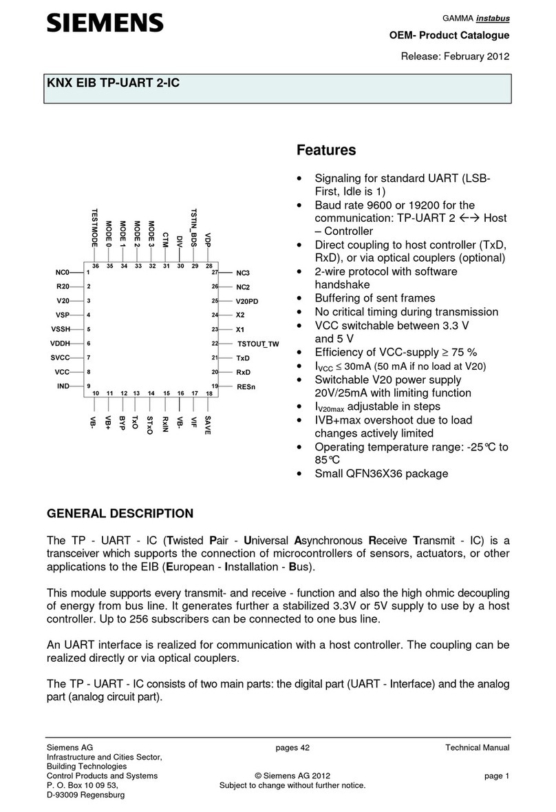
SITOP PSU400S
6EP1733-2BA00-0AA0 24 V / 5 A
Betriebsanleitung (kompakt)
Operating Instructions (compact)
Bild 1: Ansicht Gerät
Figure 1: View of unit
Bild 2: Montage
Figure 2: Mounting
DEUTSCH
Beschreibung
Die SITOP-Stromversorgungen
PSU400S sind Einbaugeräte, Schutzart
IP20, Schutzklasse I.
Primär getaktete Stromversorgungen
zum Anschluss an SELV
Gleichspannungsnetze mit
Nennspannung 48V
Siehe auch Bild 1
Sicherheitshinweise
ACHTUNG
Der einwandfreie und sichere Betrieb
dieses Gerätes/Systems setzt
sachgemäßen Transport, sachgemäße
Lagerung, Aufstellung und Montage
sowie sorgfältige Bedienung und
Instandhaltung voraus.
Dieses Gerät/System darf nur unter
Beachtung der Instruktionen und
Warnhinweise der zugehörigen
Technischen Dokumentation
eingerichtet und betrieben werden.
Nur qualifiziertes Personal darf das
Gerät/System installieren und in Betrieb
setzen.
Bei Ausgangsleistungen über der
Nennleistung (Nutzung Ia,nenn>100 %)
kann der Eingangsstrom Ie den
Nennstrom Ie,nenn übersteigen .
Montage
Montage auf Normprofilschiene
DIN EN 60715-TH35-15/7,5.
Das Gerät ist so zu montieren, dass die
Eingangs- und Ausgangsklemmen unten
sind.
Unterhalb und oberhalb des Gerätes
muss mindestens ein Freiraum von je
50 mm eingehalten werden (max.
Kabelkanaltiefe 50 mm).
Bei Installation des Gerätes in
explosionsgefährdeter Umgebung
(II 3G Ex nA nC IIC T4 Gc) ist dieses
in einen Verteilerkasten mit Schutzart
IP54 oder höher einzubauen. Dieser
Verteilerkasten muss den Anforderungen
der EN 60079-15:2010 entsprechen.
Angewandte Normen: EN 60079-0:2009
und EN 60079-15:2010
Siehe auch Bild 2
Siehe auch Bild 6
ENGLISH
Description
The PSU400S SITOP power supplies
are built-in units, IP20 degree of
protection, protection class I.
Primary switched-mode power supplies
for connection to DC system with rated
voltages of 48 V; +24 V DC output
voltage, isolated, short-circuit-proof and
idling-proof.
See also Figure 1
Safety notes
NOTICE
Appropriate transport, proper storage,
mounting, and installation, as well as
careful operation and service, are
essential for the error-free, safe and
reliable operation of the device/system.
Setup and operation of this
device/system are permitted only if the
instructions and warnings of the
corresponding documentation are
observed.
Only qualified personnel are allowed to
install the device/system and set it into
operation.
Warning: Do not operate voltage
adjustment when an explosive
atmosphere may be present.
In the case of output powers above the
rated power (use Ia,rated>100%) the input
current Ie can exceed the rated current
Ie,rated.
Assembling
Mounted on a standard mounting rail
DIN EN 60715-TH35-15/7,5.
The device must be mounted in such a
way that the input and output terminals
are at the bottom.
A clearance of at least 50 mm must be
maintained above and below the device
(max. cable channel depth 50 mm).
If the device is to be used in a hazardous
area ( II 3G Ex nA nC IIC T4 Gc) it
must be installed in a distributor box with
degree of protection IP54 or higher. This
distributor box must correspond with the
specifications of EN 60079-15:2010.
Applicable standards: EN 60079-0:2009
and EN 60079-15:2010
See also Figure 2
See also Figure 6
2
Bild 3: Input ①
Figure 3: Input ①
Bild 4: Output ②
Figure 4: Output ②
Bild 5: Klemmendaten
Figure 5: Terminal data
Anschließen
WARNUNG
Vor Beginn der Installations- oder
Instandhaltungsarbeiten ist der
Hauptschalter der Anlage auszuschalten
und gegen Wiedereinschalten zu
sichern. Bei Nichtbeachtung kann das
Berühren spannungsführender Teile Tod
oder schwere Körperverletzung zur
Folge haben. Die Betätigung des
Potenziometers ist nur mittels isoliertem
Schraubendreher zulässig. Für die
Installation der Geräte sind die
einschlägigen länderspezifischen
Vorschriften zu beachten.
Der Anschluss der
Versorgungsspannung muss gemäß
IEC 60364 und EN 50178 ausgeführt
werden.
Siehe auch Bild 3
Siehe auch Bild 4
Siehe auch Bild 5
Aufbau
① AC-Eingang
② DC-Ausgang
④ Potenziometer 22,8 – 28 V
⑤ Kontrollleuchte (24 V O.K.)
⑥ Hutschienenentriegelung
⑦ Konvektion
⑧ Freiraum oberhalb/unterhalb
Siehe auch Bild 6
Betriebsmodus
Signalisierung
⑤ LED grün: Ausgangsspannung OK
Siehe auch Bild 4
Technische Daten
6EP1733-2BA00-0AA0 24 V/5,0 A
① Eingangsgrößen
Eingangsnennspannung Ue nenn: DC 48V
Spannungsbereich:
DC 30-75,5V (Derating beachten)
Eingangsnennstrom Ie nenn
bei Nennlast:
2,9A
Eingangssicherung: intern
Verpolschutz Eingang: ja
Empfohlene Absicherung
Charakteristik C: 6A
Leistungsaufnahme bei Nennbetrieb
(typisch)
Connecting
WARNING
Before installation or maintenance work
can begin, the system's main switch
must be switched off and measures
taken to prevent it being switched on
again. If this instruction is not observed,
touching live parts can result in death or
serious injury. It is only permissible to
use an insulated screwdriver when
actuating the potentiometer. For
installation of the devices, the relevant
country-specific regulations must be
observed.
The supply voltage must be connected in
accordance with IEC 60364 and
EN 50178.
See also Figure 3
See also Figure 4
See also Figure 5
Structure
① AC input
② DC output
④ Potentiometer 22.8 – 28 V
⑤ Indicator light (24 V OK)
⑥ Mounting rail release
⑦ Convection
⑧ Clearance above/below
See also Figure 6
Operating mode
Signaling
⑤ LED is green: Output voltage OK
See also Figure 4
Technical data
6EP1733-2BA00-0AA0 24 V/5,0 A
① Input variables
Rated input voltage Uin rated: DC 48 V
Voltage range:
DC 30-75,5V (consider Derating)
Rated input current Ie rated
at rated load:
2,9 A
Input fuse: Internal
Inverse-polarity protection: realized
Recommended miniature circuit breaker:
Characteristic C: 6A
Power consumption (active power) full
load (typical)
3
Bild 6: Gesamtaufbau
Figure 6: Overall structure
Bild 7: Derating
Figure 7: Derating
135 W
② Ausgangsgrößen
Ausgangsnennspannung Ua nenn: 24V
Einstellbereich: 22,8…28,0
Einstellung über Potenziometer ④ an
der Gerätevorderseite (in V)
Ausgangsnennstrom Ia nenn: 5 A
120 % Ia nenn im Bereich -10...+45 °C
Extra Power beim Einschalten und im
Betrieb:
150 % Ia nenn für 5 s (pro min)
Umgebungsbedingungen
Temperatur für Betrieb:
-25...+70 °C;
Bei Umgebungstemperaturen > 60°C ist
ein Derating von 2%/°C erforderlich.
Bei erhöhter Ausgangsspannung ( >
24V) ist ein Derating von 4% / V
erforderlich;
Ab Ue<30 V Reduktion der
Ausgangsleistung abhängig von der
Umgebungstemperatur.
Siehe Bild 7
Wenn mehrere Deratings zutreffen sind
diese zu addieren.
Eigenkonvektion
Schutzfunktion
Strombegrenzung bei permanenter
Überlast (>5 s), Ansprechwert:
<1,4 × Ia nenn, ausgenommen Extra Power
Kennlinie der Strombegrenzung stetig
abfallend
Abmessungen
Breite × Höhe × Tiefe in mm:
50x125x125
Zubehör
Funktionserweiterung durch
Ergänzungsmodule Redundanzmodul,
Puffermodul, Diagnosemodul SITOP
select oder DC USV möglich
www.siemens.de/sitop
Entsorgungsrichtlinien
Verpackung und Packhilfsmittel sind
recyclingfähig und sollten grundsätzlich
der Wiederverwertung zugeführt werden.
Das Produkt selbst darf nicht über den
Hausmüll entsorgt werden
Service und Support
http://support.automation.siemens.com
Telefon: + 49 (0) 911 895 7222
135 W
② Output variables
Rated output voltage Uout rated : 24 V
Setting range: 22,8….28,0
Set using a potentiometer ④ at the front
of the device (in V)
Rated output current Iout rated: 5 A
120% Ia rated in the range -10...+45°C
Extra power during switch-on and
operation:
150% Ia rated for 5 s (per min)
Ambient conditions
Temperature for operation:
-25...+70°C;
Derating:
from +60°C: 2% Ia,rated/K;
In case Va>24V and Temperature over
60°C: 4% Ia,rated/K;
From Ve<30V reduction of the output
power depending on the ambient
temperature.
See Fig. 7
Natural convection
Protective function
Current limitation at permanent overload
(>5 s), response value: <1.4 × Iout rated,
exception Extra Power
Characteristic of current limitation
constantly dropping
Dimensions
width × height × depth in mm:
50x125x125
Accessories
Function expansion possible using the
additional modules redundancy module,
buffer module, diagnostics module
SITOP select or DC UPS
www.siemens.com/sitop
Disposal guidelines
Packaging and packaging aids can and
must always be recycled. The product
itself may not be disposed of by means
of domestic refuse.
Service and Support
http://support.automation.siemens.com
Telephone: + 49 (0) 911 895 7222

Other Siemens Industrial Equipment manuals

Siemens SIMATIC S7-400H User manual

Siemens

Siemens SIMATIC S7-400H User manual

Siemens SIRIUS 3RA241-8X 3-1 Series User manual

Siemens

Siemens SIRIUS 3RA241-8X 3-1 Series User manual

Siemens SIRIUS 3RK1901-1MX02 User manual

Siemens

Siemens SIRIUS 3RK1901-1MX02 User manual

Siemens 3RK1405-1SE15-0AA2 User manual

Siemens

Siemens 3RK1405-1SE15-0AA2 User manual

Siemens 3RA2933-2C User manual

Siemens

Siemens 3RA2933-2C User manual

Siemens SIMATIC KP Series User manual

Siemens

Siemens SIMATIC KP Series User manual

Siemens MOBILETT Plus HP Operating and maintenance instructions

Siemens

Siemens MOBILETT Plus HP Operating and maintenance instructions

Siemens SIPROTEC 5 Compact Guide

Siemens

Siemens SIPROTEC 5 Compact Guide

Siemens SGIM-3258C User manual

Siemens

Siemens SGIM-3258C User manual

Siemens 3VA9 7-0PK51 Series User manual

Siemens

Siemens 3VA9 7-0PK51 Series User manual

Siemens 3VT9100-4TF30 User manual

Siemens

Siemens 3VT9100-4TF30 User manual

Siemens RUGGEDCOM WIN5137 User manual

Siemens

Siemens RUGGEDCOM WIN5137 User manual

Siemens SIMATIC 6AV6881-0AW21-3AA Series User manual

Siemens

Siemens SIMATIC 6AV6881-0AW21-3AA Series User manual

Siemens 3WN6 User manual

Siemens

Siemens 3WN6 User manual

Siemens 3VT9100-8LB00 User manual

Siemens

Siemens 3VT9100-8LB00 User manual

Siemens SIMATIC NET SCALANCE W788-x User manual

Siemens

Siemens SIMATIC NET SCALANCE W788-x User manual

Siemens SIVACON S 8PQ Series User manual

Siemens

Siemens SIVACON S 8PQ Series User manual

Siemens SIMOGEAR BA 2535 Service manual

Siemens

Siemens SIMOGEAR BA 2535 Service manual

Siemens SITRANS LPS200 User manual

Siemens

Siemens SITRANS LPS200 User manual

Siemens SIMATIC RTLS4083T User manual

Siemens

Siemens SIMATIC RTLS4083T User manual

Siemens SIRIUS 8WD4428-0BC User manual

Siemens

Siemens SIRIUS 8WD4428-0BC User manual

Siemens SIVACON 8PS LX Series User manual

Siemens

Siemens SIVACON 8PS LX Series User manual

Siemens 1MB115 Manual

Siemens

Siemens 1MB115 Manual

Siemens 3VA9 1 0RL 0 Series User manual

Siemens

Siemens 3VA9 1 0RL 0 Series User manual

Popular Industrial Equipment manuals by other brands

ABB HT847460 Operation manual

ABB

ABB HT847460 Operation manual

Woodward VariStroke-DX Installation and operation manual

Woodward

Woodward VariStroke-DX Installation and operation manual

Milnor MT140S1L Installation

Milnor

Milnor MT140S1L Installation

ABB OVR-15 Instruction, Operation and Maintenance Manual

ABB

ABB OVR-15 Instruction, Operation and Maintenance Manual

Epiroc CB Series Safety and operating instructions

Epiroc

Epiroc CB Series Safety and operating instructions

Stromag KMB-ZM Mounting instructions

Stromag

Stromag KMB-ZM Mounting instructions

Tigo TS4-B installation manual

Tigo

Tigo TS4-B installation manual

ABB HT563684 Operation manual

ABB

ABB HT563684 Operation manual

PCB Piezotronics 1322-01A Installation and operating manual

PCB Piezotronics

PCB Piezotronics 1322-01A Installation and operating manual

Rittal 5301.270 Assembly instructions

Rittal

Rittal 5301.270 Assembly instructions

Titan 114 Installation, Maintenance, and Parts Manual

Titan

Titan 114 Installation, Maintenance, and Parts Manual

ABB TA514-SAFETY Operation manual

ABB

ABB TA514-SAFETY Operation manual

Nidec Leroy-Somer LSA 47.3 Installation and Maintenance

Nidec

Nidec Leroy-Somer LSA 47.3 Installation and Maintenance

AFM ES-200A user guide

AFM

AFM ES-200A user guide

HERKULES OFC3 owner's manual

HERKULES

HERKULES OFC3 owner's manual

Festo Pick&Place Station manual

Festo

Festo Pick&Place Station manual

Donovan Hammer II owner's manual

Donovan

Donovan Hammer II owner's manual

Hedson IRT UV SPOTCURE2 instruction manual

Hedson

Hedson IRT UV SPOTCURE2 instruction manual

manuals.online logo
manuals.online logoBrands
  • About & Mission
  • Contact us
  • Privacy Policy
  • Terms and Conditions

Copyright 2025 Manuals.Online. All Rights Reserved.