4
Wiring Guidelines
Safety Precautions
Maintenance
1. To prevent the risk of electric shock, power supply to
the equipment must be kept OFF while doing the wiring
arrangement.
2. Wiring shall be done strictly according to the terminal
layout. Confi rm that all connections are correct.
3. Use lugged terminals.
4. To reduce electromagnetic interference use of wires with
adequate ratings and twists of the same in equal size shall
be made with shortest connections.
All safety related codifi cations, symbols and instructions that
appear in this operating manual or on the equipment must
be strictly followed to ensure the safety of the operating
personnel as well as the instrument.
If the equipment is not used in a manner specifi ed by the
manufacturer it might impair the protection provided by the
equipment.
• Do not use the equipment if there is any mechanical
damage.
• Ensure that the equipment is supplied with correct
voltage.
1. The equipment should be cleaned regularly to avoid
blockage of ventilating parts.
2. Clean the equipment with a clean dry or damp cloth. Do
not use any cleaning agent other than water.
5. Layout of connecting cables shall be away from any
internal EMI source.
6. Cable used for connection to power source, must have a
cross-section of 1mm2to 2.5mm2.These wires shall have
current carrying capacity of 6A.
7. Copper cable should be used (Stranded or Single core
cable).
CAUTION:
1. Read complete instructions prior to installation and
operation of the unit.
2. Risk of electric shock.
3. The equipment in its installed state must not come in
close proximity to any heating sources, oils, steam, caustic
vapors or other unwanted process by products.
N
S2S1S2S1S2S1 V1
N
L
O
A
D
I
1
V2 V3
L1
L2
L3
I
2
I
3
DI
L
N
+
RS485
+
CONNECTIONS DIAGRAM
5
Confi guration
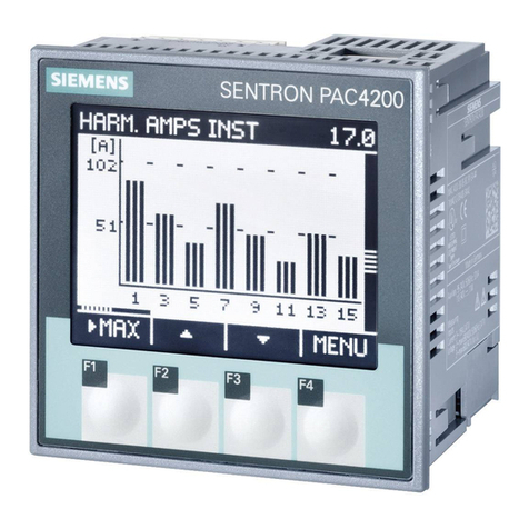
There are 4 dedicated keys labelled as F1, F2, F3, F4. Use
these 4 keys to read meter parameters. Simply press these
keys to read the parameters.
KEY
PRESS ONLINE PAGE DESCRIPTION
Press
“F1”
The fi rst screen: Displays line to neutral voltage of three phase
and average line to neutral voltage.
The second screen: Displays line to line voltage of three phase
and average line to line voltage.
The third screen: Displays total percentage harmonics of line
to neutral voltage of three phase and average line to neutral
voltage.
The fourth screen: Displays total percentage harmonics of line
to line voltage of three phase and average line to line voltage.
Note: 1) For 3 Ø 3 wire system, only second and fourth
screens will be available.
2) For 1 Ø 2 wire system, only fi rst and third screens will
be available.
The fi fth screen: Displays phase current of three phase and
neutral current.
The sixth screen: Displays phase maximum current demand of
three phase and average current.
The seventh screen: Displays total percentage harmonic of
current of three phase and average phase current.
Note: 1) For 3 Ø 3 wire system only fi fth, sixth and seventh
screen will be available. Displays average current
instead of neutral current.
2) For 1 Ø 2 wire instead only fi fth sixth and seventh
screen will be available.
Press
“F2”
The fi rst screen: Displays voltage, current, power factor of fi rst
phase and frequency.
The second screen: Displays voltage, current, power factor of
second phase and frequency.
The third screen: Displays voltage, current, power factor of
third phase and frequency.
The fourth screen: Displays average value of voltage, current
and power factor of three phase and frequency.
Note: 1) For 3 Ø 3 wire system voltage, current, power factor
and frequency will be line to line.
2) For 1 Ø 2 wire system only fi rst screen will be
available.
Press
“F3”
The fi rst screen: Displays power factor of three phase and
average power factor.
The second screen: Displays phase angle of three phase and
Average angle
Note: 1) For 3 ø 3 wire system, only average power factor and
average angle will be available on this screen.
The third screen: Displays active power of three phase and
total active power.
The fourth screen: Displays reactive power of three phase and
total reactive power.
The fi fth screen: Displays apparent power of three phase and
total apparent power.
The sixth screen: Displays active, reactive, apparent power and
power factor of fi rst phase.
The seventh screen: Displays active, reactive, apparent power
and power factor of second phase.
The eighth screen: Displays active, reactive, apparent power
and power factor of third phase.
The ninth screen: Displays total active, reactive, apparent
power and average power factor of three phase.
The tenth screen: Displays maximum active power demand,
reactive power demand and apparent power demand.
The eleventh screen: Displays minimum active power demand
and reactive power demand.
Note: 1) For 3 Ø 3 wire system only ninth, tenth and eleventh
screen will be available.
2) In1Ø 2 wire system only fi rst, second, third, fourth,
fi fth, sixth, ninth, tenth, eleventh screen will be
display
KEY
PRESS ONLINE PAGE DESCRIPTION
Press
“F4”
The fi rst screen: Displays import active energy of fi rst phase.
The second screen: Displays import active energy of second
phase.
The third screen: Displays import active energy of third phase.
The fourth screen: Displays export active energy of fi rst phase.
The fi fth screen: Displays export active energy of second
phase.
The sixth screen: Displays export active energy of third phase.
The seventh screen: Displays total import active energy of
three phase.
The eighth screen: Displays total export active energy of three
phase.
The ninth screen: Displays total net active energy of three
phase.
The tenth Screen: Displays import reactive energy of fi rst
phase.
The eleventh screen: Displays import reactive energy of
second phase.
The twelfth screen: Displays import reactive energy of third
phase.
The thirteenth screen: Displays export reactive energy of fi rst
phase.
The fourteenth screen: Displays export reactive energy of
second phase.
The fi fteenth screen: Displays export reactive energy of third
phase.
The sixteenth screen: Displays total import reactive energy of
three phase.
The seventeenth screen: Displays total export reactive energy
of three phase.
The eighteenth screen: Displays total net reactive energy of
three phase.
The nineteenth screen: Displays apparent energy of fi rst
phase.
The twentieth screen: Displays apparent energy of second
phase.
The twenty fi rst screen: Displays apparent energy of third
phase.
The twenty second screen: Displays total net apparent energy
of three phase.
The twenty third screen: Displays ON hour.
Note: 1) In 3 Ø 3 wire system only seventh, eighth, ninth,
sixteenth, seventeenth, eighteenth, twenty second
and twenty third screens will be available.
2) In 1Ø 2 wire system fi rst, fourth, seventh, eighth,
ninth, tenth, thirteenth, sixteenth, seventeenth,
eighteenth, nineteenth, twenty second and twenty
third screens will be available.
AUTOMATIC / MANUAL MODE DESCRIPTION
Press F4 key for 3 seconds to toggle between Automatic and Manual
mode.
Note: By default unit operates in automatic mode.
In automatic mode online pages scroll automatically at the rate of 5
seconds per page.
In automatic mode when any key is pressed, unit temporarily switches
to manual mode and the appropriate page is displayed, also if any key
is not pressed for 5 sec, unit resumes automatic mode.
SERIAL NUMBER DESCRIPTION
Press F3 key for 5 sec. to display 8 digit serial number only for 5 sec. at
5th line of display
