manuals.online logo
Brands
  1. Home
  2. •
  3. Brands
  4. •
  5. Siemens
  6. •
  7. Switch
  8. •
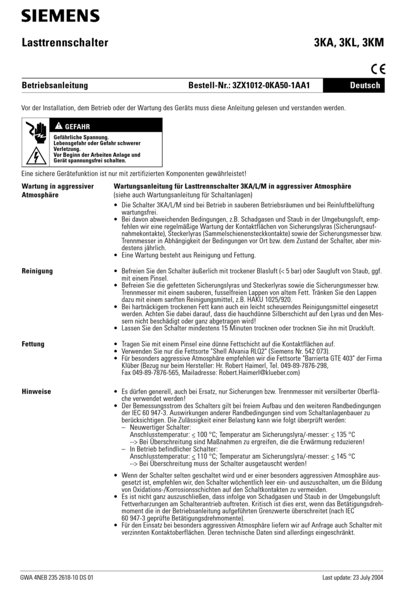
  9. Siemens AP 420/3 IR Service manual

Siemens AP 420/3 IR Service manual

A5E02500167A Seite 1 von 2 page 1 of 2
DS02
GAMMA instabus
AP 420/3 IR Wandsender, 1-fach, titanweiß
AP 420/3 IR wall switch, single, titanium
white
5WG1 420-3AB13
Bedien- und Montageanleitung
Operating and Mounting Instructions
Stand: April 2009
Issued: April 2009
S 450
Bild / Figure 1
A1
A2
A3
A4
Bild / Figure 2
D
Produkt- und Funktionsbeschreibung
Der IR-Wandsender AP 420/3 im Design DELTA style ist in der
Farbe titanweiß mit schwarzer Abdeckung der IR Dioden erhält-
lich.
Zur leitungslosen Ansteuerung von Aktoren sendet der IR-
Wandsender AP 420/3 Infrarot-Signale, die vom IR-
Empfängerdekoder S 450 oder einem Taster mit IR Empfänger-
dekoder aufgenommen und von diesem in entsprechende Bus-
telegramme umgesetzt werden. Dadurch können mit dem IR-
Wandsender z.B. Befehle an Aktoren zum definierten Ein-
/Ausschalten oder zum Dimmen von Leuchten, zum Auf-
/Abfahren oder zum Lamellenverstellen von Jalousien gegeben
werden.
Er wird über zwei Batterien vom Typ Alkaline (LR03/AAA; 1,5V)
mit Strom versorgt.
Hinweis
Die Batterien (Alkaline LR03/AAA, 1,5V) gehören nicht zum Lie-
ferumfang und sind separat zu beschaffen.
Weitere Informationen
http://www.siemens.de/gamma
Anschlussbeispiel
siehe Bild 1
Technische Daten
Spannungsversorgung
zwei Batterien Alkaline LR03/AAA, 1,5V
IR-Sendeeinheit
•Lichtwellenlänge: 890 nm
•Sendefrequenz: 455 kHz
•Senderreichweite:
(direkte optische Verbindung zum Empfänger nötig)
schwarze LED-Abdeckung: ca. 8 m ungerichtet
•einstellbare Kanäle: 1 von 64
Einstellelemente
zur Kanaleinstellung:
Schiebeschalter (befinden sich im Gehäuse), zugänglich nach
Abnahme des Unterteils
Mechanische Daten
•Abmessungen: (B x H x T): 82 x 115 x 21mm
•Gewicht: ca. 80 g (ohne Batterie)
Elektrische Sicherheit
•Schutzart (nach EN 60529): IP 20
Umweltbedingungen
•Klimabeständigkeit: EN 50090-2-2,
•Umgebungstemperatur im Betrieb: - 5 ... + 45 °C
•Lagertemperatur: - 25 ... + 70 °C
•rel. Feuchte (nicht kondensierend): 5 % bis 93 %
Prüfzeichen
CE
Lage- und Funktion der Anzeige- und Bedienelemente
A1 IR-Sendedioden
A2 LED zur Sende- und Batteriekontrolle:
leuchtet bei Betätigung der Wippe;
keine Anzeige beim Drücken der Wippe:
Batterie ersetzen
A3 Beschriftungsfeld
A4 Betätigungswippen
oben drücken (1)= EIN / AUF / HELLER
unten drücken (0)= AUS / AB / DUNKLER
Batteriewechsel
Ein erforderlicher Batteriewechsel wird nach Betätigung einer
Taste durch ein fünf Sekunden andauerndes Blinken der LED sig-
nalisiert.
-Demontage des Wandsenders
-Die leeren Batterien entnehmen und durch neue Batterien
(Alkaline LR03/AAA, 1,5V) ersetzen
-Montage des Wandsenders
-HINWEIS:
Wird innerhalb von zwei Sekunden nach Einlegen der Batte-
rien die Taste unter der SIEMENS Marke fünf Sekunden lang
gedrückt, stellt sich der Wandsender so ein, dass IR Signale
unmittelbar mit dem Tastendruck gesendet werden. Damit
kann in Verbindung mit dem neuen S 450 IR Empfängerde-
koder eine schnellere Reaktion auf Schalt- oder Dimmbefeh-
le erreicht werden. Diese Einstellung ist bis zum nächsten
Batteriewechsel aktiviert.
GB
Product and Applications Description
The AP 420/3 IR wall switch in the design DELTA style is avail-
able with the color titanium white and with a black cover over
the IR diodes.
For wireless control of actuators the AP 420/3 IR wall switch
transmits IR signals that are received by the S 450 IR receiver
decoder or a wall switch with IR receiver-decoder, which trans-
poses them into corresponding bus telegrams. Thus the IR wall
switch can send e.g. commands to actuators for defined on/off
switching or dimming of lamps, or for moving Venetian blinds
up/down or moving their slats.
The IR wall switch is powered by two batteries of type Alkaline
(LR03/AAA; 1,5V).
Note
The batteries (Alkaline LR03/AAA, 1,5V) are not included and
have to be sourced separately.
Additional Information
http://www.siemens.com/gamma
Example of Operation
see figure 1
Technical Specifications
Power supply
two batteries Alkaline LR03/AAA, 1,5V
IR transmission unit
•light wave length: 890 nm
•transmission freq.: 455 kHz
•transmission range:
(the receiver must be within uninterrupted optical reach)
black LED cover: approx. 8 m unfocused
•adjustable channels: 1 of 64
Configuration elements
for channel selection:
slide switches (built in the device), access is possible after re-
moving the bottom part
Physical specifications
•dimensions (W x H x D): 82 x 115 x 21mm
•weight: approx. 80 g (without battery)
Electrical safety
protection (according to EN 60529): IP 20
Environmental specifications
•climatic conditions: EN 50090-2-2
•ambient temperature operating: - 5 ... + 45 °C
•ambient temperature non-op.: - 25 ... + 70 °C
•relative humidity (non-condensing): 5 % to 93 %
Markings
CE
Location and Function of the Display and Operating Elements
A1 IR transmission diodes
A2 LED for transmission and battery observance
flashing on rocker depression;
no display when depressing rocker: replace battery
A3 label field
A4 rocker switch
top depression (1) = ON/UP/BRIGHTER
bottom depression (0) = OFF/DOWN/DARKER
Battery change
The LED flashes for five seconds after a rocker has been de-
pressed if a battery change is required.
-Dismount the wall switch
-Remove the empty batteries and replace these with new bat-
teries (Alkaline LR03/AAA, 1,5V)
-Mount the wall switch
-NOTE:
If within two seconds after inserting the batteries the button
below the SIEMENS logo is pressed for five seconds, the wall
switch is set to send IR signals immediately when a button is
pressed. In conjunction with the new S 450 IR receiver de-
coder swicthing and dimming commands can be issued
faster by the remote. This setting is active until the next bat-
tery change.
Die verbrauchten Batterien sind ent-
sprechend den geltenden Vorschriften
zu entsorgen
The exhausted battery must be dis-
posed of in accordance with the appro-
priate regulations
A5E02500167A Seite 2 von 2 page 2 of 2
DS02
B3
Bild / Figure 3a
Bild / Figure 3b
B10
B
4
Bild / Figure 3c
B11
B12
B13
Bild / Figure 4a
B3
Bild / Figure 4b Bild / Figure 4c
B
2
B
2
B
2
B1
B1
Bild / Figure 5
312 4 56
Bild / Figure 6
Montage und Verdrahtung
Montagehinweise
-Bei der Auswahl des Montageortes ist auf ausreichend freie
Sichtverbindung zwischen den Sendedioden und dem Emp-
fänger zu achten, insbesondere auch, wenn sich zum Betäti-
gen des Senders Personen vor dem Gerät befinden!
-Die Grundplatte des IR-Wandsenders kann wahlweise mit
Schrauben oder mit den beigefügten, doppelseitigen Klebe-
streifen montiert werden.
B1 Wandsender, Seitenansicht
B2 Sicherungsschraube
B3 Halteklammern
B4 Grundplatte, Vorderansicht
B5 Grundplatte, Rückansicht
B6 Horizontale/vertikale Langlöcher
B7 Aussparungen für Klebestreifen
B8 Klebestreifen, doppelseitig
B9 Schutzfolien
B10 Sichtfolie (für Montage auf durchsichtige Materialien)
B11 Typenschild
B12 Schiebeschalter zum Einstellen des IR-Sendekanals
B13 Batteriefach AAA
Montage der Grundplatte (Bild 3)
mit Schrauben
-Durchstoßen Sie mit Hilfe eines Schraubendrehers oder ei-
nem ähnlichen Werkzeug die horizontalen oder vertikalen
Langlöcher (B6) der Grundplatte (B4).
-Befestigen Sie die Grundplatte (B4) mit Schrauben auf einer
UP-Dose (55/60 mm ∅) bzw. mit Dübeln und Schrauben.
mit doppelseitigen Klebestreifen
-Entfernen Sie eine der beiden Schutzfolien (B9) von den
doppelseitigen Klebestreifen (B8) und befestigen Sie diesen
auf der Rückseite der Grundplatte in den entsprechenden
Aussparungen (B7).
-Ziehen Sie nun die restlichen Schutzfolien (B9) ab und drü-
cken Sie die Grundplatte auf einen glatten, staub- und fett-
freien Untergrund oder die Sichtfolie.
-Bei Montage auf durchsichtige Materialien (z.B. Glas) wird
zuerst die beiliegende Sichtfolie (B10) aufgeklebt.
Montage des Wandsenders (Bild 4)
-Legen Sie die Batterien in den Wandsender (B1) ein
-Stellen Sie den gewünschten Sendekanal über die Schiebe-
schalter (B12) auf der Rückseite des Wandsenders (B1) ein.
-Montieren sie das Gerät auf der Grundplatte, indem Sie es
oben in die Grundplatte einhängen und unten in die Halte-
klammern (B3) einrasten.
-Sichern Sie den Wandsender mit Hilfe der beiliegenden Si-
cherungsschraube (B2) gegen Abnehmen.
Demontage des Wandsenders (Bild 5)
-Die Sicherungsschraube (B2) an der Unterseite des Wand-
senders (B1) lösen.
-Schraubendreher unterhalb des Doms für die Sicherungs-
schraube ansetzen, den Wandsender durch Hochschwenken
des Schraubendrehers von der Grundplatte lösen und den
Wandsender abheben.
Sendekanal einstellen
Der IR-Wandsender AP420/3 nutzt einen Kanal zum Senden der
IR-Signale. Dafür stehen dem Gerät 64 Kanäle zur Auswahl.
Der Sendekanal wird mit den Schiebeschaltern 1 bis 6 (Bild 6),
die sich auf der Rückseite des Gerätes (B12) befinden, einge-
stellt.
Kanalzuordnung entsprechend der Schalterstellungen
Schiebeschalter
Kanal 1 2 3 4 5 6
0 0 0 0 0 0 0
1 0 0 0 0 0 1
2 0 0 0 0 1 0
3 0 0 0 0 1 1
4 0 0 0 1 0 0
5 0 0 0 1 0 1
6 0 0 0 1 1 0
7 0 0 0 1 1 1
8 0 0 1 0 0 0
:
61 1 1 1 1 0 1
62 1 1 1 1 1 0
63 1 1 1 1 1 1
Allgemeine Hinweise
•Die Bedienungsanleitung ist dem Kunden auszuhändigen.
•Ein defektes Gerät ist an die zuständige Geschäftsstelle der
Siemens AG zu senden.
•Bei zusätzlichen Fragen zum Produkt wenden Sie sich bitte
an unseren Technical Support:
℡+49 (0) 180 50 50-222
(0,14 €/Minute aus dem deutschen Festnetz, abweichende Mo-
bilfunkpreise möglich)
+49 (0) 180 50 50-223
E-Mail: support.automation@siemens.com
www.siemens.de/automation/support-request
Location and Function of the Display and Operating Elements
Mounting notes
-Take care that the line of sight from the transmission diodes
to the receiver is sufficiently free. Especially, if persons are
standing in front of the device in order to use it.
-The base plate of the IR-transmitter can be mounted with
screws or optionally with the included double faced adhe-
sive film.
B1 IR wall switch, side view
B2 latching screw
B3 interlocking clamps
B4 base plate, front view
B5 base plate, rear view
B6 horizontal/vertical long slots
B7 recesses for adhesive tape
B8 double faced adhesive tape
B9 protective films
B10 Non-transparent foil (for mounting on transparent
material)
B11 Label
B12 Slide switches for selection of the IR transmission
channel
B13 battery compartment AAA
Mounting of the base plate (Figure 3)
with screws
-Pierce the horizontal or vertical holes (B6) of the base panel
(B4) with a screw-driver or another suitable tool.
-Attach the base panel (B4) with screws respectively with
dowels and screws.
with double faced adhesive tape
-Remove one of the protection films (B9) from the double-
faced adhesive tape (B8) and stick the tape in the recesses
(B7) on the device's back side.
-Strip off the remaining protection films (B9) and push
the base panel onto a smooth, dustless and greaseless foun-
dation or the non-transparent foil.
-When installing on transparent material (e.g. glass) stick the
transparent foil (B10) on the transparent material.
Mounting the IR wall switch (Figure 4)
-Insert the batteries into the wall switch (B1)
-Select the desired IR transmission channel with the sliding
switches (B12) on the rear side of the wall switch (B1).
-Hang the device onto the base panel with its upper side and
click it into place at the retaining clamps with its bottom side
to attach the device on the base panel.
-Secure the wall switch with the included latching screw (B2)
against unintentional dismounting.
Dismounting the IR wall switch (Figure 5)
-Unscrew the latching screw (B2) on the bottom side of the
wall switch (B1).
-Insert the screw driver below the screw hole for the latching
screw, detach the wall switch from the base plate by swivel-
ing the screw driver up and lift the wall switch from the base
plate.
Select IR transmission channel
The AP 420/3 IR wall switch uses one channel for transmitting
the IR signals. A maximum of 64 channels are available.
The transmission channel is selected with the sliding switches 1
to 6 (figure 6) that are on the rear side of the device (B12).
Channel assignment dependent on the sliding switch positions
Sliding switch
Channel 1 2 3 4 5 6
0 0 0 0 0 0 0
1 0 0 0 0 0 1
2 0 0 0 0 1 0
3 0 0 0 0 1 1
4 0 0 0 1 0 0
5 0 0 0 1 0 1
6 0 0 0 1 1 0
7 0 0 0 1 1 1
8 0 0 1 0 0 0
:
61 1 1 1 1 0 1
62 1 1 1 1 1 0
63 1 1 1 1 1 1
General Notes
•The operating instructions must be handed over to the client.
•Any faulty devices should be returned to the local Siemens
office.
•If you have further questions concerning the product please
contact our technical support:
℡+49 (0) 180 50 50-222
(0,14 €/min. from the German landline network, deviating mo-
bile communications prices are possible)
+49 (0) 180 50 50-223
E-Mail: support.automation@siemens.com
www.siemens.com/automation/support-request
This manual suits for next models

1

Other Siemens Switch manuals

Siemens Pointek CLS200 Instruction manual

Siemens

Siemens Pointek CLS200 Instruction manual

Siemens SITRANS LVL200E User manual

Siemens

Siemens SITRANS LVL200E User manual

Siemens 3TS11 Series User manual

Siemens

Siemens 3TS11 Series User manual

Siemens Sirius 3RT105 Series User manual

Siemens

Siemens Sirius 3RT105 Series User manual

Siemens 3NJ621 User manual

Siemens

Siemens 3NJ621 User manual

Siemens 3VA9978-0AB2 User manual

Siemens

Siemens 3VA9978-0AB2 User manual

Siemens SCALANCE X414-3E Administrator guide

Siemens

Siemens SCALANCE X414-3E Administrator guide

Siemens ASC77.1E User manual

Siemens

Siemens ASC77.1E User manual

Siemens SITRANS LVL100 User manual

Siemens

Siemens SITRANS LVL100 User manual

Siemens SIMATIC NET RUGGEDCOM RS920L User manual

Siemens

Siemens SIMATIC NET RUGGEDCOM RS920L User manual

Siemens SIMATIC NET RUGGEDCOM RS940G User manual

Siemens

Siemens SIMATIC NET RUGGEDCOM RS940G User manual

Siemens 3KF2 F Series User manual

Siemens

Siemens 3KF2 F Series User manual

Siemens SIRIUS 3SE2283 GA4 Series User manual

Siemens

Siemens SIRIUS 3SE2283 GA4 Series User manual

Siemens FDM243H User manual

Siemens

Siemens FDM243H User manual

Siemens CNFS Series User manual

Siemens

Siemens CNFS Series User manual

Siemens RUGGEDCOM RSG2100F User manual

Siemens

Siemens RUGGEDCOM RSG2100F User manual

Siemens SCALANCE X-300 Instruction sheet

Siemens

Siemens SCALANCE X-300 Instruction sheet

Siemens SIRIUS 3SE7310-1AE Series User manual

Siemens

Siemens SIRIUS 3SE7310-1AE Series User manual

Siemens SIMATIC NET RUGGEDCOM RS950G User manual

Siemens

Siemens SIMATIC NET RUGGEDCOM RS950G User manual

Siemens SIMATIC NET RUGGEDCOM RX1501 User manual

Siemens

Siemens SIMATIC NET RUGGEDCOM RX1501 User manual

Siemens SIRIUS 3SE54 Series User manual

Siemens

Siemens SIRIUS 3SE54 Series User manual

Siemens 5ST3062 User manual

Siemens

Siemens 5ST3062 User manual

Siemens RUGGEDCOM RP110 User manual

Siemens

Siemens RUGGEDCOM RP110 User manual

Siemens 5WG1 233-2AB01 User manual

Siemens

Siemens 5WG1 233-2AB01 User manual

Popular Switch manuals by other brands

Cisco Catalyst WS-X6704-10GE datasheet

Cisco

Cisco Catalyst WS-X6704-10GE datasheet

DH Instruments MFC SWITCHBOX user manual

DH Instruments

DH Instruments MFC SWITCHBOX user manual

Nextav cloudhub x100 Quick installation guide

Nextav

Nextav cloudhub x100 Quick installation guide

Pilz PSEN ma1.3a/b-20 operating instructions

Pilz

Pilz PSEN ma1.3a/b-20 operating instructions

H3C S5800-EI Series installation guide

H3C

H3C S5800-EI Series installation guide

Comtrend Corporation ES-7201PoE user manual

Comtrend Corporation

Comtrend Corporation ES-7201PoE user manual

Lenovo ThinkSystem NE1032T installation guide

Lenovo

Lenovo ThinkSystem NE1032T installation guide

FS S3400-24T4SP quick start guide

FS

FS S3400-24T4SP quick start guide

Cisco SR224R datasheet

Cisco

Cisco SR224R datasheet

IOGear MiniView G-CS12 owner's manual

IOGear

IOGear MiniView G-CS12 owner's manual

Festo SMT-8M-A-...-24V-E Series Translation of the original instructions

Festo

Festo SMT-8M-A-...-24V-E Series Translation of the original instructions

Juniper QFX5220-32CD quick start guide

Juniper

Juniper QFX5220-32CD quick start guide

Roland V-160HD Reference manual

Roland

Roland V-160HD Reference manual

Teltone M-392 product manual

Teltone

Teltone M-392 product manual

SMC Networks TigerSwitch SMC8028L2 Specifications

SMC Networks

SMC Networks TigerSwitch SMC8028L2 Specifications

Weco ESS LV-HUB XP manual

Weco

Weco ESS LV-HUB XP manual

Huawei Quidway S5624F Specifications

Huawei

Huawei Quidway S5624F Specifications

Hawking GS400T Specifications

Hawking

Hawking GS400T Specifications

manuals.online logo
manuals.online logoBrands
  • About & Mission
  • Contact us
  • Privacy Policy
  • Terms and Conditions

Copyright 2025 Manuals.Online. All Rights Reserved.