RS PRO RS-960 User manual

Africa
RS Components SA
P.O. Box 12182,
Vorna Valley, 1686
20 Indianapolis Street,
Kyalami Business Park,
Kyalami, Midrand
South Africa
www.rs-components.com
Asia
RS Components Ltd.
Suite 1601, Level 16,Tower 1,
Kowloon Commerce Centre,
51 Kwai Cheong Road,
Kwai Chung, Hong Kong
www.rs-components.com
China
RS Components Ltd.
Suite 23 A-C
East Sea Business Centre
Phase 2
No. 618Yan'an Eastern Road
Shanghai, 200001
China
www.rs-components.com
Europe
RS Components Ltd.
PO Box 99, Corby,
Northants.
NN17 9RS
United Kingdom
www.rs-components.com
Japan
RS Components Ltd.
WestTower (12th Floor),
Yokohama Business Park,
134 Godocho, Hodogaya,
Yokohama, Kanagawa 240-0005
Japan
www.rs-components.com
U.S.A
Allied Electronics
7151 Jack Newell Blvd. S.
Fort Worth,
Texas 76118
U.S.A.
www.alliedelec.com
South America
RS Componentes Limitada
Av. Pdte. Eduardo Frei M. 6001-71
Centro Empresas El Cortijo
Conchali, Santiago, Chile
www.rs-components.com
Instruction Manual
RS-960
Stock No: 146-9085
True RMS Compact Digital Multimeter
EN

1
1. Introduction
This meter measures AC/DC Voltage, AC/DC Current, Resistance, Capacitance, Frequency
(electrical ), Diode Test, and Continuity . It features a waterproof, rugged design for heavy
duty use. Proper use and care of this meter will provide many years of reliable service.
Safety
This symbol adjacent to another symbol, terminal or operating device indicates that the
operator must refer to an explanation in the Operating Instructions to avoid personal injury or
damage to the meter
This WARNING symbol indicates a potentially hazardous situation, which if not avoided, could
result in death or serious injury.
This CAUTION symbol indicates a potentially hazardous situation, which if not avoided, may
result damage to the product.
WARNING
CAUTION
22/11/2017 Version No.001
True RMS Compact Digital Multimeter / English
This symbol advises the user that the terminal(s) so marked must not be
connected to a circuit point at which the voltage with respect to earth
ground exceeds (in this case) 600VAC or VDC.
This symbol adjacent to one or more terminals identifies them as being
associated with ranges that may, in normal use, be subjected to particularly
hazardous voltages. For maximum safety, the meter and its test leads should
not be handled when these terminals are energized.
This symbol indicates that a device is protected throughout by double
insulation or reinforced insulation.

2 3
2. PER IEC1010 OVERVOLTAGE INSTALLATION CATEGORY
OVERVOLTAGE CATEGORY I
Equipment of OVERVOLTAGE CATEGORY I is equipment for connection to circuits in
which measures are taken to limit the transient overvoltages to an appropriate low level.
Note – Examples include protected electronic circuits.
OVERVOLTAGE CATEGORY II
Equipment of OVERVOLTAGE CATEGORY II is energy-consuming equipment to be supplied
from the fixed installation.
Note – Examples include household, office, and laboratory appliances.
OVERVOLTAGE CATEGORY III
Equipment of OVERVOLTAGE CATEGORY III is equipment in fixed installations.
Note – Examples include switches in the fixed installation and some equipment for
industrial use with permanent connection to the fixed installation.
OVERVOLTAGE CATEGORY IV
Equipment of OVERVOLTAGE CATEGORY IV is for use at the origin of the installation.
Note – Examples include electricity meters and primary over-current protection equipment
3. SAFETY INSTRUCTIONS
This meter has been designed for safe use, but must be operated with caution.
The rules listed below must be carefully followed for safe operation.
3.1 NEVER apply voltage or current to the meter that exceeds the specied maximum:
Input Protection Limits
Function Maximum Input
VDC or VAC 600V DC/AC rms
mA AC/DC 500mA 600V fast acting fuse
A AC/DC 10A 600V fast acting fuse
Frequency, Resistance, Capacitance, Diode
Test, Continuity 300V DC/AC rms
Surge Protection: 6kV peak per IEC 61010
3.2 USE EXTREME CAUTION when working with high voltages.
3.3 DO NOT measure voltage if the voltage on the "COM" input jack exceeds 600V above
earth ground.
3.4 NEVER connect the meter leads across a voltage source while the function switch is in
the current, resistance, or diode mode. Doing so can damage the meter.
3.5 ALWAYS discharge filter capacitors in power supplies and disconnect the power when
making resistance or diode tests.
3.6 ALWAYS turn off the power and disconnect the test leads before opening the covers to
replace the fuse or batteries.
3.7 NEVER operate the meter unless the back cover and the battery and fuse covers are in
place and fastened securely.
3.8 If the equipment is used in a manner not specified by the manufacturer, the protection
provided by the equipment may be impaired.
4. Controls and Jacks
1. Battery Cover
2. 4,000 counts LCD Negativity display
3. RANGE button
4. MAX/MIN button
5. Mode button
6. HOLD and Flashlight button
7. Function switch
8. COM input jack
9. 10A input jacks
10. Positive,mA, µA input jack
Note: Tilt stand and battery compartment are on rear of unit.
22/11/2017 Version No.00122/11/2017 Version No.001
True RMS Compact Digital Multimeter / EnglishTrue RMS Compact Digital Multimeter / English

4 5
5. Symbols and Annunciators
Auto power off
Continuity
Diode test
Battery status
nnano (10-9) (capacitance)
µmicro (10-6) (amps, cap)
mmilli (10-3) (volts, amps)
AAmps
kkilo (103) (ohms)
FFarads (capacitance)
Mmega (106) (ohms)
ΩOhms
Hz Hertz (frequency)
VVolts
%Percent (duty ratio)
1. ALWAYS turn the function switch to the OFF position when the meter is not in use.
2. If “OL” appears in the display during a measurement, the value exceeds the range you have
selected. Change to a higher range.
DC VOLTAGE MEASUREMENTS
1. Set the function switch to the green VDC position.
2. Insert the black test lead banana plug into the negative COM jack.
Insert the red test lead banana plug into the positive V jack.
3. Touch the black test probe tip to the negative side of the circuit.
Touch the red test probe tip to the positive side of the circuit.
4. Read the voltage in the display.
WARNING: Risk of Electrocution. The probe tips may not be long enough to contact the
live parts inside some 240V outlets for appliances because the contacts are recessed
deep in the outlets. As a result, the reading may show 0 volts when the outlet actually
has voltage on it. Make sure the probe tips are touching the metal contacts inside the
outlet before assuming that no voltage is present.
CAUTION: Do not measure AC voltages if a motor on the circuit is being switched ON or
OFF. Large voltage surges may occur that can damage the meter.
1. Set the function switch to the green VAC/Hz/% position.
2. Insert the black test lead banana plug into the negative COM jack.
Insert red test lead banana plug into the positive V jack.
3. Touch the black test probe tip to the neutral side of the circuit.
Touch the red test probe tip to the “hot” side of the circuit.
4. Read the voltage in the display.
5. Press the HZ/% button to indicate “Hz”.
6. Read the frequency in the display.
7. Press the Hz/% button again to indicate “%”.
8. Read the % of duty cycle in the display.
CAUTION: Do not make 20A current measurements for longer than 30 seconds.
Exceeding 30 seconds may cause damage to the meter and/or the test leads.
1. Insert the black test lead banana plug into the negative COM jack.
2. For current measurements up to 6000µA DC, set the function switch to the yellow µA
position and insert the red test lead banana plug into the µA/mA jack.
3. For current measurements up to 600mA DC, set the function switch to the yellow mA
position and insert the red test lead banana plug into the µA/mA jack.
4. For current measurements up to 20A DC, set the function switch to the yellow 10A/HZ/%
position and insert the red test lead banana plug into the 10A jack.
5. Press the MODE button to indicate “DC” on the display.
6. Remove power from the circuit under test, then open up the circuit at the point where you
wish to measure current.
AC Alternating current
AUTO Autoranging
DC Direct current
HOLD Display hold
MAX Maximum
MIN Minimum
Operating Instructions
WARNING: Risk of electrocution. High-voltage circuits, both AC and DC, are very
dangerous and should be measured with great care.
CAUTION: Do not measure DC voltages if a motor on the circuit is being switched ON or
OFF. Large voltage surges may occur that can damage the meter.
AC VOLTAGE (FREQUENCY, DUTY CYCLE) MEASUREMENTS
DC CURRENT MEASUREMENTS
22/11/2017 Version No.00122/11/2017 Version No.001
True RMS Compact Digital Multimeter / EnglishTrue RMS Compact Digital Multimeter / English

6 7
7. Touch the black test probe tip to the negative side of the circuit. Touch the red test probe
tip to the positive side of the circuit.
8. Apply power to the circuit.
9. Read the current in the display.
1. Insert the black test lead banana plug into the negative COM jack.
2. For current measurements up to 6000µA AC, set the function switch to the yellow µA
position and insert the red test lead banana plug into the µA/mA jack.
3. For current measurements up to 600mA AC, set the function switch to the yellow mA
position and insert the red test lead banana plug into the µA/mA jack.
4. For current measurements up to 20A AC, set the function switch to the yellow 10A/HZ/%
position and insert the red test lead banana plug into the 10A jack.
5. Press the MODE button to indicate “AC” on the display.
6. Remove power from the circuit under test, then open up the circuit at the point where you
wish to measure current.
7. Touch the black test probe tip to the neutral side of the circuit. Touch the red test probe tip
to the “hot” side of the circuit.
8. Apply power to the circuit.
9. Read the current in the display.
1. Set the function switch to the green Ω CAP position.
Insert the black test lead banana plug into the negative COM jack.
Insert the red test lead banana plug into the positive Ω jack.
2. Press the MODE button to indicate “Ω” on the display.
3. Touch the test probe tips across the circuit or part under test. It is best to disconnect one
side of the part under test so the rest of the circuit will not interfere with the resistance
reading.
4. Read the resistance in the display.
WARNING: To avoid electric shock, never measure continuity on circuits or wires that
have voltage on them.
1. Set the function switch to the green Ω CAP position.
2. Insert the black lead banana plug into the negative COM jack.
Insert the red test lead banana plug into the positive Ω jack.
3. Press the MODE button to indicate“ ”and “Ω” on the display
4. Touch the test probe tips to the circuit or wire you wish to check.
5. If the resistance is less than approximately 50Ω, the audible signal will sound.
If the circuit is open, the display will indicate “OL”.
DIODE TEST
1. Set the function switch to the green Ω CAP position.
2. Insert the black test lead banana plug into the negative COM jack and the red test lead
banana plug into the positive V jack.
3. Press the MODE button to indicate and V on the display.
4. Touch the test probes to the diode under test. Forward voltage will typically indicate 0.400
to 0.700V. Reverse voltage will indicate “OL”. Shorted devices will indicate near 0V and an
open device will indicate “OL” in both polarities.
CAPACITANCE MEASUREMENTS
1. Set the rotary function switch to the green Ω CAP position.
2. Insert the black test lead banana plug into the negative COM jack.
Insert the red test lead banana plug into the positive V jack.
3. Press the MODE button to indicate “nF” on the display.
4. Touch the test leads to the capacitor to be tested.
5. The test may take up to 3 minutes or more for large capacitors to charge. Wait until the
readings settle before ending the test.
6. Read the capacitance value in the display
AC CURRENT (FREQUENCY, DUTY CYCLE) MEASUREMENTS
CAUTION: Do not make 20A current measurements for longer than 30 seconds.
Exceeding 30 seconds may cause damage to the meter and/or the test leads.
RESISTANCE MEASUREMENTS
WARNING: To avoid electric shock, disconnect power to the unit under test and
discharge all capacitors before taking any resistance measurements. Remove the
batteries and unplug the line cords.
CONTINUITY CHECK
WARNING: To avoid electric shock, disconnect power to the unit under test and
discharge all capacitors before taking any capacitance measurements. Remove the
batteries and unplug the line cords.
22/11/2017 Version No.00122/11/2017 Version No.001
True RMS Compact Digital Multimeter / EnglishTrue RMS Compact Digital Multimeter / English

8 9
6. AUTORANGING/MANUAL RANGE SELECTION
When the meter is first turned on, it automatically goes into Autoranging. This automatically
selects the best range for the measurements being made and is generally the best mode for
most measurements. For measurement situations requiring that a range be manually selected,
perform the following:
1. Press the RANGE key. The “AUTO” display indicator will turn off.
2. Press the RANGE key to step through the available ranges until you select the range you want.
3. To exit the Manual Ranging mode and return to Autoranging, press and hold the RANGE
key for 2 seconds.
Note: Manual ranging does not apply for the Capacitance and Frequency functions.
MAX/MIN
Note: When using the MAX/MIN function in Autoranging mode, the meter will “lock” into
the range that is displayed on the LCD when MAX/MIN is activated. If a MAX/Min reading
exceeds that range, an “OL” will be displayed. Select the desired range BEFORE entering
MAX/MIN mode.
1. Press the MAX/MIN key to activate the MAX/MIN recording mode. The display icon
"MAX" will appear. The meter will display and hold the maximum reading and will update
only when a new “max” occurs.
2. Press the MAX/MIN key again and the display icon "MIN" will appear. The meter will
display and hold the minimum reading and will update only when a new “min” occurs.
3. To exit MAX/MIN mode press and hold the MAX/MIN key for 2 seconds.
DISPLAY BACKLIGHT
Positive Display and Backlight on when unit is turned on
MODE
Press MODE key the selection of double measured functions which are present at display
is possible. In particular this key is active in V/ / CAP/ Ω position to select among
resistance test, diode test, continuity test and capacitance test, and in current position to
select between AC or DC current measurements.
HOLD/ FLASH LIGHT
The hold function freezes the reading in the display. Press the HOLD key momentarily to
activate or to exit the HOLD function.
Press the HOLD key for >1 second to turn on or off the FLASH light function.The flash light
and will automatically power OFF after 5 minutes of inactivity.
AUTO POWER OFF
The auto off feature will turn the meter off after 15 minutes. To disable the auto power off
feature, hold down the MODE button and turn the meter on.
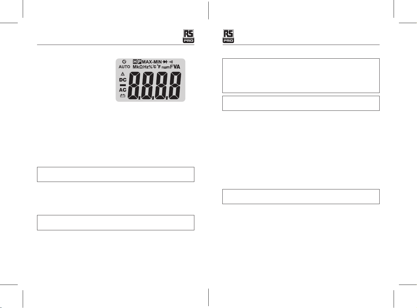
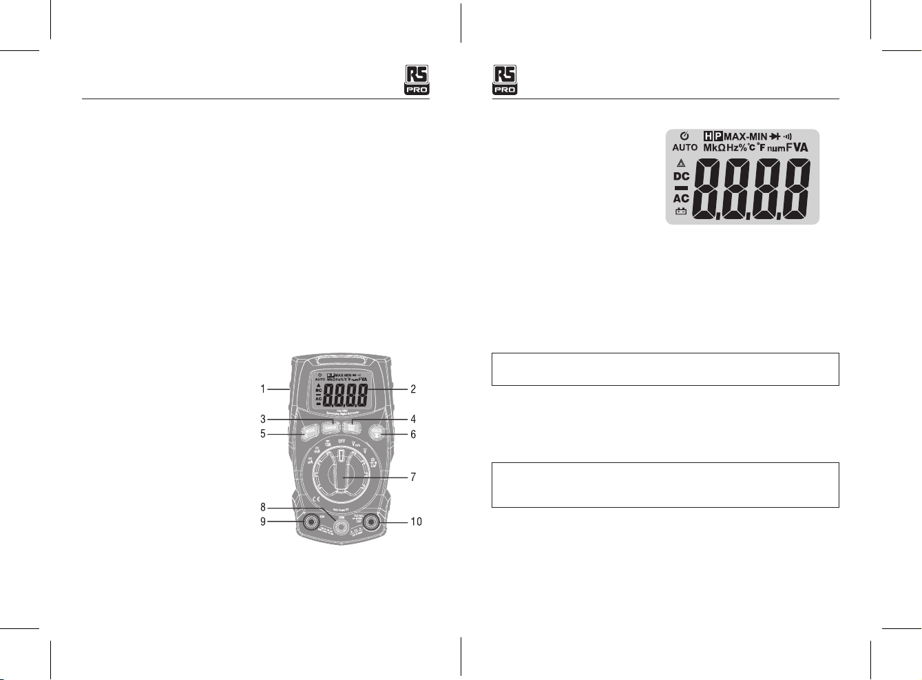
LOW BATTERY INDICATION
The icon will appear in the lower left conner of the display when the battery voltage
becomes low. Replace the battery when this appears.
WARNING: To avoid electric shock, do not operate your meter until the battery and fuse
covers are in place and fastened securely.
This MultiMeter is designed to provide years of dependable service, if the following care
instructions are performed:
1. KEEP THE METER DRY. If it gets wet, wipe it off.
2. USE AND STORE THE METER IN NORMAL TEMPERATURES. Temperature extremes can
shorten the life of the electronic parts and distort or melt plastic parts.
3. HANDLE THE METER GENTLY AND CAREFULLY. Dropping it can damage the electronic
parts or the case.
4. KEEP THE METER CLEAN. Wipe the case occasionally with a damp cloth. DO NOT use
chemicals, cleaning solvents, or detergents.
5. USE ONLY FRESH BATTERIES OF THE RECOMMENDED SIZE AND TYPE. Remove old or
weak batteries so they do not leak and damage the unit.
6. IF THE METER IS TO BE STORED FOR A LONG PERIOD OF TIME, the batteries should be
removed to prevent damage to the unit.
WARNING: To avoid electric shock, disconnect the test leads from any source of voltage
before removing the battery cover.
1. Turn power off and disconnect the test leads from the meter.
2. Open the rear battery cover by removing the screw using a Phillips head screwdriver.
3. Insert the battery into battery holder, observing the correct polarity.
4. Put the battery cover back in place. Secure with the screw.
22/11/2017 Version No.00122/11/2017 Version No.001
True RMS Compact Digital Multimeter/EnglishTrue RMS Compact Digital Multimeter/English
7. Maintenance
WARNING: To avoid electric shock, disconnect the test leads from any source of voltage
before removing the back cover or the battery or fuse covers.
BATTERY INSTALLATION
22/11/2017 Version No.00122/11/2017 Version No.001
True RMS Compact Digital Multimeter / EnglishTrue RMS Compact Digital Multimeter / English

10 11
WARNING: To avoid electric shock, do not operate the meter until the battery cover is
in place and fastened securely.
NOTE: If your meter does not work properly, check the fuses and batteries to make sure that
they are still good and that they are properly inserted.
WARNING: To avoid electric shock, disconnect the test leads from any source of voltage
before removing the fuse cover.
1. Disconnect the test leads from the meter.
2. Remove the battery cover.
3. Gently remove the old fuse and install the new fuse into the holder.
4. Always use a fuse of the proper size and value (0.5A/600V fast blow for the 600mA range,
10A/600V fast blow for the 20A range.
5. Replace and secure the rear cover, battery and battery cover.
WARNING: To avoid electric shock, do not operate your meter until the fuse cover is in
place and fastened securely.
Function Range Resolution Accuracy
DC Voltage
400mV 0.1mV ±(1.0%reading + 5digits)
4V 0.001V
±(1.0%reading + 3digits)
40V 0.01V
400V 0.1V
600V 1V
AC Voltage
50Hz to 60Hz
4V 0.001V
±(1.2%reading + 3 digits)
40V 0.01V
400V 0.1V
600V 1V
All AC voltage ranges are specified from 5% of range to 100% of range
DC Current
400µA 0.1µA ±(1.0%reading + 3digits)
4000µA 1µA
40mA 0.01mA
400mA 0.1mA
Function Range Resolution Accuracy
Resistance
400Ω 0.1kΩ
±(1.5%reading + 5 digits)
4kΩ 0.001kΩ
40kΩ 0.01kΩ
400kΩ 0.1kΩ
4MΩ 0.001MΩ
40MΩ 0.01MΩ ±(2.5%reading + 20 digits)
Capacitance
40nF 0.01nF ±(4.5%reading + 10 digits)
400nF 0.1nF
4µF 0.001µF
±(3.0%reading + 5 digits)40µF 0.01µF
400µF 0.1µF
4000µF 1µF ±(5%reading + 5 digits)
Frequency
(electrical)
10.00-10KHz 0.01Hz ±(1.2% reading)
Sensitivity: 15Vrms
Duty Cycle 0.1 to 99.9% 0.1% ±(1.2% reading + 2 digits)
Pulse width: 100µs - 100ms, Frequency: 5Hz to 150kHz
8. Specications
DC Current
4A 0.001A ±(1.2%reading + 3 digits)
10A 0.01A
(20A: 30 sec max with reduced accuracy)
AC Current
50Hz to 60Hz
400µA 0.1µA
±(1.2%reading + 3 digits)
4000µA 1µA
40mA 0.01mA
400mA 0.1mA
4A 0.001A ±(1.8%reading + 5 digits)
10A 0.01A
(20A: 30 sec max with reduced accuracy)
All AC voltage ranges are specified from 5% of range to 100% of range
NOTE: Accuracy is stated at 65oF to 83oF (18oC to 28oC) and less than 75% RH.
Note: Accuracy specifications consist of two elements:
• (% reading) – This is the accuracy of the measurement circuit.
• (+ digits) – This is the accuracy of the analog to digital converter.
REPLACING THE FUSES
22/11/2017 Version No.00122/11/2017 Version No.001
True RMS Compact Digital Multimeter / EnglishTrue RMS Compact Digital Multimeter / English

12
Manuel d'instructions
RS-960
No d'inventaire: 146-9085
Multimètre numérique compact True RMS
FR
Enclosure Double molded
Shock (Drop Test) 6.5 feet (2 meters)
Diode Test Test current of 1.5 mA maximum, open circuit voltage 3V DC typical
Continuity Check Audible signal will sound if the resistance is less than 50Ω (approx.),
test current <0.35mA
Temperature Sensor Requires type K thermocouple
Input Impedance >10MΩ VDC & >10MΩ VAC
AC Response TRMS
ACV Bandwidth 50/60HZ(ALL WAVE) 45Hz to 1000Hz(SINE WAVE)
Crest Factor ≤3 at full scale up to 300V, decreasing linearly to ≤1.5 at 600V
Display 4,000 counts Positive Display
Overrange indication “OL” is displayed
Auto Power Off 15 minutes (approximately) with disable feature
Polarity Automatic (no indication for positive); Minus (-) sign for negative
Measurement Rate 3 times per second, nominal
Low Battery Indication “ ” is displayed if battery voltage drops below operating voltage
Battery 1.5V AAA * 2 battery
Fuses mA, µA ranges; 0.5A 600V ceramic fast blow A range;
10A/600V ceramic fast blow
Operating Temperature 41oF to 104oF (5oC to 40oC)
Storage Temperature -4oF to 140oF (-20oC to 60oC)
Operating Humidity Max 80% up to 87oF (31oC) decreasing linearly to 50% at 104oF
(40oC)
Storage Humidity <80%
Operating Altitude 7000ft. (2000meters) maximum.
Weight 0.753lb (342g) (includes holster).
Size (182 x 82 x 59mm) (includes holster)
Safety This meter is intended for origin of installation use and protected,
against the users, by double insulation per EN61010-1 and IEC61010-1
2nd Edition (2001) to Category III 600V and Category II 1000V;
Pollution Degree 2. The meter also meets UL 61010-1, 2nd Edition
(2004), CAN/CSA C22.2 No. 61010-1 2nd Edition (2004), and UL
61010B-2-031, 1st Edition (2003)
22/11/2017 Version No.001
True RMS Compact Digital Multimeter / English

14 15
1. Introduction
Ce compteur mesure la tension AC / DC, le courant AC / DC, la résistance, la capacité, la
fréquence (électrique), le test de diode et la continuité. Il dispose d'un design étanche et
robuste pour une utilisation intensive. L'utilisation et l'entretien appropriés de ce compteur
fourniront de nombreuses années de service fiable.
ATTENTION
MISE EN GARDE
Ce symbole indique à l'utilisateur que le (s) terminal (s) ainsi marqué (s) ne
doit pas être connecté à un point de circuit auquel la tension par rapport à la
terre qui dépasse (dans ce cas) 600VAC ou VDC.
Ce symbole adjacent à un ou plusieurs terminaux les identifie comme étant
associés à des gammes qui peuvent, en utilisation normale, être soumises à
des tensions particulièrement dangereuses. Pour une sécurité maximale, le
multimètre et ses fils ne doivent pas être manipulés lorsque ces bornes sont
sous tension.
Ce symbole indique qu'un dispositif est entièrement protégé par une double
isolation ou une isolation renforcée.
Sécurité
Ce symbole adjacent à un autre symbole, terminal ou dispositif de commande indique que
l'opérateur doit se reporter à une explication dans les instructions pour éviter des blessures
corporelles ou des dommages au compteur.
Ce symbole d’AVERTISSEMENT indique une situation potentiellement dangereuse , si elle n'est
pas évitée, pourrait entraîner la mort ou des blessures graves.
Ce symbole ATTENTION indique une situation potentiellement dangereuse , si elle n'est pas
évitée, peut endommager le produit.
2.TYPE D'INSTALLATION DE SURTENSION CEI 1010 ET LA
CATÉGORIE DE SURTENSION I
L'équipement de la CATÉGORIE DE SURTENSION I est un équipement de connexion à des
circuits dans lequel des mesures sont prises pour limiter les surtensions transitoires à un
niveau bas approprié.
Remarque - Les exemples incluent les circuits électroniques protégés.
CATÉGORIE DE SURTENSION II
L'équipement de SURVOLTAGE CATÉGORIE II est un équipement consommateur d'énergie qui
doit être fourni par l'installation fixe.
Remarque - Les exemples comprennent les appareils ménagers, de bureau et de laboratoire.
CATÉGORIE DE SURTENSION III
L'équipement de la CATÉGORIE DE SURTENSION III est l'équipement dans les installations
fixes.
Remarque - Les exemples incluent les commutateurs dans l'installation fixe et certains
équipements à usage industriel avec connexion permanente à l'installation fixe.
CATÉGORIE DE SURTENSION IV
L'équipement de SURVOLTAGE CATÉGORIE IV est à utiliser à l'origine de l'installation.
Remarque - Les exemples comprennent les compteurs d'électricité et l'équipement de
protection primaire contre les surintensités.
3. INSTRUCTIONS DE SECURITE
Ce compteur a été conçu pour une utilisation sûre, mais doit être utilisé avec prudence.
Les règles énumérées ci-dessous doivent être soigneusement suivies pour un fonctionnement sûr.
3.1 NE JAMAIS appliquer de tension ou de courant au compteur qui dépasse le maximum
spécifié:
Limites de la protection d'entrée
Fonction Maximum d'entrée
VDC or VAC 600V DC/AC rms
mA AC/DC Fusible à l’action rapide 500mA 600V
A AC/DC Fusible à l’action rapide 10A 600V
Fréquence, résistance, capacité, test de
diode, continuité 300V DC/AC rms
Protection contre les surtensions: pic de 6 kV selon IEC 61010
22/11/2017 Version No.00122/11/2017 Version No.001
Multimètre numérique compactTrue RMS / Francais

16 17
3.2 UTILISER EXTREMEMENT AVEC ATTENTION lorsque vous travaillez avec des
tensions élevées.
3.3 Ne pas mesurer si la tension sur la prise d'entrée "COM" dépasse 600V au-dessus de la terre.
3.4 NE JAMAIS raccorder les fils du multimètre à une source de tension lorsque le
commutateur est en mode courant, résistance ou diode. Cela pourrait endommager le
compteur.
3.5 Décharger toujours les condensateurs de filtrage dans les alimentations et couper
l'alimentation lors des tests de résistance ou de diode.
3.6 Couper toujours l'alimentation et débrancher les fils avant d'ouvrir les couvercles pour
remplacer les fusibles.
3.7 NE JAMAIS faire fonctionner le compteur à moins que le couvercle arrière et les
couvercles des piles et des fusibles ne soient en place et solidement fixés.
3.8 Si l'équipement est utilisé d'une manière non spécifiée par le fabricant, la protection
fournie par l'équipement peut être compromise.
4. Controles et des prises
1. Couvercle de la battérie
2. La négativité d’affichage sur les
4000 comptes de LCD
3. Le bouton Gamme
4. Le bouton MAX/MIN
5. Le bouton de Mode
6. HOLD et le bouton d’éclairage (lampe de poche )
7. interrupteur
8. Prise en COM
9. Prise à 10A
10. Positive,mA, prise en µA
Remarque: Le socle inclinable et le compartiment de la batterie se trouvent à l'arrière de
l'unité.
5. Symboles et annonciateurs
Arrêt automatique
Continuité
Test de diode
État de la batterie
nnano (10-9) (capacité)
µmicro (10-6) (ampères, capuchon)
mmilli (10-3) (volts, ampères)
AAmps
kkilo (103) (ohms)
FFarads (capacité)
Mméga (106) (ohms)
ΩOhms
Hz Hertz (fréquence)
VVolts
%Pourcentage (taux de service)
AC Courant alternatif
AUTO variant automatique
DC Courant continu
HOLD Maintien de l'affichage
MAX maximum
MIN Minimum
Manuel d’instructions
MESURES DE TENSION DC
AVERTISSEMENT: Risque d'électrocution. Les circuits de haute tension, à courant
alternatif et continu, sont très dangereux et doivent être mesurés avec soin.
1. TOUJOURS tourner le commutateur en position OFF lorsque le compteur n'est pas utilisé.
2.Si "OL" apparaît sur l'affichage pendant une mesure, la valeur dépasse la Gamme que
vous avez sélectionnée. Changer pour une Gamme plus élevée.
ATTENTION: Ne pas mesurer les tensions continues d'un moteur sur le circuit en cours
d'activation ou de désactivation. De fortes surtensions peuvent survenir et endommager
le compteur.
1. Réglez le commutateur en position verte VDC.
2. Insérez la fiche banane du fil noir dans la prise COM négative. Insérez la fiche banane du
fil rouge dans la prise V positif.
3. Touchez la pointe de la sonde noire sur le côté négatif du circuit. Touchez la pointe de la
sonde rouge sur le côté positif du circuit.
4. Lisez la tension sur l'écran.
22/11/2017 Version No.00122/11/2017 Version No.001
Multimètre numérique compactTrue RMS / Francais

18 19
MESURES DE LA TENSION AC (FRÉQUENCE, CYCLE DE SERVICE)
AVERTISSEMENT: Risque d'électrocution. Les pointes des sondes peuvent ne pas
être assez longues pour entrer en contact avec les pièces sous tension à l'intérieur
de certaines prises de 240 V pour certains appareils car les contacts sont encastrés
profondément dans les sorties. En conséquence, la lecture peut indiquer 0 volt lorsque la
prise est effectivement sous tension. Assurez-vous que les pointes de la sonde touchent
les contacts métalliques à l'intérieur de la prise avant de supposer qu'il n'y a pas de
tension.
ATTENTION: Ne mesurez pas les tensions CA d'un moteur sur le circuit en cours
d'activation ou de désactivation. De fortes surtensions peuvent survenir et endommager
le compteur.
1. Réglez le sélecteur en position VAC / Hz /% verte.
2. Insérez la fiche banane du fil noir dans la prise COM négative.
Insérez la fiche banane du fil rouge dans la prise V positif.
3. Touchez la pointe de la sonde noire sur le côté neutre du circuit.
Touchez l'extrémité de la sonde rouge sur le côté "chaud" du circuit.
4. Lisez la tension sur l'écran.
5. Appuyez sur le bouton HZ /% pour indiquer "Hz".
6. Lisez la fréquence sur l'écran.
7. Appuyez à nouveau sur le bouton Hz /% pour indiquer "%".
8. Lisez le% du cycle de service sur l'écran.
DES MESURES DC
ATTENTION: Ne faites pas de mesures de 20A pendant plus de 30 secondes. Un
dépassement de 30 secondes peut endommager le multimètre et / ou les cordons .
1. Insérez la fiche banane du fil noir dans la prise COM négative.
2. Pour des mesures jusqu'à 6000µA DC, réglez le sélecteur sur la position jaune µA et
insérez la fiche banane du fil rouge dans la prise µA / mA.
3. Pour les mesures jusqu'à 600 mA DC, réglez le commutateur en position mA jaune et
insérez la fiche banane du fil rouge dans la prise µA / mA.
4. Pour les mesures jusqu'à 20A DC, réglez le commutateur sur la position jaune 10A / HZ /%
et insérez la fiche banane du fil rouge dans la prise de 10A.
5.Appuyez sur le bouton MODE pour indiquer "DC" sur l'écran.
6. Retirez l'alimentation du circuit testé, puis ouvrez le circuit à l'endroit où vous souhaitez
mesurer le courant.
7. Touchez la pointe de la sonde noire sur le côté négatif du circuit. Touchez la pointe de la
sonde rouge sur le côté positif du circuit.
8. Appliquer l'alimentation au circuit.
9. Lisez les mesures sur l'écran.
MESURES DE RÉSISTANCE
AVERTISSEMENT: Pour éviter les chocs électriques, débranchez l'alimentation de l'unité
testée et déchargez tous les condensateurs avant de prendre des mesures de résistance.
Retirez les piles etdébranchez les cordons .
1. Réglez le sélecteur sur la position verte du Ω CAP .
Insérez la fiche banane du fil d'essai noir dans la prise COM négative.
Insérez la fiche banane du fil rouge dans la prise positive Ω.
2. Appuyez sur le bouton MODE pour indiquer "Ω" sur l'écran.
3. Touchez les pointes de la sonde sur le circuit ou la pièce à tester. Il est préférable de
déconnecter un côté de la pièce à tester afin que le reste du circuit n'interfère pas avec la
lecture de la résistance.
4. Lisez la résistance sur l'écran.
VÉRIFICATION DE LA CONTINUITÉ
AVERTISSEMENT: Pour éviter les chocs électriques, ne mesurez jamais la continuité
sur les circuits et les fils sous tension.
1. Réglez le sélecteur en position verte du Ω CAP .
2. Insérez la fiche banane noire dans la prise COM négative.
Insérez la fiche banane du fil rouge dans la prise positive Ω.
3. Appuyez sur le bouton MODE pour indiquer " " et "Ω" sur l'écran
4. Touchez les pointes de la sonde sur le circuit ou le fil que vous souhaitez vérifier.
5. Si la résistance est inférieure à environ 50Ω, le signal sonore retentira.
Si le circuit est ouvert, sur l'écran indiquera "OL".
TEST DE DIODE
1. Réglez le sélecteur en position verte du Ω CAP .
2. Insérez la fiche banane du fil noir dans la prise COM négative et la fiche banane du fil
rouge dans la prise V positive.
22/11/2017 Version No.00122/11/2017 Version No.001
Multimètre numérique compactTrue RMS / Francais

20 21
3. Appuyez sur le bouton MODE pour indiquer et V sur l'écran.
4. Touchez les sondes sur la diode testée. La tension directe indiquera typiquement de 0.400
à 0.700V. La tension inverse indiquera "OL". Les dispositifs en court-circuit indiquent près
de 0V et un dispositif ouvert indique "OL" dans les deux polarités.
MESURES DE CAPACITÉ
AVERTISSEMENT: Pour éviter les chocs électriques, débranchez l'alimentation de l'unité
testée et déchargez tous les condensateurs avant de prendre des mesures de résistance.
Retirez les piles et débranchez les cordons .
1. Réglez le commutateur rotatif sur la position verte du CAP .
2. Insérez la fiche banane du fil d'essai noir dans la prise COM négative. Insérez la fiche
banane du fil rouge dans la prise V positif.
3. Appuyez sur le bouton MODE pour indiquer "nF" sur l'écran.
4. Touchez les cordons sur le condensateur à tester.
5. Le test peut prendre jusqu'à 3 minutes ou plus pour charger de grands condensateurs.
Attendez que les lectures se terminent avant de terminer avec le test.
6. Lire la valeur de la capacité dans l'écran.
6. SELECTION AUTOMATIQUE / GAMME MANUELLE
Lorsque le lecteur est allumé pour la première fois, il passe automatiquement en mode
automatique. Ceci sélectionne automatiquement la meilleure Gamme pour les mesures
effectuées est généralement le meilleur mode pour la plupart des mesures. Pour les situations
nécessitant la sélection manuelle d'une Gamme, procédez comme suit:
1. Appuyez sur la touche Gamme. L'indicateur "AUTO" s'éteint.
2. Appuyez sur la touche gamme pour parcourir les gammes disponibles jusqu'à ce que vous
sélectionniez la gamme souhaitée.
3. Pour quitter le mode de télémétrie manuelle et revenir à la gamme automatique, maintenez
la touche gamme enfoncée pendant 2 secondes.
Remarque: La portée manuelle ne s'applique pas aux fonctions Capacitance et Fréquence.
MAXIMUM /MINIMUM
Remarque: Lorsque vous utilisez la fonction MAX / MIN en mode Auto variant, l'appareil
se verrouille dans la gamme affichée sur l'écran LCD lorsque MAX / MIN est activé. Si une
lecture MAX / Min dépasse cette gamme , un "OL" sera affiché. Sélectionnez la gamme
désirée AVANT d'entrer dans le mode MAX / MIN.
1.Appuyez sur la touche MAX / MIN pour activer le mode d'enregistrement MAX / MIN. L'icône
"MAX" apparaît. Le compteur affichera et maintiendra la lecture maximale et ne se mettra à
jour que lorsqu'un nouveau "max" aura lieu.
2. Appuyez à nouveau sur la touche MAX / MIN et l'icône "MIN" apparaîtra. Le compteur
affichera et maintiendra la lecture minimale et ne se mettra à jour que lorsqu'un nouveau
"min" se produit.
3. Pour quitter le mode MAX/ MIN, appuyez sur la touche MAX/ MIN et maintenez-la
enfoncée pendant 2 secondes.
RÉTRO-ÉCLAIRAGE
Affichage positif et rétro-éclairage allumés lorsque l'appareil est allumé
MODE
Appuyez sur latouche MODE pour sélectionner les doubles fonctions présentes sur l'écran.
En particulier, cette touche V/ / CAP/ Ω est active en position pour sélectionner entre
test de résistance, test de diode, test de continuité et test de capacité, et en position actuelle
pour choisir entre des mesures de courant alternatif ou continu.
HOLD/ LUMIÈRE AVEC FLASH
La fonction de maintien gèle la lecture sur l'écran. Appuyer brièvement sur la touche HOLD
pour activer ou quitter la fonction HOLD.
Appuyez sur la touche HOLD pendant> 1 seconde pour allumer ou éteindre la fonction
d'éclairage FLASH.
Elle s'éteint automatiquement après 5 minutes d'inactivité.
Arrêt automatique
La fonction d'extinction automatique éteindra l'appareil après 15 minutes. Pour désactiver la
fonction de mise hors tension automatique, maintenez le bouton MODE enfoncé et allumez le
lecteur.
INDICATION DE LA BATTERIE FAIBLE
L'icône apparaîtra dans le coin inférieur gauche de l'écran lorsque la tension de la batterie
devient faible. Remplacez la batterie lorsque cela apparaît.
7. Maintenance
AVERTISSEMENT: Pour éviter les chocs électriques, déconnectez les cordons de toute
source de tension avant de retirer le couvercle arrière ou la batterie ou les couvercles des
fusibles.
22/11/2017 Version No.00122/11/2017 Version No.001
Multimètre numérique compactTrue RMS / Francais

22 23
AVERTISSEMENT: Pour éviter les chocs électriques, n'utilisez pas le lecteur tant que
les couvercles des piles et des fusibles ne sont pas en place et bien fixés.
Ce multimètre est conçu pour fournir des années de service fiable, si les soins suivants sont
effectuées:
1. MAINTENEZ LE COMPTEUR à SEC. S'il est mouillé, essuyez-le.
2. UTILISEZ ET CONSERVEZ LE COMPTEUR EN TEMPÉRATURES NORMALES. Les
températures extrêmes peuvent raccourcir la durée de vie des pièces électroniques et
fausser ou faire fondre les pièces en plastique.
3. MANIPULEZ LE COMPTEUR DE MANIÈRE DÉFINITIVE ET ATTENTIVEMENT. La chute du
compteur peut endommager les pièces électroniques ou le boîtier.
4. MAINTENEZ LE PROPRE. Essuyez le boîtier de temps en temps avec un chiffon humide.
N'utilisez pas de produits chimiques, de solvants de nettoyage ou de détergents.
5. N'UTILISEZ QUE DES BATTERIES FRAÎCHES DE LA TAILLE ET DU TYPE RECOMMANDÉS.
Retirez les piles usagées ou faibles afin qu'elles ne fuient pas et n'endommagent pas
l'appareil.
6. SI LE COMPTEUR DOIT ÊTRE STOCKÉ PENDANT UNE LONGUE PÉRIODE, les piles doivent
être retirées pour éviter d'endommager l'appareil.
INSTALLATION DE LA BATTERIE
AVERTISSEMENT: Pour éviter les chocs électriques, déconnectez les cordons de
toute source de tension avant d’enlever le couvercle de la batterie.
1. Éteignez l'appareil et débranchez les câbles du compteur.
2. Ouvrez le couvercle de la batterie arrière en retirant la vis à l'aide d'un tournevis cruciforme.
3. Insérez la batterie dans le support de batterie en respectant la polarité.
4. Remettez le couvercle de la batterie en place. Fixez avec la vis.
AVERTISSEMENT: Pour éviter les chocs électriques, n'utilisez pas le lecteur tant que
le couvercle de la batterie n'est pas en place et bien fixé.
REMARQUE: Si votre lecteur ne fonctionne pas correctement, vérifiez les fusibles et les piles
pour vous assurer qu'elles sont toujours bonnes et qu'elles sont correctement insérées.
REMPLACER LES FUSIBLES
1. Débranchez les cordons du multimètre.
2. Retirez le couvercle de la batterie.
3. Retirez délicatement l'ancien fusible et installez le nouveau fusible dans le support.
4. Utilisez toujours un fusible de la taille et de la valeur appropriées (coup rapide de 0,5 A /
600 V pour la gamme 600 mA, coup rapide de 10 A / 600 V pour la gamme 20 A).
5. Remettez en place et fixez le couvercle arrière, la batterie et le couvercle de la batterie.
AVERTISSEMENT: Pour éviter les chocs électriques, n'utilisez pas le lecteur tant que le
couvercle du fusible n'est pas en place et bien fixé.
8. Spécications
Fonction Gamme Résolution Précision
Tension continue
400mV 0.1mV ± (1,0% de lecture + 5 chiffres)
4V 0.001V
± (1,0% de lecture + 3 chiffres)
40V 0.01V
400V 0.1V
600V 1V
Tension alternative
50Hz à 60Hz
4V 0.001V
± (1,2% de lecture + 3 chiffres)
40V 0.01V
400V 0.1V
600V 1V
Toutes les gammes de tension alternative sont spécifiées de 5 à 100%
Courant continue
400µA 0.1µA ±(1.0%reading + 3digits)
4000µA 1µA
40mA 0.01mA
400mA 0.1mA
4A 0.001A ± (1,2% de lecture + 3 chiffres)
10A 0.01A
(20A: 30 secondes de max avec une précision réduite)
Courant alternatif
50Hz to 60Hz
400µA 0.1µA
± (1,2% de lecture + 3 chiffres)
4000µA 1µA
40mA 0.01mA
400mA 0.1mA
4A 0.001A ±(1.8%reading + 5 digits)
10A 0.01A
(20A: 30 sec max with reduced accuracy)
Toutes les gammes de tension alternative sont spécifiées de 5 à 100%
22/11/2017 Version No.00122/11/2017 Version No.001
Multimètre numérique compactTrue RMS / Francais

24 25
REMARQUE: La précision est indiquée entre 65 ° F et 83 ° F (18 ° C et 28 ° C) et moins de
75% HR.
Fonction Gamme Résolution Précision
Résistance
400Ω 0.1kΩ
± (1,5% de lecture + 5 chiffres)
4kΩ 0.001kΩ
40kΩ 0.01kΩ
400kΩ 0.1kΩ
4MΩ 0.001MΩ
40MΩ 0.01MΩ ± (2,5% de lecture + 20 chiffres)
Capacitance
40nF 0.01nF ± (4,5% de lecture + 10 chiffres)
400nF 0.1nF
4µF 0.001µF
± (3,0% de lecture + 10 chiffres)40µF 0.01µF
400µF 0.1µF
4000µF 1µF ± (5% de lecture + 5 chiffres)
Fréquence
(électrique)
10.00-10KHz 0.01Hz ± (1,2% de lecture)
Sensibilité: 15 Vrms
Cycle de service 0.1 to 99.9% 0.1% ± (1,2% de lecture + 2 chiffres)
Largeur d'impulsion: 100µs - 100ms, fréquence: 5Hz à 150kHz
Remarque: Les spécifications d'exactitude comprennent deux éléments:
(% lecture) - C'est la précision du circuit.
(+ chiffres) - Ceci est la précision du convertisseur analogique-numérique.
Enveloppe Double moulée
Choc (test de chute) 6,5 pieds (2 mètres)
Test de diode Courant de test de 1,5 mA maximum, tension de circuit ouvert
3V DC typique
Contrôle de continuité Un signal sonore retentit si la résistance est inférieure à 50Ω
(environ), courant de test <0.35mA
Capteur de température Requiert un thermocouple de type K
Impédance d'entrée >10MΩ VDC & >10MΩ VAC
Réponse TRMS continue
Bande passante ACV 50 / 60HZ (toute onde) 45Hz à 1000Hz (ONDE SINUSOÏDALE)
Facteur de crête ≤3 à pleine échelle jusqu'à 300V, décroissant linéairement
à≤1,5 à 600V
Afchage 4000 comptes d’affichage positif
L'indication de dépassement "OL" est affichée
Auto Power Off 15 minutes (approximately) with disable feature
Polarity Automatic (no indication for positive); Minus (-) sign for negative
Measurement Rate 3 times per second, nominal
Low Battery Indication “ ” is displayed if battery voltage drops below operating
voltage
Batterie 1.5V AAA * 2 batterie
Fusibles mA, gammede µA; 0.5A 600V céramique souffle rapide ;Une
gamme de 10A / 600V céramique souffle rapide
Température 41oF à 104oF (5oC à 40oC)
Température de stockage -4oF à 140oF (-20oC à 60oC)
Humidité Max 80% jusqu'à 31oC (87oF) , décroissant linéairement
jusqu'à 50% à 40oC (104oF)
Humidité de stockage <80%
Altitude 7000ft. (2000mètres) maximum.
Poids 0.753lb (342g) (inclut l'étui).
Taille (182 x 82 x 59mm) (y comprisl’étui)
Sécurité Ce compteur est destiné à être utilisé et protégé les utilisateurs,
par une double isolation selon EN61010-1 et IEC61010-1 2nd
Edition (2001) à Catégorie III 600V et Catégorie II 1000V;
Degré de pollution 2. Le lecteur respecte également la norme UL
61010-1, 2e édition (2004), CAN / CSA C22.2 numéro 61010-1,
2nd édition (2004), et UL 61010B-2-031, 1ère édition (2003)
22/11/2017 Version No.00122/11/2017 Version No.001
Multimètre numérique compactTrue RMS / Francais

27
Bedienungsanleitung
RS-960
Inventar Nr: 146-9085
Echter RMS Compact Digital-Multimeter
DE
22/11/2017 Version Nr.001
Echter RMS Compact Digital-Multimeter / Deutsch
1. Einführung
Dieses Messgerät misst AC/DC-Spannung, AC/DC-Strom, Widerstand, Kapazität, Frequenz
(elektrisch), Dioden-Test und Kontinuität. Es verfügt über ein wasserdichtes, robustes Design
für den harten Einsatz. Die ordnungsgemäße Verwendung und Pflege dieses Zählers wird viele
Jahre zuverlässigen Service bieten.
Sicherheit
Dieses Symbol neben einem anderen Symbol, Terminal oder Bediengerät zeigt an, dass
der Bediener auf eine Erklärung in der Bedienungsanleitung verweisen muss, um Verletzungen
oder Schäden am Messgerät zu vermeiden.
Dieses Warnsymbol weist auf eine potenziell gefährliche Situation hin, die, wenn nicht
vermieden, zum Tod oder zu schweren Verletzungen führen kann.
Dieses Warnsymbol weist auf eine potenziell gefährliche Situation hin, die, wenn nicht
vermieden, zu Schäden am Produkt führen kann.
Warnung
Vorsicht
Dieses Symbol rät dem Benutzer, dass die so markierten Klemmen nicht an
einen Schaltpunkt angeschlossen werden dürfen, an dem die Spannung in
Bezug auf Erdungs Masse (in diesem Fall) 600VAC oder VDC überschreitet.
Dieses Symbol neben einem oder mehreren Klemmen identifiziert Sie als
assoziiert mit Bereichen, die im Normalbetrieb besonders gefährlichen
Spannungen ausgesetzt sein können. Für maximale Sicherheit sollten das
Messgerät und seine Prüfleitungen nicht gehandhabt werden, wenn diese
Klemmen eingeschaltet sind.
Dieses Symbol zeigt an, dass ein Gerät durch doppelte Isolierung oder
verstärkte Isolierung geschützt ist.

28 29
2. Pro IEC1010 Überspannungs Anlagekategorie
Überspannungskategorie I
Ausrüstung der Überspannungskategorie I ist Ausrüstung für den Anschluss an Schaltkreise,
in denen Maßnahmen ergriffen werden, um die transienten Überspannungen auf ein
entsprechend niedriges Niveau zu begrenzen.
Hinweis – Beispiele sind geschützte elektronische Schaltkreise.
Überspannungskategorie II
Ausrüstung der Überspannungskategorie II ist Energie verbrauchende Ausrüstung, die von der
örtlich festgelegten Installation geliefert werden kann.
Hinweis – Beispiele sind Haushalts-, Büro-und Laborgeräte.
ÜberspannungskategorieIII
Ausrüstung der Überspannungskategorie III ist Ausrüstung in festen Anlagen.
Hinweis – Beispiele sind Schalter in der Festinstallation und einige Geräte für den industriellen
Einsatz mit permanentem Anschluss an die Festinstallation.
Überspannungskategorie IV
Die Ausrüstung der Überspannungskategorie IV ist für den Einsatz am Ursprung der Anlage.
Hinweis – Beispiele sind Stromzähler und primär Überstrom-Schutzausrüstung.
3. Sicherheitshinweise
Dieser Zähler ist für den sicheren Einsatz konzipiert, muss aber mit Vorsicht betrieben
werden.
Die unten aufgeführten Regeln müssen für einen sicheren Betrieb sorgfältig befolgt werden.
3.1 Wenden Sie niemals Spannung oder Strom auf das Messgerät an, das das angegebene
Maximum überschreitet:
Eingabe Schutz Grenzwerte
Funktion Maximale Eingabe
VDC oder VAC 600V DC/AC rms
mA AC/DC 500mA 600V schnell wirkende Sicherung
A AC/DC 10A 600V schnell wirkende Sicherung
Frequenz, Widerstand, Kapazität, Dioden-
Test, Kontinuität 300V DC/AC rms
Überspannungsschutz: 6kV Peak pro IEC 61010
3.2 Verwenden Sie äußerste Vorsicht bei der Arbeit mit hohen Spannungen.
3.3 Messen Sie die Spannung nicht, wenn die Spannung auf der "com"-Eingangsbuchse über
600V über dem Erdungs Boden liegt.
3.4 Schließen Sie die Zähler Leitungen niemals über eine Spannungsquelle an, während sich
der Funktionsschalter im Strom-, Widerstand-oder Dioden-Modus befindet. Dadurch kann das
Messgerät beschädigt werden.
3.5 Filterkondensatoren immer in Netzteile entleeren und bei Widerstands-oder Dioden-Tests
die Stromversorgung trennen.
3.6 Schalten Sie immer die Stromversorgung aus und trennen Sie die Testleitungen, bevor Sie
die Abdeckungen öffnen, um die Sicherung oder die Batterien zu ersetzen.
3.7 Betreiben Sie das Messgerät nur, wenn die hintere Abdeckung und die Batterie-und
Sicherungs Abdeckungen richtig befestigt sind.
3.8 Wenn das Gerät in einer vom Hersteller nicht spezifizierten Weise verwendet wird, kann
der durch das Gerät gelieferte Schutz beeinträchtigt werden.
4. .Steuerelemente und Buchsen
1. Batterieabdeckung
2. 4, 000 zählt LCD-Negativität-Anzeige
3. Range-Taste
4. max/min-Taste
5. Mode-Taste
6. Hold und Taschenlampe Taste
7. Funktionsschalter
8. com Eingangsbuchse
9. 10 a Eingangsbuchsen
10. positiv, MA, µA Eingangsbuchse
Hinweis: Kippständer und Batteriefach befinden sich auf der Rückseite des Geräts
22/11/2017 Version Nr.00122/11/2017 Version Nr.001
Echter RMS Compact Digital-Multimeter / Deutsch

30 31
5. Symbole und Anzeiger
Auto-Power-off-
Kontinuität
Diode Test
Vatterie Status
nNano (10-9) (Kapazität)
µMicro (10-6) (Amps, Cap)
mMilli (10-3) (Volt, Ampere)
AAmpere
kKilo (103) (ohm)
FNano (10-9) (Kapazität)
MMega (106) (Ohm)
ΩOhm
Hz Hertz (Frequenz)
VVolt
%Prozent(duty ratio)
AC Wechselstrom
AUTO Autoranging
DC Direkt Strom
HOLD Display hold
MAX Maximal
MIN Minimum
Bedienungsanleitung
DC-Spannungsmessungen
Warnung: Gefahr eines Stromschlags. Hochspannungs Kreise, sowohl AC als auch DC,
sind sehr gefährlich und sollten mit großer Sorgfalt gemessen werden.
1. Schalten Sie den Funktionsschalter immer in die Off-Position, wenn das Messgerät nicht
verwendet wird.
2. Wenn im Display während einer Messung "OL" erscheint, überschreitet der Wert den von
Ihnen ausgewählten Bereich. Wechseln Sie in einen höheren Bereich.
Vorsicht: Messen Sie keine Gleichspannungen, wenn ein Motor auf dem Stromkreis ein-
oder ausgeschaltet wird. Große Spannungsspitzen können auftreten, die das Messgerät
beschädigen können.
1. Stellen Sie den Funktionsschalter auf die grüne VDC-Position.
2. Stecken Sie den schwarzen Test Blei Bananenstecker in die negative com-Buchse. Stecken
Sie den roten Test Blei Bananenstecker in die positive V-Buchse.
3. Berühren Sie die schwarze Prüfspitzen Spitze an der negativen Seite des Stromkreises.
Berühren Sie die rote Prüfspitzen Spitze zur positiven Seite des Stromkreises.
4. Lesen Sie die Spannung im Display.
AC-Spannung (Frequenz, Tastzyklus) Messungen
DC-Strommessungen
Warnung: Gefahr eines Stromschlags. Die Fühlerspitzen können nicht lang genug sein,
um die Phasen Teile innerhalb einiger 240V Steckdosen für Geräte zu kontaktieren, weil
die Kontakte tief in den Ausgängen versenkt werden. Als Ergebnis kann die Lesung 0 Volt
zeigen, wenn die Steckdose tatsächlich Spannung auf Sie.Vergewissern Sie sich, dass die
Fühlerspitzen die Metallkontakte in der Steckdose berühren, bevor Sie annehmen, dass
keine Spannung vorhanden ist.
Vorsicht: Messen Sie keine Wechselspannungen, wenn ein Motor auf dem Stromkreis
ein-oder ausgeschaltet wird. Es können große Spannungs Überspannungen auftreten, die
das Messgerät beschädigen können.
1. Stellen Sie den Funktionsschalter auf die grüne VAC/Hz/%-Position.
2. Stecken Sie den schwarzen Test Blei Bananenstecker in die negative com-Buchse.
Stecken Sie den roten Test Blei Bananenstecker in die positive V-Buchse.
3. Berühren Sie die schwarze Prüfspitzen Spitze auf der neutralen Seite des Stromkreises.
Berühren Sie die rote Prüfspitzen Spitze zur "heißen" Seite des Stromkreises.
4. Lesen Sie die Spannung auf dem Display.
5. Drücken Sie die Hz/%-Taste, um "Hz" anzuzeigen.
6. Lesen Sie die Frequenz im Display.
7. Drücken Sie erneut die Hz/%-Taste, um "%" anzuzeigen.
8. Lesen Sie den% des Einschaltzyklus im Display.
Achtung: die 20A-Strommessungen dürfen nicht länger als 30 Sekunden dauern. Mehr
als 30 Sekunden kann zu Schäden am Messgerät und/oder den Prüfleitungen führen.
1. Stecken Sie den schwarzen Test Blei Bananenstecker in die negative com-Buchse.
2. Für Strommessungen bis 6000 µA DC setzen Sie den Funktionsschalter auf die gelbe µA
Position und stecken Sie den roten Test Blei Bananenstecker in die µA/mA Buchse.
3. Für Strommessungen bis 600mA DC setzen Sie den Funktionsschalter auf die gelbe Ma-
Position und stecken Sie den roten Test Blei Bananenstecker in die µA/mA Buchse.
4. Für Strommessungen bis zu 20A DC, stellen Sie den Funktionsschalter auf die gelbe 10a/
Hz/% Position und stecken Sie den roten Test Blei Bananenstecker in die 10a Buchse.
5. Drücken Sie die Mode-Taste, um "DC" auf dem Display anzuzeigen.
22/11/2017 Version Nr.00122/11/2017 Version Nr.001
Echter RMS Compact Digital-Multimeter / Deutsch

32 33
6. Entfernen Sie die Stromversorgung des zu prüfenden Stromkreises und öffnen Sie den
Stromkreis an der Stelle, an der Sie den Strom messen möchten.
7. Berühren Sie die schwarze Prüfspitzen Spitze an der negativen Seite des Stromkreises.
Berühren Sie die rote Prüfspitzen Spitze zur positiven Seite des Stromkreises.
8. Schalten Sie den Stromkreis ein.
9. Lesen Sie den Strom im Display.
Wechselstrom (Frequenz-, Einschaltzyklus-) Messungen
Widerstandsmessungen
Kontinuitäts Prüfung
DIODE TEST
Achtung: die 20A-Strommessungen dürfen nicht länger als 30 Sekunden dauern. Mehr
als 30 Sekunden können das Messgerät und/oder die Prüfleitungen beschädigen.
1. Stecken Sie den schwarzen Test Blei Bananenstecker in die negative com-Buchse.
2. Für Strommessungen bis 6000 µA AC, stellen Sie den Funktionsschalter auf die gelbe µA
Position und stecken Sie den roten Test Blei Bananenstecker in die µA/mA Buchse.
3. Für Strommessungen bis 600mA AC setzen Sie den Funktionsschalter auf die gelbe Ma-
Position und stecken Sie den roten Test Blei Bananenstecker in die µA/mA Buchse.
4. Ffür Strommessungen bis zu 20A AC, stellen Sie den Funktionsschalter auf die gelbe 10a/
Hz/% Position und stecken Sie den roten Test Blei Bananenstecker in die 10a Buchse.
5. Drücken Sie die Mode-Taste, um "AC" auf dem Display anzuzeigen.
6. Entfernen Sie die Stromversorgung des zu prüfenden Stromkreises und öffnen Sie den
Stromkreis an der Stelle, an der Sie den Strom messen möchten.
7. Berühren Sie die schwarze Prüfspitzen Spitze auf der neutralen Seite des Stromkreises.
Berühren Sie die rote Prüfspitzen Spitze zur "heißen" Seite des Stromkreises.
8. Schalten Sie den Stromkreis ein.
9. Lesen Sie den Strom im Display.’
Warnung: um einen Stromschlag zu vermeiden, trennen Sie die Stromversorgung des zu
prüfenden Geräts und Entladen Sie alle Kondensatoren, bevor Sie Widerstandsmessungen
durchführen. Entfernen Sie die Batterien und ziehen Sie die Netzkabel ab.
1. Setzen Sie den Funktionsschalter auf die grüne Ω CAP Position.
Stecken Sie den schwarzen Test Blei Bananenstecker in die negative com-Buchse.
Stecken Sie den roten Test Blei Bananenstecker in die positive Ω-Buchse.
2. Drücken Sie die Mode-Taste, um "Ω" auf dem Display anzuzeigen.
3. Berühren Sie die Prüfspitzen über den zu prüfenden Stromkreis oder Teil. Es empfiehlt sich,
eine Seite des zu prüfenden Teils zu trennen, damit der restliche Stromkreis den Widerstand
nicht beeinträchtigt.
4. Lesen Sie den Widerstand im Display.
Warnung: um einen Stromschlag zu vermeiden, Messen Sie niemals die Kontinuität an
Stromkreisen oder Drähten mit Spannung.
1. Setzen Sie den Funktionsschalter auf die grüne Ω CAP position.
2. stecken Sie den schwarzen Blei Bananenstecker in die negative com-Buchse.
Stecken Sie den roten Test Blei Bananenstecker in die positive Ω-Buchse.
3. Drücken Sie die Mode-Taste, um " ” und “Ω” "auf dem Display anzuzeigen
4. Berühren Sie die Prüfspitzen auf den zu überprüfenden Stromkreis oder Draht.
5. Wenn der Widerstand weniger als etwa 50Ω beträgt, wird das akustische Signal ertönt.
Wenn der Schaltkreis geöffnet ist, zeigt das Display "OL" an.
1. Setzen Sie den Funktionsschalter auf die grüne Ω CAP Position.
2. Stecken Sie den schwarzen Test Blei Bananenstecker in die negative com-Buchse und den
roten Test Blei Bananenstecker in die positive V-Buchse.
3. Drücken Sie die Mode-Taste, um anzuzeigen, und V auf dem Display.
4. Berühren Sie die Prüfsonden mit der zu prüfenden Diode. Die Vorwärtsspannung zeigt
typischerweise 0,400 bis 0.700 v an. Die Umkehr Spannung zeigt "OL" an. Kurzschluß
Geräte zeigen in der Nähe von 0V an und ein offenes Gerät zeigt "OL" in beiden Polaritäten
an.
Kapazitätsmessungen
Warnung: um einen Stromschlag zu vermeiden, trennen Sie die Stromversorgung des zu
prüfenden Geräts und Entladen Sie alle Kondensatoren, bevor Sie Widerstandsmessungen
durchführen. Entfernen Sie die Batterien und ziehen Sie die Netzkabel.
1. Setzen Sie denDrehfunktion Schalter auf die grüne Ω CAP Position.
2. Stecken Sie den schwarzen Test Blei Bananenstecker in die negative com-Buchse. Stecken
Sie den roten Test Blei Bananenstecker in die positive V-Buchse.
3. Drücken Sie die Mode-Taste, um "NF" auf dem Display anzuzeigen.
4. Berühren Sie die Prüfleitungen zum zu prüfenden Kondensator.
22/11/2017 Version Nr.00122/11/2017 Version Nr.001
Echter RMS Compact Digital-Multimeter / Deutsch

34 35
5. Der Test kann bis zu 3 Minuten oder länger dauern, damit große Kondensatoren aufgeladen
werden können. Warten Sie, bis die Messwerte abgerechnet werden, bevor Sie den Test
beenden.
6. Lesen Sie den Kapazitätswert im Display
6. Bereichswahl/manuelle Bereichswahl
Wenn das Messgerät zum ersten Mal eingeschaltet wird, geht es automatisch in
Bereichswahl. Dies wählt automatisch den besten Bereich für die Messungen aus und ist im
Allgemeinen der beste Modus für die meisten Messungen. Für Messsituationen, in denen ein
Bereich manuell ausgewählt werden muss, führen Sie folgendes:
1. Drücken Sie die Bereichs Taste. Die Anzeige "Auto" schaltet sich aus.
2. Drücken Sie die Bereichs Taste, um die verfügbaren Bereiche zu durchlaufen, bis Sie den
gewünschten Bereich auswählen.
3. Um zu beenden den manuellen BereichswahlModus und in den AutoBereichswahl. zurück,
halten Sie die Bereichs Taste 2 Sekunden lang gedrückt.
Beachten: Manuelle Bereichswahl gilt nicht für die Kapazitäts-und Frequenz Funktionen.
MAX/MIN
Beachten:Wenn Sie die max/min-Funktion im AutoBereichswahl-Modus verwenden, wird das
Messgerät in den Bereich "Sperren", der auf dem LCD-Display angezeigt wird, wenn max/
min aktiviert ist. Wenn ein max/min-Messwert diesen Bereich überschreitet, wird ein "OL"
angezeigt. Wählen Sie den gewünschten Bereich vor der Eingabe des max/min-Modus.
1. Drücken Sie die Taste max/min, um den Aufnahmemodus max/min zu aktivieren. Das
Anzeigesymbol "Max" erscheint. Das Messgerät zeigt und hält den maximalen Messwert und
wird nur dann aktualisiert, wenn ein neuer "Max" auftritt.
2. Drücken Sie erneut die Taste max/min und das Anzeigesymbol "min" erscheint. Das
Messgerät zeigt und hält die minimale Lesung und wird nur dann aktualisiert, wenn eine neue
"min" auftritt.
3. Um Exit max/min-Modus drücken und halten Sie die Taste max/min für 2 Sekunden.
Display-Hintergrundbeleuchtung
Positive Anzeige und Hintergrundbeleuchtung bei eingeschaltetem Gerät
Modus
Taste MODE drücken die Auswahl der doppelt gemessenen Funktionen, die am Display
vorhanden sind, ist möglich. Insbesondere ist dieser Schlüssel in Position aktiv, um zwischen
Widerstands Test, Dioden-Test, Kontinuitäts Test und Kapazitätstest auszuwählen, und in
einer aktuellen Position zwischen AC-oder DC-Strommessungen auszuwählen.
Hold/Blitzlicht
Die Hold-Funktion friert den Messwert im Display ein. Drücken Sie kurz die Hold-Taste, um die
Hold-Funktion zu aktivieren oder zu verlassen.
Drücken Sie die Hold-Taste für > 1 Sekunde, um die Blitzlicht Funktion ein-oder
auszuschalten. Die Taschenlampe und wird automatisch ausgeschaltet nach 5 Minuten der
Inaktivität.
Automatisches Ausschalten
Die Auto-Off-Funktion schaltet das Messgerät nach 15 Minuten aus. Um die Funktion zum
automatischen Ausschalten zu deaktivieren, halten Sie die Mode-Taste gedrückt und schalten
Sie das Messgerät ein.
Niedrige Batterieanzeige
Das Symbol wird in der unteren linken Ecke des Displays angezeigt, wenn die
Batteriespannung niedrig wird. Ersetzen Sie die Batterie, wenn diese angezeigt wird.
7. Wartung
Warnung: um einen Stromschlag zu vermeiden, trennen Sie die Prüfleitungen von jeder
Spannungsquelle, bevor Sie die Rückabdeckung oder den Batterie-oder Sicherungsdeckel
entfernen.
Warnung: um einen Stromschlag zu vermeiden, betreiben Sie das Messgerät erst, wenn
die Batterie und die Sicherungs Abdeckungen richtig befestigt sind.
Dieser Multimeter ist darauf ausgelegt, jahrelang zuverlässigen Service zu bieten, wenn
folgende Pflegeanweisungen durchgeführt werden:
1. Halten Sie das Messgerät trocken. Wenn es nass wird, wischen Sie es ab.
2. Verwenden und lagern Sie das Messgerät bei normaler Temperatur. Temperaturextreme
können die Lebensdauer der elektronischen Teile verkürzen und Kunststoffteile verfälschen
oder schmelzen.
3. Nehmen Sie das Messgerät vorsichtig. Das fallen lassen kann die elektronischen Teile oder
das Gehäuse beschädigen.
4. Halten Sie das Messgerät sauber. Wischen Sie das Gehäuse gelegentlich mit einem
feuchten Tuch ab. Verwenden Sie keine Chemikalien, Reinigungsmittel oder Waschmittel.
5. Verwenden Sie nur frische Batterien der empfohlenen Größe und Art. Entfernen Sie alte
oder schwache Batterien, damit Sie nicht auslaufen und das Gerät beschädigen.
22/11/2017 Version Nr.00122/11/2017 Version Nr.001
Echter RMS Compact Digital-Multimeter / Deutsch

36 37
6. Wenn das Messgerät über einen längeren Zeitraum gelagert werden soll, sollten die
Batterien entfernt werden, um Schäden am Gerät zu vermeiden.
Batterie Installation
Warnung: um einen Stromschlag zu vermeiden, trennen Sie die Testleitungen von jeder
Spannungsquelle, bevor Sie die Batterieabdeckung entfernen.
1. Schalten Sie das Gerät aus und trennen Sie die Messleitungen vom Messgerät.
2. Öffnen Sie die hintere Batterieabdeckung, indem Sie die Schraube mit einem
Kreuzschlitzschraubendreher entfernen.
3. Setzen Sie die Batterie in den Batteriehalter ein und achten Sie dabei auf die korrekte Polarität.
4. Die Batterieabdeckung wieder einlegen. Mit der Schraube sichern.
Warnung: um einen Stromschlag zu vermeiden, betreiben Sie das Messgerät erst, wenn
die Batterieabdeckung fest sitzt und sicher befestigt ist.
Hinweis: Wenn Ihr Messgerät nicht ordnungsgemäß funktioniert, überprüfen Sie die
Sicherungen und Batterien, um sicherzustellen, dass Sie noch gut sind und dass Sie richtig
eingesetzt.
Ersetzen der Sicherungen
1. Trennen Sie die Messleitungen vom Messgerät.
2. Entfernen Sie die Batterieabdeckung.
3. Entfernen Sie die alte Sicherung vorsichtig und montieren Sie die neue Sicherung in die
Halterung.
4. Verwenden Sie immer eine Sicherung der korrekten Größe und des Wertes (0,5 a/600V
schneller Schlag für den 600mA Bereich, 10a/600V schneller Schlag für den 20A Bereich.
5. Ersetzen und sichern Sie die hintere Abdeckung, die Batterie und die Batterieabdeckung.
Warnung: um einen Stromschlag zu vermeiden, betreiben Sie das Messgerät erst, wenn die
Sicherungsabdeckung vorhanden und sicher befestigt ist.
8. Spécications
Funktion Bereich Auflösung Genauigkeit
DC-Spannung
400mV 0.1mV ±(1.0%Lesen + 5Ziffern)
4V 0.001V
±(1.0%Lesen + 3Ziffern)
40V 0.01V
400V 0.1V
600V 1V
AC-Spannung
50Hz bis 60Hz
4V 0.001V
±(1.2%Lesen + 3Ziffern)
40V 0.01V
400V 0.1V
600V 1V
Alle AC-Spannungsbereiche werden von 5% des Bereichs auf 100% des Bereichs angegebene
Gleichstrom
400µA 0.1µA ±(1.0%Lesen+ 3Ziffern)
4000µA 1µA
40mA 0.01mA
400mA 0.1mA
4A 0.001A ±(1.2%Lesen+ 3 Ziffern)
10A 0.01A
(20A: Max. 30 Sek. mit reduzierter Genauigkeit)
AC-Spannung
50Hz bis60Hz
400µA 0.1µA
±(1.2%Lesen + 3Ziffern)
4000µA 1µA
40mA 0.01mA
400mA 0.1mA
4A 0.001A ±(1.8%Lesen + 5 Ziffern)
10A 0.01A
(20A: 30 Sek. mit reduzierter Genauigkeit)
Alle AC-Spannungsbereiche werden von 5% des Bereichs auf 100% des Bereichs angegeben
Hinweis: Genauigkeit ist bei 65oF zu 83oF (18oC bis 28oC) und weniger als 75% RH
angegeben.
22/11/2017 Version Nr.00122/11/2017 Version Nr.001
Echter RMS Compact Digital-Multimeter / Deutsch
Table of contents
Languages:
Other RS PRO Measuring Instrument manuals

RS PRO
RS PRO RS-1150 User manual

RS PRO
RS PRO IM-740 User manual

RS PRO
RS PRO RS-8890G User manual

RS PRO
RS PRO SLM 1353M User manual

RS PRO
RS PRO RS 1400 Series User manual

RS PRO
RS PRO RS-171V User manual

RS PRO
RS PRO RS-9985 User manual

RS PRO
RS PRO RS-326 User manual

RS PRO
RS PRO RS-3893 User manual

RS PRO
RS PRO ICM 20 User manual

RS PRO
RS PRO RS-1260 User manual

RS PRO
RS PRO RS 1107-UT User manual

RS PRO
RS PRO RM-804 User manual

RS PRO
RS PRO RS 155B User manual

RS PRO
RS PRO ICM 134 User manual

RS PRO
RS PRO RSST-2000 Series User manual

RS PRO
RS PRO LCR-6000 Series User manual

RS PRO
RS PRO ISM 410 User manual

RS PRO
RS PRO ILM 1335 User manual

RS PRO
RS PRO RS-8920 User manual