manuals.online logo
Brands
  1. Home
  2. •
  3. Brands
  4. •
  5. SignaMax
  6. •
  7. Switch
  8. •
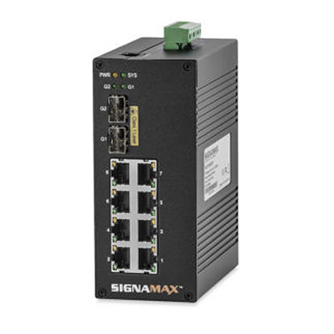
  9. SignaMax I-120 Series User manual

SignaMax I-120 Series User manual

Quick Start Guide
www.signamax.com
QSG-SI120XX_A-7-21
www.signamax.com
999 N.W. 159th Drive
Miami, FL 33169
Tel: 800.446.2377
COPYRIGHT 2007 SIGNAMAX, INC. ■ ALL RIGHTS RESERVED ■ SPECIFICATIONS SUBJECT TO CHANGE
CONNECT WITH US
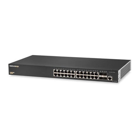
I-120 Series Industrial Switches
Part Num-
ber
Primary
Ports Uplink PoE
Budget
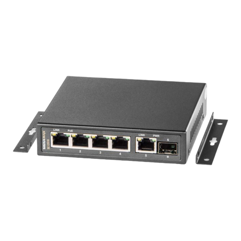
SI12010 4 Gigabit 1 SFP
1 Gigabit 240W
Unpack the Switch and Check Contents
DIN-Rail Mounting Kit - one bracket and two
screws.
Documentation—Quick Start Guide (this docu-
ment) and Warranty Card
Note: Additional documentation can be obtained from
www.signamax.com
Warning: This product does not contain any serviceable user
parts.
Warning: Installation and removal of the unit must be carried out
by qualied personnel only.
Warning: When connecting this device to a power outlet, connect
the eld ground lead on the tri-pole power plug to a valid earth
ground line to prevent electrical hazards.
Warning: This switch uses lasers to transmit signals over ber
optic cable. The lasers are compliant with the requirements of
a Class 1 Laser Product and are inherently eye safe in normal
operation. However, you should never look directly at a transmit
port when it is powered on.
Warning: When selecting a ber SFP device, considering safety,
please make sure that it can function at a temperature that is not
less than the recommended maximum operational temperature of
the product. You must also use an approved Laser Class 1 SFP
transceiver.
Caution: Wear an anti-static wrist strap or take other suitable
measures to prevent electrostatic discharge when handling this
equipment.
Caution: Do not plug a phone jack connector in the RJ-45 port.
This may damage this device.
Caution: Use only twisted-pair cables with RJ-45 connectors that
conform to FCC standards.
!
!
Mount the Switch
1. Screw the DIN-Rail bracket to the switch.
2. Insert the top of the DIN-Rail bracket to the DIN-Rail track.
3. Pull down the DIN-Rail bracket to the DIN-Rail track and check if it is
mounted tightly on the DIN-Rail track.
Warnings and Cautionary Messages
1. This equipment must be grounded. Never defeat the ground conductor
or operate the equipment in the absence of a suitably installed ground
conductor. Contact the appropriate electrical inspection authority or an
electrician if you are uncertain that suitable grounding is available.
2. Attach a lug (not provided) to a #12 AWG (PoE switch) or #18 AWG
(non-PoE switch) minimum grounding wire (not provided), and connect
it to the grounding point on the switch rear panel. Then connect the other
end of the wire to ground.
Ground the Switch
Caution: The earth connection must not be removed unless all
supply connections have been disconnected.
Note: The device must be installed in a restricted access loca-
tion. It should have a separate protective earthing terminal on
the chassis that must be permanently connected to earth to ad-
equately ground the chassis and protect the operator from elec-
trical hazards.
!
1. The I-120 Series PoE Ports all support 802.3bt up to 95W per port.
2. Total available PoE budget for the whole switch is presented in the
table above.
www.signamax.com
999 N.W. 159th Drive
Miami, FL 33169
Tel: 800.446.2377 CONNECT WITH US
QSG-SI120XX_A-7-21
COPYRIGHT 2007 SIGNAMAX, INC. ■ ALL RIGHTS RESERVED ■ SPECIFICATIONS SUBJECT TO CHANGE
Quick Start Guide
I-120 Series Industrial Switches
1. Insert the positive and negative wires into the PWR1 (+,-) and/or PWR2
(+,-) on the terminal block connector (only one power supply is required).
2. Tighten the screws to prevent the wires from loosening.
3. Only one power supply is required for operation of the switch. Dual
power sources are for redundancy
PWR 2 PWR 1
1. For RJ-45 ports, connect 100-ohm Category 5, 5e or better twisted-pair
cable
2. For the SFP slots, rst install SFP transceivers and then connect ber
optic cabling to the transceiver ports. The following transceivers are sup-
ported:
1000BASE-SX (065-79SXMG-H)
1000BASE-LX (065-79LXMG-H)
1000BASE-ZX (065-79ZXMG-H)
1000BASE-LHX (065-79LXEDMG-H)
100FX Multimode (AS11010)
100LX Singlemode (AS11020)
3. As connections are made, check the port status LEDs to be sure the
links are valid. See the LED description table on the next page.
1. Verify basic switch operation by checking the system LEDs. When oper-
ating normally, the Power LED should be on and green.
Connect Power
Verify Switch Operations
Connect Network Cables
LED Status Description
PWR ON Switch operating normally.
OFF No DC power is connected or the switch has failed.
LINK
ON Port has a valid link
BLINKING Port has network activity
OFF The link is down
PoE
ON A PoE device is connected and delivered PoE power
BLINKING PoE Error: short circuit or current overload
OFF Doesn’t deliver PoE power
LED Description Table

This manual suits for next models

1

Other SignaMax Switch manuals

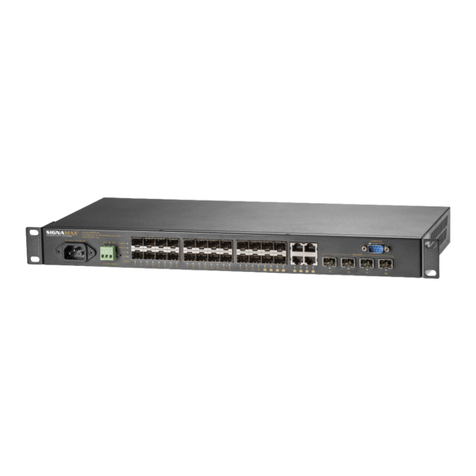
SignaMax 065-7905A User manual

SignaMax

SignaMax 065-7905A User manual

SignaMax 065-7931 User manual

SignaMax

SignaMax 065-7931 User manual

SignaMax 098-8280 User manual

SignaMax

SignaMax 098-8280 User manual

SignaMax FO-065-7030Q User manual

SignaMax

SignaMax FO-065-7030Q User manual

SignaMax C-500 Series User manual

SignaMax

SignaMax C-500 Series User manual

SignaMax 065-7910HPOEP User manual

SignaMax

SignaMax 065-7910HPOEP User manual

SignaMax 065-7013PD User manual

SignaMax

SignaMax 065-7013PD User manual

SignaMax FO-065-7110 Series User manual

SignaMax

SignaMax FO-065-7110 Series User manual

SignaMax 065-7310F Series User manual

SignaMax

SignaMax 065-7310F Series User manual

SignaMax 065-7401 User manual

SignaMax

SignaMax 065-7401 User manual

SignaMax 065-7940D-WS User manual

SignaMax

SignaMax 065-7940D-WS User manual

SignaMax C-310 Series User manual

SignaMax

SignaMax C-310 Series User manual

SignaMax C-600 Series User manual

SignaMax

SignaMax C-600 Series User manual

SignaMax C-120 Series User manual

SignaMax

SignaMax C-120 Series User manual

SignaMax 065-7407GPOEP User manual

SignaMax

SignaMax 065-7407GPOEP User manual

SignaMax SC10010 User manual

SignaMax

SignaMax SC10010 User manual

SignaMax 065-7726SPOE User manual

SignaMax

SignaMax 065-7726SPOE User manual

SignaMax FO-065-7330 User manual

SignaMax

SignaMax FO-065-7330 User manual

SignaMax C-500 Series User manual

SignaMax

SignaMax C-500 Series User manual

SignaMax 065-7921PoE User manual

SignaMax

SignaMax 065-7921PoE User manual

SignaMax 065-7434 User manual

SignaMax

SignaMax 065-7434 User manual

SignaMax 065-7528 User manual

SignaMax

SignaMax 065-7528 User manual

SignaMax 500-7622GE2GS User manual

SignaMax

SignaMax 500-7622GE2GS User manual

SignaMax 065-7508 User manual

SignaMax

SignaMax 065-7508 User manual

Popular Switch manuals by other brands

Belkin F1DN104K-3 user manual

Belkin

Belkin F1DN104K-3 user manual

Dataprobe 4P-MAS quick start guide

Dataprobe

Dataprobe 4P-MAS quick start guide

Avaya M770 user guide

Avaya

Avaya M770 user guide

Hawking H-FS24T specification

Hawking

Hawking H-FS24T specification

Edirol V-Link LVS-800 owner's manual

Edirol

Edirol V-Link LVS-800 owner's manual

Vimar 6592 Installer's guide

Vimar

Vimar 6592 Installer's guide

UTEPO UTP3-SW08-TP120 user manual

UTEPO

UTEPO UTP3-SW08-TP120 user manual

Leonton PG2-0601-SFP Series user manual

Leonton

Leonton PG2-0601-SFP Series user manual

Smart-M DVN-2P quick start guide

Smart-M

Smart-M DVN-2P quick start guide

Quintum Tenor BX Product guide

Quintum

Quintum Tenor BX Product guide

Lantronix LFH8-S installation guide

Lantronix

Lantronix LFH8-S installation guide

Siemens SITRANS LPS200 operating instructions

Siemens

Siemens SITRANS LPS200 operating instructions

ALLEN & HEATH DX-HUB manual

ALLEN & HEATH

ALLEN & HEATH DX-HUB manual

ATCOM APBX IP01 user manual

ATCOM

ATCOM APBX IP01 user manual

Belden HIRSCHMANN OCTOPUS OS3 user manual

Belden

Belden HIRSCHMANN OCTOPUS OS3 user manual

ANTAIRA LNX-602N user manual

ANTAIRA

ANTAIRA LNX-602N user manual

HP J3175A Installation and reference guide

HP

HP J3175A Installation and reference guide

Lantronix SISGM1040-284-LRT install guide

Lantronix

Lantronix SISGM1040-284-LRT install guide

manuals.online logo
manuals.online logoBrands
  • About & Mission
  • Contact us
  • Privacy Policy
  • Terms and Conditions

Copyright 2025 Manuals.Online. All Rights Reserved.