manuals.online logo
Brands
  1. Home
  2. •
  3. Brands
  4. •
  5. SIGNIFY
  6. •
  7. Lantern
  8. •
  9. SIGNIFY Ledalite MicroSwuare gen 2 User manual

SIGNIFY Ledalite MicroSwuare gen 2 User manual

Other SIGNIFY Lantern manuals

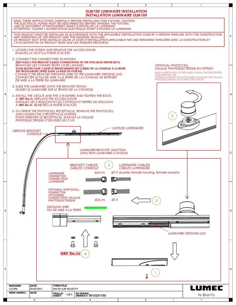
SIGNIFY LUMEC ULM100 User manual

SIGNIFY

SIGNIFY LUMEC ULM100 User manual

SIGNIFY LUMEC TULS User manual

SIGNIFY

SIGNIFY LUMEC TULS User manual

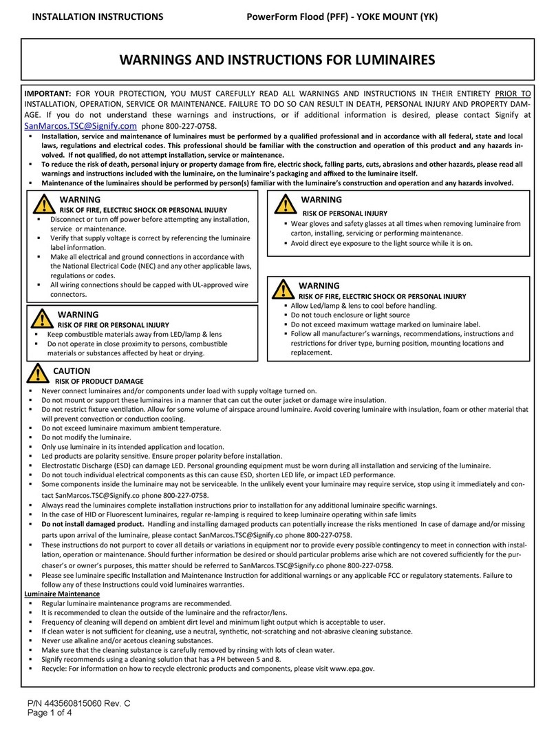
SIGNIFY Gardco PowerForm PFF Series User manual

SIGNIFY

SIGNIFY Gardco PowerForm PFF Series User manual

SIGNIFY GARDCO PowerForm User manual

SIGNIFY

SIGNIFY GARDCO PowerForm User manual

SIGNIFY Lumec Serenade DSX User manual

SIGNIFY

SIGNIFY Lumec Serenade DSX User manual

Popular Lantern manuals by other brands

DS Produkte TRF18P0752-1 instructions

DS Produkte

DS Produkte TRF18P0752-1 instructions

Stahl ECOLUX 6610 Series operating instructions

Stahl

Stahl ECOLUX 6610 Series operating instructions

SNOWJOE SUNJOE 24V-LGT500-CT Operator's manual

SNOWJOE

SNOWJOE SUNJOE 24V-LGT500-CT Operator's manual

PRG VARI LITE VL5 Service manual

PRG

PRG VARI LITE VL5 Service manual

Raytec VARIO2 series installation guide

Raytec

Raytec VARIO2 series installation guide

ENSA LEDBT18WS2 installation instructions

ENSA

ENSA LEDBT18WS2 installation instructions

LUG OFFICE LB LED N/T Installation instruction

LUG

LUG OFFICE LB LED N/T Installation instruction

Draper RLEDL19/B instructions

Draper

Draper RLEDL19/B instructions

Green Lighting TRI-SENSOR GL4612LU Assembly & fitting instructions

Green Lighting

Green Lighting TRI-SENSOR GL4612LU Assembly & fitting instructions

Panasonic EY3741B57 operating instructions

Panasonic

Panasonic EY3741B57 operating instructions

Clas Ohlson LCC8T instruction manual

Clas Ohlson

Clas Ohlson LCC8T instruction manual

Coolon WDN-140 manual

Coolon

Coolon WDN-140 manual

shada 1000436 instruction manual

shada

shada 1000436 instruction manual

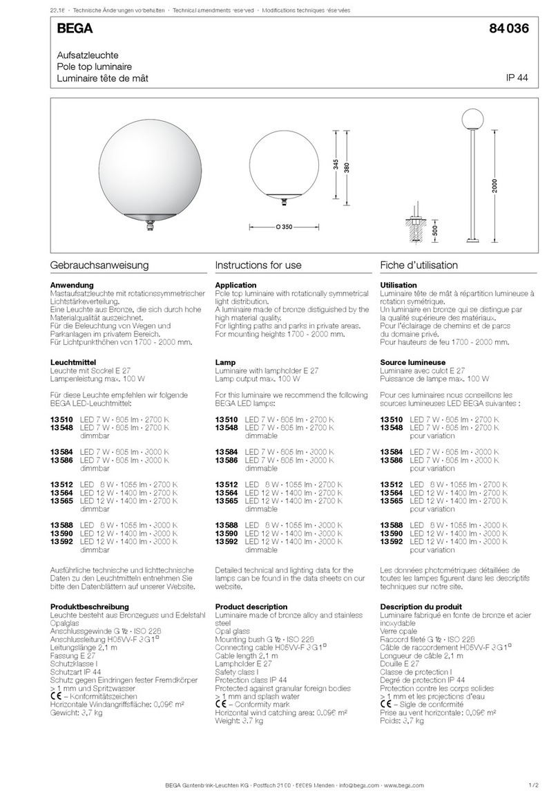
BEGA 84 036 Instructions for use

BEGA

BEGA 84 036 Instructions for use

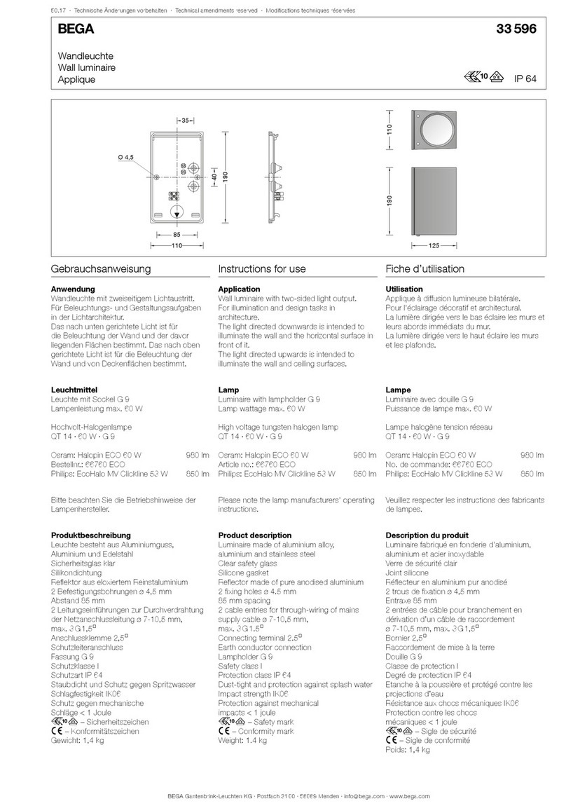
BEGA 33 596 Instructions for use

BEGA

BEGA 33 596 Instructions for use

Dale Tiffany GT701162 Assembly instructions

Dale Tiffany

Dale Tiffany GT701162 Assembly instructions

Wagan Brite Nite Pop-Up USB Lantern user manual

Wagan

Wagan Brite Nite Pop-Up USB Lantern user manual

Eaton Crouse-Hinds Pauluhn DLLA M2 Series Installation & maintenance information

Eaton

Eaton Crouse-Hinds Pauluhn DLLA M2 Series Installation & maintenance information

manuals.online logo
manuals.online logoBrands
  • About & Mission
  • Contact us
  • Privacy Policy
  • Terms and Conditions

Copyright 2025 Manuals.Online. All Rights Reserved.

ATTENTION: Install in accordance with national and local building and electrical codes.
! Page 1
Mount Spacing
MicroSquare gen 2 fixture modules are designed for exact on-grid
mounting with mounts attached to the joiner assemblies.
MicroSquare gen 2 Endcap Kit(s)
• Endcap
• Joiner bracket
• 2x joiner aligners
System Overview
These instructions review how to install MicroSquare gen 2 suspended fixtures. MicroSquare 4ft, 6ft and 8ft
modules can be installed as individual standalone units, or they can be joined together to create continuous
runs. The graphics below show the components required to install a typical run of MicroSquare gen 2 sus-
pended fixtures. IMPORTANT: Read all instructions before beginning installation.
Module Lengths
MicroSquare suspended fixtures come in 4ft, 6ft and 8ft modules.
Overall module lengths are shown below. Add 2.2” for each
endcap for accurate run length.
48”
72”
96”
4FT Module
6FT Module
8FT Module
Tools
Required:
• Philips screwdriver
MicroSquare gen 2 Joint Kit(s)
• Joiner bracket
• 2x joiner aligner
ATTENTION: Install in accordance with national and local building and electrical codes.
! Page 2
2
Arrange boxed fixture on floor in specified mounting location, remove fixtures from boxes. Install all ceiling mounting components and vertical aircraft cables using separate installation instruction for Aircraft
Cable Mounting (supplied).
1
Hang joiner brackets at mounting locations. Bottom lens will be
1.9” (48mm) lower than the bottom of the mounting bracket. Assure that
the brackets are at the desired height and trim aircraft cable to length.
Insert joiner bracket squarely into sheet metal
crossplate
Remove lens from fixture and set aside
until fixture installation is complete. Use
cotton gloves to handle lenses and keep in
a clean environment.
Symmetric Cross Secon
Lens Removal
“CLICK”
3Install Suspension Cables and Joiners 4Clip in Non Power Side of Luminaire
5Clip Detail 6Listen and Feel Click 7Power Cord Install/routing 8Hook Up Power Cord
Clip in far side from power drop.
Top tabs of the joiner bracket should go
between the extrusion and sheet metal cross
plate. Joiner bracket should seat fully and an
audible and tactile click should be heard.
Feed power cable through knockout in the
top of the luminaire and out the end of
fixture. Add strain relief to power cord.
Connect power cable to through wiring
already present in the luminaire. Once
connected push wires at least 2” (50mm)
into luminaire.
ATTENTION: Install in accordance with national and local building and electrical codes.
! Page 3
910 12
Slide joiner bracket into power entry side of the luminaire.
Clip in Power Side of Luminaire Listen and Feel Click Insert Aligning Tabs
“CLICK”
“CLICK”
13 Click In Far End and Insert Aligning Tabs 12 Connect Power Wires 13 Listen For Click
Top tabs of the joiner bracket should go
between the extrusion and sheet metal cross
plate. Joiner bracket should seat fully and an
audible and tactile click should be heard.
Slide joiner aligners into bottom extrusion
detail. Ensure the small bump on the aligner
is toward the lens. *Note location of small
bump should always be on the bottom
Slide joiner bracket into far side of the next luminaire in the row. Ensure that the bracket is fully seated and clicks
into place. Slide luminaire onto aligner brackets of the previous luminaire.
Connect wiring of adjacent luminaires. Once
connected push wiring connectors at least
2” (50mm) into luminaire.
Push luminaires and together
listen for a click as the joiner
bracket is located.
ATTENTION: Install in accordance with national and local building and electrical codes.
! Page 4
15 16
Endcap Preparation Install Endcap
“CLICK”
14 Tighten Screws Listen For Click
17
18 Tighten Screws 19 Reinstall Lens and Endcap Plate
Tighten the screws alternating between the
two.
Remove the bottom cover from the endcap. Install the joiner aligners making sure to keep the small tab toward the bottom.
Slide the endcap over the joiners and onto the joiner bracket.
Listen for a click as the joiner
bracket is located.
Tighten the screws alternating between the
two.
Reinstall the lens and Endcap plate.