SigTEL Compact Manual

SigTEL Compact
Emergency Voice
Communication
System (EVCS)
Installation and
Configuration
Manual
Approved Document No. DAU0000091 Rev 5

SigTEL Compact Installation and Configuration Manual
SigTEL Approved Document No. DAU0000091 Rev 5 Page 2 of 36
Emergency Voice
Communication System
AN EXPLANTION OF TERMS AND DEFINITIONS USED IN THESE INSTRUCTIONS IS LISTED IN SECTION 21.
Contents
1IMPORTANT NOTES......................................................................................................................................................4
2REGULATIONS AFFECTING EVCS ...................................................................................................................................4
3SIGTEL COMPACT COMPONENTS .................................................................................................................................5
3.1 MCU (PART NOS.ECU-4, ECU-8, ECU-16) ......................................................................................................................5
3.2 LCU (PART NO.ECU-8NT)..............................................................................................................................................5
3.3 GREY FLUSH BEZEL (PART NO.AFP385) .............................................................................................................................5
3.4 TYPE AFIRE TELEPHONE OUTSTATION (PART NOS.EVC301RPO, EVC301RLK).......................................................................5
3.5 FLUSH-MOUNTING BEZEL (PART NO.T-BEZ301)..................................................................................................................5
3.6 TYPE BDISABLED REFUGE OUTSTATION -SURFACE MOUNTED (PART NO.EVC302S/GS) ............................................................5
3.7 TYPE BDISABLED REFUGE OUTSTATION -FLUSH MOUNTED (PART NO.EVC302F/GF)................................................................6
3.8 TYPE BOUTSTATION ENCLOSURE (PART NO.BF359/1) .........................................................................................................6
3.9 MCU ENCLOSURE (PART NO.BF359/3D) ..........................................................................................................................6
3.10 DISABLED PERSONS TOILET ALARM (PART NO.NC951) ..........................................................................................................6
3.11 NETWORK COMMUNICATIONS CARD (PART NO.ECU722)......................................................................................................6
3.11.1 Key features of the EVCS networked system: ..............................................................................................7
4CABLES .........................................................................................................................................................................7
5TYPICAL SYSTEMS.........................................................................................................................................................8
5.1 SYSTEM UP TO 4EXTENSIONS............................................................................................................................................8
5.2 SYSTEM UP TO 8EXTENSIONS............................................................................................................................................8
5.3 SYSTEM UP TO 16 EXTENSIONS..........................................................................................................................................9
5.4 NETWORKED SYSTEM UP TO 224 EXTENSIONS....................................................................................................................10
6FIRST FIX INSTALLATION.............................................................................................................................................11
6.1 EQUIPMENT LOCATION ..................................................................................................................................................11
7MOUNTING ENCLOSURES........................................................................................................................................... 12
7.1 REMOVE THE BASE PCBS...............................................................................................................................................12
7.2 REMOVE THE LID ..........................................................................................................................................................12
7.3 REMOVE KNOCKOUTS &CUT GLAND HOLES .......................................................................................................................12
7.4 FIX THE BASE TO THE WALL .............................................................................................................................................13
7.5 RE-INSTALL THE BASE PCBS............................................................................................................................................14
8INSTALLING THE ECU722 NETWORK COMMS CARD (OPTIONAL)................................................................................ 15
9NETWORK CONNECTIONS (OPTIONAL).......................................................................................................................16
10 MAINS WIRING ..........................................................................................................................................................17
11 FITTING OUTSTATIONS & DPTA INTERFACE................................................................................................................18
11.1 CABLES.......................................................................................................................................................................18
11.2 LOCATION ...................................................................................................................................................................18
11.3 FITTING TYPE AOUTSTATION (EVC301RPO/EVC301RLK) ................................................................................................18
11.4 FITTING TYPE BOUTSTATION (EVC302S/GS AND EVC302F/GF) ........................................................................................18
11.5 WIRING TO A DISABLED PERSONS TOILET ALARM (DPTA) .....................................................................................................18
12 TESTING EXTENSIONS.................................................................................................................................................19
12.1 INSULATION RESISTANCE TESTING.....................................................................................................................................19
12.2 THE FITT LINE TESTER....................................................................................................................................................19

SigTEL Compact Installation and Configuration Manual
SigTEL Approved Document No. DAU0000091 Rev 5 Page 3 of 36
Emergency Voice
Communication System
13 SECOND FIX INSTALLATION ........................................................................................................................................ 19
13.1 CONNECTING EXTENSIONS TO THE MCU/LCU ...................................................................................................................19
13.2 FAULT MONITORING......................................................................................................................................................19
13.3 INPUT CONNECTIONS.....................................................................................................................................................20
13.4 OUTPUT CONNECTIONS..................................................................................................................................................20
14 MCU/LCU INDICATORS & CONTROLS .........................................................................................................................21
14.1 EXTERNAL INDICATORS ..................................................................................................................................................21
14.2 THE DISPLAY ................................................................................................................................................................21
14.3 EXTERNAL CONTROLS ....................................................................................................................................................22
14.4 INTERNAL CONTROLS .....................................................................................................................................................22
15 FAULT MESSAGES ....................................................................................................................................................... 22
16 POWERING UP AND TESTING .....................................................................................................................................23
17 AUTOMATIC CONFIGURATION ...................................................................................................................................24
17.1 SINGLE,NON-NETWORKED MCU CONFIGURATION .............................................................................................................24
17.2 NETWORKED MCU/LCU CONFIGURATION........................................................................................................................25
17.3 ADDING OR REPLACING MCU/LCU, OUTSTATIONS OR DPTA AFTER COMMISSIONING...............................................................27
17.4 DEFAULT EXTENSION NAMES...........................................................................................................................................27
17.5 NAMING EXTENSIONS....................................................................................................................................................27
17.5.1 Interactive naming ....................................................................................................................................28
17.5.2 Manual naming .........................................................................................................................................28
17.5.3 EVC Configurator .......................................................................................................................................28
18 ADDITIONAL ENGINEER FUNCTIONS........................................................................................................................... 29
18.1 CHANGE THE SECURITY PIN CODE ....................................................................................................................................29
18.2 HARMONISE NAMES (NETWORKED SYSTEM ONLY)...............................................................................................................29
18.3 LATCH FAULTS..............................................................................................................................................................30
18.4 CLEAR RECENT CALLS .....................................................................................................................................................31
18.5 AUTO-ANSWER ............................................................................................................................................................31
19 COMPONENT SPECIFICATIONS ...................................................................................................................................32
19.1 FIRMWARE VERSION......................................................................................................................................................34
20 INSTALLATION AND COMMISSIONING CERTIFICATE...................................................................................................35
21 TERMS AND DEFINITIONS........................................................................................................................................... 36
Errors and omissions excepted. The manufacturer of this product operates a policy of continuous improvement and reserves the right to
alter product specifications at its discretion and without prior notice. All of the instructions covered in this manual have been carefully
checked prior to publication. However, no responsibility can be accepted by the manufacturer for any inaccuracies, or any misinterpretations
of an instruction or guidance note.

SigTEL Compact Installation and Configuration Manual
SigTEL Approved Document No. DAU0000091 Rev 5 Page 4 of 36
Emergency Voice
Communication System
1 Important Notes
READ THIS SECTION BEFORE INSTALLING/MAINTAINING THIS PRODUCT
CAUTION
This equipment must only be installed and maintained by a suitably skilled and technically competent
person. No responsibility can be accepted by the manufacturer, or distributors of this product for any
misinterpretation of an instruction, or guidance note, or for the compliance of the system as a whole.
About this guide
This guide explains how to install, commission and maintain a SigTEL EVCS disabled refuge and fire telephone
system. A separate user manual (ref. DAU0000092) includes detailed operational information, some of which will
need to be referred to by the installation engineer when setting up the system.
No responsibility can be accepted by the manufacturer, or distributors for any misinterpretation of these instructions,
or for the compliance of the system as a whole.
This installation guide must not be accessible to the user.
System design
EVCS design is beyond the scope of this document. An understanding of system components and their use is
assumed.
We recommend that you read the latest edition of BS 5839 Part 9 (available from the BSI, http://www.bsigroup.com,
for this information. Contact the building control, or fire officer in case he has any special requirements.
Equipment guarantee
This equipment is not guaranteed unless the system is installed and commissioned in accordance with national
standards by an approved and competent person, or organisation.
General precautions
Do not test wiring with an insulation tester (Megger) with any equipment connected as the 500 volt test will destroy
these devices totally. You must observe local wiring regulations.
Do not run SELV and LV cables in the same enclosure without adequate insulation between them.
SigTEL EVCS control equipment is designed to be installed indoors. Outstations are not IP rated so should not be
installed outdoors unless an IP65, or better housing, is used and cables are installed so as to prevent the ingress of
moisture.
Anti-static handling guidelines
Make sure that electro-static handling precautions are taken immediately before handling PCBs and
other static sensitive components. Before handling any static-sensitive items, Operators should get
rid of any electrostatic charge by touching a sound safety earth.
Always handle PCBs by their sides and avoid touching any components. PCBs should be stored in
a clean, dry place that is free from vibration, dust and excessive heat. Storing the PCBs in a suitable
cardboard box will also guard them against mechanical damage.
2 Regulations Affecting EVCS
Disabled refuge systems are called for by DETR Approved document B (Fire safety) volume 2, section 4, Design for
vertical escape and BS 5588 Fire precautions in the design, construction and use of buildings, Part 8, Code of
practice for means of escape for disabled people.
Fire telephone systems for buildings are called for by BS 5588 Fire precautions in the design, construction and use
of buildings Part 5, Code of practice for firefighting stairs and lifts, Part 10, Code of practice for shopping complexes
and Part 11, Code of practice for shops, offices, industrial, storage and other similar buildings.
Fire telephone systems for sports venues are called for by the Guide to safety at sports grounds.
The installation of EVCS’s is covered by BS 5839-9 Fire detection and fire alarm systems for buildings – Part 9:
Code of practice for the design, installation, commissioning and maintenance of emergency voice communication
systems.

SigTEL Compact Installation and Configuration Manual
SigTEL Approved Document No. DAU0000091 Rev 5 Page 5 of 36
Emergency Voice
Communication System
3 SigTEL Compact Components
Note: See Specification (section 19) for component details.
3.1
MCU (part nos. ECU-4, ECU-8, ECU-16)
The master control unit (MCU) controls the EVCS and allows the MCU’s Operator
to communicate with the outstations.
Each MCU has either four extensions (ECU-4), eight extensions (ECU-8), or 16
extensions (ECU-16).
One extension typically has one outstation (Type A or B) or a DPTA connected.
A flush bezel (AFP385) and an anti-tamper enclosure (BF359/3D) are available
to house the unit.
Note: Up to 14 MCUs and LCUs can be connected on a network by installing a
Network Communications Card (ECU722) in each unit.
3.2
LCU (part no. ECU-8NT)
The line control unit (LCU) is identical to an MCU but it does not have a handset
mounted on its front. Each LCU has eight extensions.
3.3
Grey flush bezel (part no. AFP385)
This flush mounting bezel is used with the MCU/LCU and provides a neat finish when an enclosure is semi-recessed
(up to 60 mm).
3.4
Type A Fire Telephone Outstation (part nos. EVC301RPO, EVC301RLK)
One Type A outstation is connected to one extension so that the control room can call out to
specific locations and also know which location is calling in.
The outstation consists of a telephone-style handset housed within a wall-mounted, red steel
case. Two versions are available a magnetic ‘push to open’ version (EVC301RPO) right, and
a ‘lift lock’ version (EVC301RLK) used to prevent unauthorised access.
Both units can be surface mounted, or a flush mounting bezel (T-BEZ301) is available.
3.5
Flush -mounting bezel (part no. T-BEZ301)
This red flush bezel provides a neat finish when a Type A fire telephone is semi-recessed.
3.6
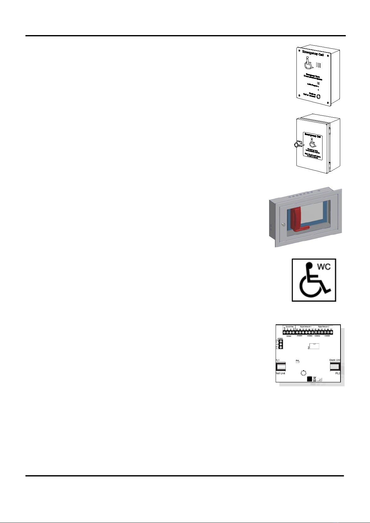
Type B Disabled Refuge Outstation - surface mounted (part no. EVC302S/GS)
One Type B outstation is connected to one extension so that the control room can call out to
specific locations and also know which location is calling in. The EVC302S has a stainless
steel fascia and the EVC302GS has a green mild steel fascia. Both units use hands-free,
duplex operation and have a ‘Push to Call or Answer’ button, Call in Progress LED, buzzer
and apertures for a microphone and loudspeaker.
SigTEL Compact Installation and Configuration Manual
SigTEL Approved Document No. DAU0000091 Rev 5 Page 6 of 36
Emergency Voice
Communication System
3.7
Type B Disabled Refuge Outstation - flush mount ed (part no. EVC302F/GF)
Identical to the EVC302S/GS version but with a flat fascia suitable for flush installation. The
EVC302F has a stainless steel fascia and the EVC302GF has a green mild steel fascia. An
IP66 rated housing (BF359/1) is available to allow the outstation to be used outdoors.
3.8
Type B outstation enclosure (part no. BF359/1)
This weatherproof enclosure is used to protect an EVC302F/GF outstation when used at an
external disabled refuge. It is supplied with a non-locking handle (as disabled refuge points
should not normally be locked) and has an IP66 rating.
3.9
MCU enclosure (part no. BF359/3D)
This is a stainless steel, anti-tamper enclosure used to house an MCU. It is supplied
with two optional locking kits; BF359/3CL (camlock kit) or BF359/3SL (solenoid kit).
3.10
Disabled persons toilet alarm (part no. NC951)
The EVCS is able to interface to a disabled persons toilet alarm (DPTA) system. This is a
secondary function to the primary purpose of the EVCS. If the site has toilet alarms AND
they are connected into the EVCS, then active toilet alarms will be displayed at the
MCU/LCU. As toilet alarm monitoring is a secondary function, any activated toilet alarms will
be suppressed from being displayed if there are any calls from/to any outstations. At the end
of outstation calls the activated toilet alarms will then be displayed.
3.11
Network communication s card (part no. ECU722)
The ECU722 Network Communications Card enables up to 14 MCUs or LCUs to be
connected on a communication network, up to 1 km in length. Any MCU/LCU connected
on the network requires the installation of an ECU722 card which is mounted inside the
control unit and transmits both speech audio and digital data.

SigTEL Compact Installation and Configuration Manual
SigTEL Approved Document No. DAU0000091 Rev 5 Page 7 of 36
Emergency Voice
Communication System
3.11.1 Key features of the EVCS networked system:
1. Allows the interconnection of up to 14 MCUs or LCUs using 4 x 2-core, 1.5 mm2, enhanced fire-rated wiring.
2. Maximum length on the speech wiring loop, or digital linear wiring = 1 km.
3. Each MCU/LCU monitors both the network wiring and each other for faults (open and short circuits).
4. Fault tolerant network that allows the system to continue working in the event of a single cable break in the
speech or digital wiring. Speech audio is transmitted via one wiring loop and digital data via two linear RS485
networks.
5. Each networked MCU can be programmed with the following configuration:
•One MCU is configured as the ‘master’ MCU and has control over the system. The other MCUs act as repeaters but
can take control from the master MCU when a security PIN code is entered, either at the master MCU, or a repeater
MCU. For example, control can be transferred from one control point in a building to another to cater for different
day/night shift patterns.
•The master MCU displays the location of calls and the description of faults on the EVCS. Faults on repeater MCUs
are displayed at the master MCU as remote faults.
•Calls from any outstation, regardless of which MCU they are connected to, are automatically routed to the master
MCU. Repeater MCUs indicate that units are calling the master MCU and can take control of the system by picking
up their handsets and entering a security PIN code.
•Ability to take control from the master MCU at any repeater MCU (by entering a security PIN code). For example,
the nearest MCU to the building entry point. Also, able to give control from the master MCU to any repeater MCU
(by entering a security PIN code).
•Changes made at the master MCU (e.g. security PIN codes, extension names, addition/removal of an outstation or
MCU) are automatically updated on all repeater MCUs.
•The master MCU is automatically dialled to by repeater MCUs when their handsets are picked up (in ‘no-call’ mode).
4 Cables
Generally, cables used between EVCS components, and for the low voltage Mains supply to the system, should be enhanced
fire-resistant [see 26.2e of BS 5839-1]. Please note the following exceptions.
BS 5839-9: section 14 the following recommendations are applicable:
c) Standard fire resisting cables [see 26.2d of BS 5839-1] should be considered to provide sufficient resistance to the effects of
fire with appropriate methods of support and jointing [see 26.2g of BS 5839-1] for:
1) EVC systems for use in disabled refuges but not for fire-fighting or similar purposes by, e.g. the fire and rescue service, in:
•i) sprinklered buildings;
•ii) unsprinklered buildings less than 30 m in height, provided that evacuation takes place in three or fewer phases.
2) Underground sections of cabling at sports and similar venues.
Interconnection Cable Type
Extensions to outstations
2-core, 1.0 mm2or 1.5 mm2cable is recommended for each extension. Larger
cables will stress the connectors. The maximum cable resistance is 40 ohms, which
is 1 km of 1.0 mm2. If this is exceeded audio quality will degrade.
Extensions to DPTA systems (NC951) 2-core cable is required for each extension.
Power supplies
The MCU/LCU requires fixed wiring using 2-core cable and earth/CPC cable (no
less than 0.75 mm2and no more than 2.5 mm2) fed from an isolating switched fused
spur, fused at 3 amps. A plug and socket MUST NOT be used.
Networked systems
Either MCU to MCU
Or,
MCU to LCU
4 x 2-core, 1.5 mm2, up to 1 km in length. This cable connects ECU722 cards
mounted inside the MCU/LCU.
Note: To provide full network reliability only 2-core cable should only be used. This
allows two separate cable paths to be run with each path containing a single speech
and data cable (which should not be mixed in the same cable).
MCU/LCU to ECU722 – Networked
systems
Connects the MCU/LCU to the ECU722 comms card using one Cat 5 patch cable
(supplied with ECU722).

SigTEL Compact Installation and Configuration Manual
SigTEL Approved Document No. DAU0000091 Rev 5 Page 8 of 36
Emergency Voice
Communication System
5 Typical Systems
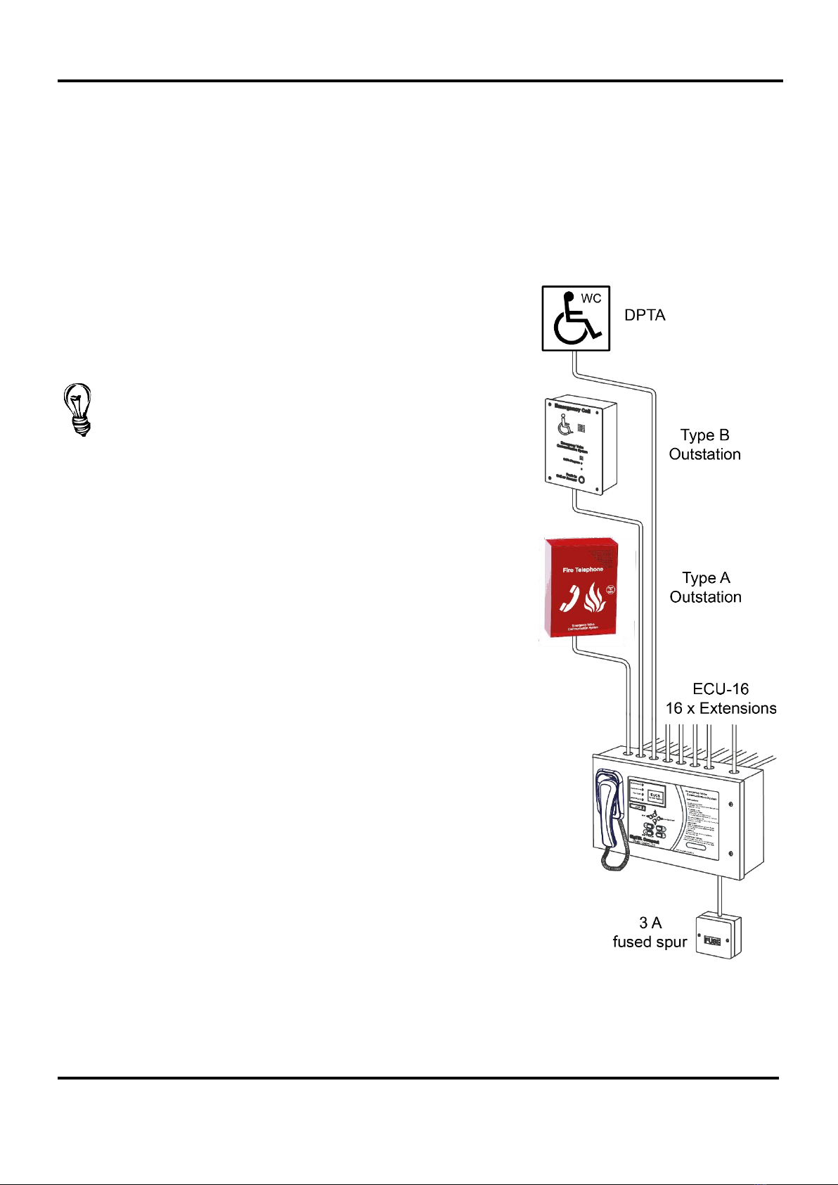
5.1
System up to 4 extension s
Equipment required (shown right)
One MCU (ECU-4), requires two 12 volt 7 Ah batteries (BC286/2).
One 3 A fused spur and back box.
One Type A Outstation (EVC301RPO/EVC301RLK), or one Type B Outstation
(EVC302F/GF/S/GS), or one DPTA (NC951) per extension.
One Telephone Line Tester (FiTT).
Interconnections
For each extension to outstation: up to 1 km of 2-core, 1.5 mm2enhanced
fire-rated cable.
For each extension to DPTA (NC951): 2-core cable.
5.2
System up to 8 extension s
Equipment required (shown left)
One MCU (ECU-8), requires two 12 volt 7 Ah batteries (BC286/2).
One 3 A fused spur and back box.
One Type A Outstation (EVC301RPO/EVC301RLK ), or one Type
B Outstation (EVC302F/GF/S/GS), or one DPTA (NC951) per
extension.
One Telephone Line Tester (FiTT).
Interconnections
For each extension to outstation: up to 1 km of 2-core, 1.5 mm2
enhanced fire-rated cable.
For each extension to DPTA (NC951): 2-core cable.
SigTEL Compact Installation and Configuration Manual
SigTEL Approved Document No. DAU0000091 Rev 5 Page 9 of 36
Emergency Voice
Communication System
5.3
System up to 16 extension s
Equipment required
One MCU (ECU-16), requires two 12 volt 7 Ah batteries (BC286/2).
One 3 A fused spur and back box.
One Type A Outstation (EVC301RPO/RLK), or one Type B Outstation (EVC302F/GF/S/GS), or one DPTA (NC951)
per extension.
One Telephone Line Tester (FiTT).
Interconnections
For each extension to outstation: up to 1 km of 2-core, 1.5 mm2enhanced
fire-rated cable.
For each extension to DPTA (NC951): 2-core cable.
Application Note 0012.0 details a suggested method when wiring
FP200 cable to an ECU-16 panel using a junction box.
See www.c-tec.com.

SigTEL Compact Installation and Configuration Manual
SigTEL Approved Document No. DAU0000091 Rev 5 Page 10 of 36
Emergency Voice
Communication System
5.4
Networked s ystem up to 224 extensions
Equipment required
Up to 14 MCU (ECU-16), requires two 12 volt 7 Ah batteries (BC286/2) per MCU.
One 3 A fused spur and back box per MCU.
One Type A Outstation (EVC301RPO/RLK), or one Type B Outstation (EVC302F/GF/S/GS), or one DPTA (NC951)
per extension.
One Telephone Line Tester (FiTT).
Interconnections
For each extension to outstation: up to 1 km of 2-core, 1.5 mm2enhanced fire-rated cable.
For each extension to DPTA (NC951): 2-core cable.
Network Connections (MCU to MCU): 4 x 2-core, 1.5 mm2, enhanced fire-rated cable. This allows two separate cable
paths (Cable Paths 1 & 2) to be run with each path containing a single speech and data cable. The network wiring is
fault-tolerant - see network diagram (section 9).

SigTEL Compact Installation and Configuration Manual
SigTEL Approved Document No. DAU0000091 Rev 5 Page 11 of 36
Emergency Voice
Communication System
6 First Fix Installation
6.1
Equipment location
Control equipment
Unless installed in an enclosure of at least IP65 rating, all equipment must be sited indoors and MUST NOT be
subjected to conditions likely to affect its performance, such as damp, salt air, water, extreme temperatures, physical
abuse, etc. As far as practical, control equipment should be located where background noise is normally low
(preferably not more than 40 dBA).
If an additional enclosure is used for any component, care must be taken to ensure that the functionality of the
components is not impaired. For example, all indicators must be visible and necessary tones must be audible at the
levels required by BS 5839-9 when the door is closed.
The MCU/LCU must be wall mounted at an easily accessible height, with the LCD at eye level, typically 1.4 metres
above final floor level and should be located in areas of low fire risk, usually in the control room.
Outstations
Type A outstations should be located at entrances and fire fighting lobbies and normally mounted 1.3 m to 1.4 metres
above final floor level. Type B outstations should be located in disabled refuges at each storey exit and normally
mounted 0.9 to 1.2 metres above final floor level.
As far as practical, outstations should be located where background noise is normally low (preferably not more than
40 dBA). Where there is a higher level of background noise, the installation of an acoustic hood around the outstation
may help to reduce the effect of background noise to an acceptable level
Disabled persons toilet alarm (DPTA) System
Refer to the documentation supplied with the DPTA (Part No. NC951).
Outdoor installations
Outstations may be mounted in an IP65 enclosure with an easily opened door. Steps should be taken to ensure that
moisture does not enter and damage the electronics and that necessary functionality is not impaired.
Sports stadiums
In sports stadiums, Type A outstations should be located no more than 30 metres from stewards’ positions, or other
normally manned areas as listed in the Guide to Safety in Sports Grounds. If they are exposed to the elements they
should be mounted in an IP65 enclosure with an easily opened door. Steps should be taken to ensure that moisture
does not enter and damage the electronics and that necessary functionality is not impaired.
Strobe driver module (part no. SDM)
If the ringer is not loud enough a flashing red strobe light and/or sounder may be fitted to any outstation.
A strobe driver module, part number SDM should be connected across the line to sense when the outstation rings.
An external 12 VDC EN 54 power supply must be connected to the strobe module to provide power for the module
and/or sounder. This may be provided local to the outstation, or centrally, in which case two extra cores will be
required and voltage drop should be taken into account.
SigTEL Compact Installation and Configuration Manual
SigTEL Approved Document No. DAU0000091 Rev 5 Page 12 of 36
Emergency Voice
Communication System
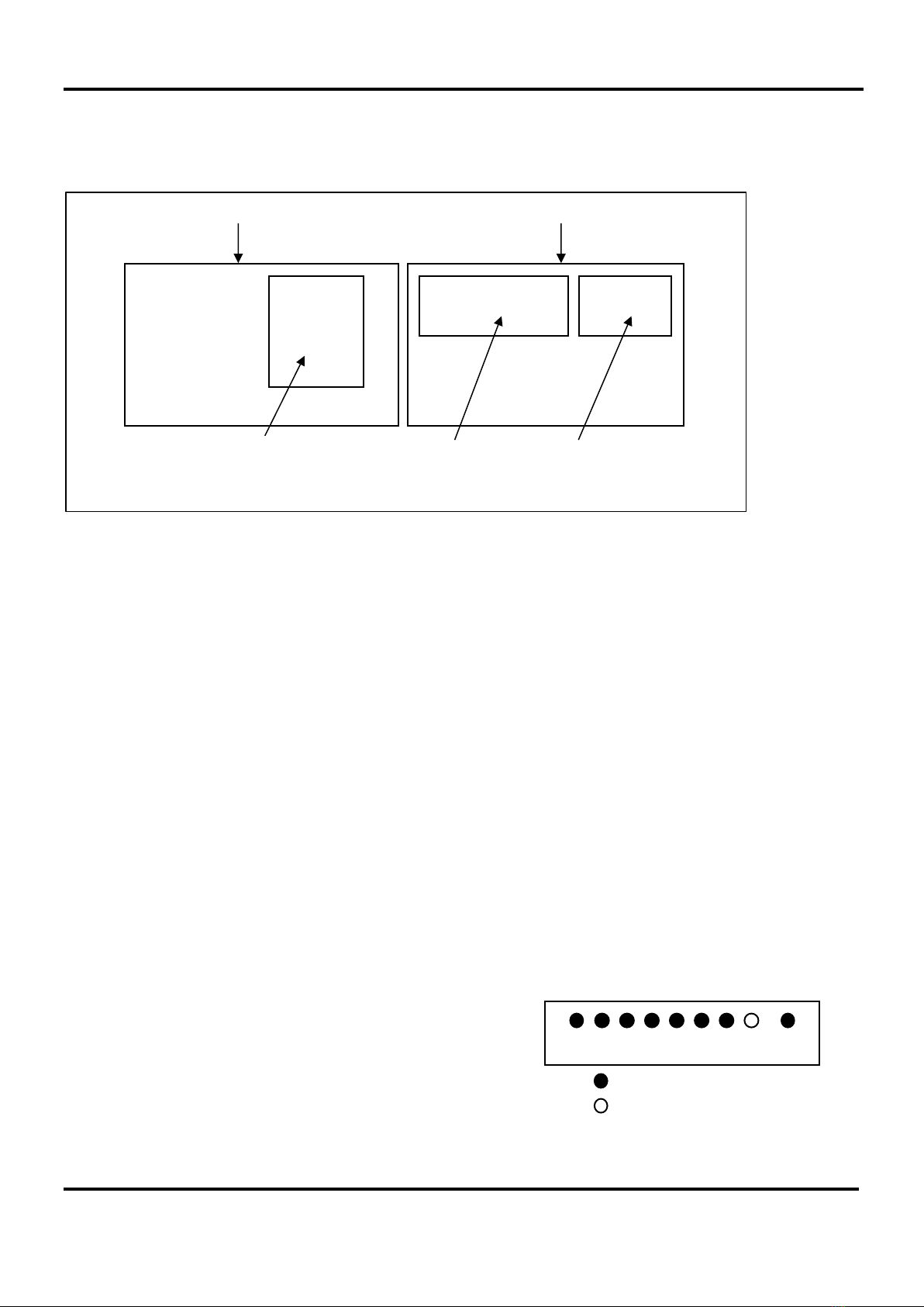
7 Mounting Enclosures
The MCU/LCU is supplied in a steel back-box with a hinged steel lid and several printed circuit boards (PCBs), as
shown below.
The MCU/LCU can be surface, or semi-flush mounted (maximum depth 60 mm including dimples). To expose the
base mounting holes the lid and PCBs must first be removed before installation. Before any of the following is carried
out ensure that the Mains power supply is isolated and the MCU/LCU batteries are removed.
7.1
Remove the base PCBs
Disconnect the cable from the Power Supply PCB to the Master Exchange PCB and the earth strap from the base
to the lid. Disconnect the earth strap spade connector from the main chassis earth point.
Carefully remove the PCB retaining screw located at the bottom left hand side of the Master Exchange and Power
Supply PCBs.
Push the PCB upwards and then pull forwards over the mounting pillars taking care not to damage any of the
components.
7.2
Remove the lid
Undo the two screws on the right hand side of the lid using the tool supplied.
Hinge the lid fully to the left. Unplug the earth strap and the two RJ45 plugs on the wiring looms. Carefully remove
the four M4 retaining nuts that secure the hinges.
The MCU/LCU lid and base PCBs should now be removed from site to prevent accidental damage.
Note: All PCBs are static sensitive and anti-static handling precautions MUST be observed when handling them.
7.3
Remove knockouts & cut gland holes
Mains should normally be brought into the base via a knockout
in the bottom right-hand corner. However, if top-entry is
required, it should enter through the knockout on the extreme
right. Cable segregation must be maintained.
If the MCU/LCU is fully populated with extensions then extra
20 mm holes may be cut in the top and rear, as required.
Note: This must be done before re-installation of PCBs to
avoid swarf getting into the electronics.
Power Supply PCB
Control PCB
MCU Hinged Lid MCU Back Box
Master Exchange PCB
MCU
Existing top knockouts
Extra 20 mm hole

SigTEL Compact Installation and Configuration Manual
SigTEL Approved Document No. DAU0000091 Rev 5 Page 13 of 36
Emergency Voice
Communication System
7.4
Fix the base to the wall
Using the four mounting holes, fix the base securely to the wall using suitable screw fixings. The mounting holes are
designed for No. 8 round-head, or countersunk wood-screws. Any dust, or swarf, must be kept out of the enclosure
and great care must be taken not to damage the wiring or components.

SigTEL Compact Installation and Configuration Manual
SigTEL Approved Document No. DAU0000091 Rev 5 Page 14 of 36
Emergency Voice
Communication System
7.5
Re-install the base PCBs
Re-install the base PCBs and refit the lid. Ensure the fixing screws and all interconnection cables are refitted
correctly, as shown below.
Cat 5 cables (supplied)
Engineer Mode
Reset
C
B
G
Conn 2
Conn 1
+ -
C
Power Supply lead
CAUTION: If re-connecting the
Power Supply lead, check that
the pins are not mis-aligned!
MCU internal connections
C
B
CAUTION: Double check all looms
are plugged into the correct ports!
C
B
G
Master Exchange PCB
MCU Lid MCU Back Box
G connects to
ECU722
(see Section 8).
Control PCB
Control
PCB
Master Exchange PCB
Power
Supply PCB
B
To Operator handset

SigTEL Compact Installation and Configuration Manual
SigTEL Approved Document No. DAU0000091 Rev 5 Page 15 of 36
Emergency Voice
Communication System
8 Installing the ECU722 Network Comms Card (Optional)
The MCU/LCU has a Master Exchange PCB and Power Supply PCB mounted in its base unit and a lid-mounted Control
PCB. The ECU722 card has to be mounted on top of the Master Exchange PCB. Before carrying out the steps below,
ensure that Mains power is isolated and the MCU/LCU batteries are disconnected.
Note: All PCBs are static-sensitive and therefore anti-static handling precautions MUST be observed when handling
them.
To install an ECU722 card follow the steps below:
1. Open the MCU/LCU lid by removing the two retaining lid screws (using an Allen key).
2. Disconnect the 10-way wiring loom between the Master Exchange PCB and the Power Supply PCB. Ensure
the loom remains connected to the Power Supply PCB to prevent it being misplaced.
3. Unplug the RJ45 connectors from terminals B&C
on the Master Exchange PCB. Ensure these
cables remain connected to the Control PCB to
prevent them being misplaced. Care should be
taken when detaching these connectors to
depress the locking tabs to prevent damage.
4. Unfasten the one retaining screw, located bottom
left side on the Master Exchange PCB, using a
crosshead screwdriver. Carefully slide the Master
Exchange PCB up and over its mounting pillars,
taking care not to damage any components.
5. Take the ECU722 card and carefully line up its
four holes with the holes in the Master Exchange
PCB, see right.
6. Insert four M3 x 15 mm slotted screws and hex
spacers (supplied) through the front holes in both
the ECU722 card and Master Exchange PCB so
they protrude through the back of the PCB. Next,
secure the ECU722 card and PCB together using
four M3 nuts (supplied), see right.
7. Refit the Master Exchange PCB (and mounted
ECU722 card) back into the base unit. Ensure the
retaining screw on the Master Exchange PCB is
firmly fastened down. Reconnect the RJ45 cables
and 10-way wiring loom.
8. Connect a Cat 5 cable (supplied) from terminal G
on the Control PCB to PL1 on the ECU722 card.
See below.
9. When all connections have been correctly made, re-connect power to the MCU/LCU.
CAT 5 cable (supplied)
ECU722
G
Control
PCB
Control PCB Power Supply PCB
Fitting the ECU722 card
MCU Lid
Master Exchange PCB
MCU
Back Box
ECU722
SigTEL Compact Installation and Configuration Manual
SigTEL Approved Document No. DAU0000091 Rev 5 Page 16 of 36
Emergency Voice
Communication System
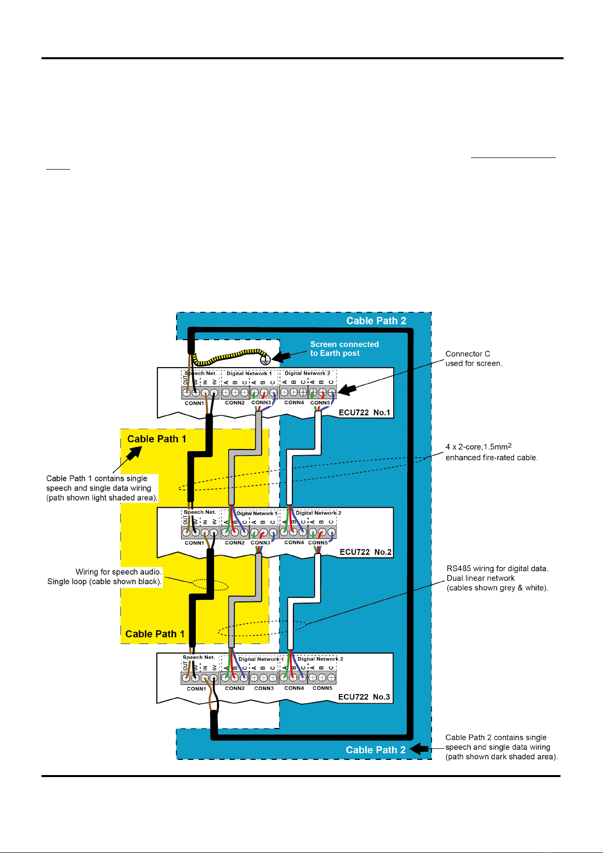
9 Network Connections (Optional)
The EVCS network allows up to 14 MCUs and LCUs to be connected by installing a Network Communications
Card (ECU722) in each unit.
The ECU722 card transmits speech audio via a single wiring loop and digital data via two linear RS485 networks
(Digital Networks 1 & 2). The network should be connected using 4 x 2-core, 1.5 mm2enhanced fire-rated cable.
Maximum length on the speech wiring loop, or digital linear wiring = 1 km. We recommend that two separate cable
paths be run with each path containing a single speech and single data cable which should not be mixed in the
same cable. MIXING SPEECH AND DIGITAL CABLES MAY CAUSE MAJOR PROBLEMS AND DEGRADE THE AUDIO SIGNAL!
A typical EVCS network showing three connected MCU/LCU units is shown below.
Speech loop wiring: ECU722 No.1 (Speech OUT/0V) to ECU722 No.3 (Speech IN/0V); ECU722 No.3 (Speech
OUT/0V) to ECU722 No.2 (Speech IN/0V); ECU722 No.2 (Speech OUT/0V) to ECU722 No.1 (Speech IN/0V).
Digital Network 1 wiring: ECU722 No.1 (Digital A/B/C) to ECU722 No.2 (Digital A/B/C); ECU722 No.2 (Digital
A/B/C) to ECU722 No.3 (Digital A/B/C).
Digital Network 2 wiring: Same wiring configuration as Digital Network 1.

SigTEL Compact Installation and Configuration Manual
SigTEL Approved Document No. DAU0000091 Rev 5 Page 17 of 36
Emergency Voice
Communication System
10 Mains Wiring
Connect Mains to the MCU/LCU
See BS 5839-9 section 13.
The MCU/LCU requires fixed wiring using 3-core enhanced fire-rated cable (no less than 0.75 mm2and no more
than 2.5 mm2) fed from an isolating switched fused spur, fused at 3 amps and MUST NOT be connected using a
plug and socket. The 230 VAC cable MUST enter the enclosure via one of the inlets at the bottom right hand corner
of the enclosure.
Ensure that Mains cables are kept as far away as possible from all other cables.
Mains supply should be exclusive to the EVCS. Circuit breakers supplying power to the system should be marked
‘EMERGENCY VOICE COMMUNICATION SYSTEM - DO NOT SWITCH OFF’.
A separate fused spur should be used for the MCU/LCU and should be marked ‘EMERGENCY VOICE
COMMUNICATION SYSTEM - DO NOT SWITCH OFF’.
See BS 5839-9 section 13.2 for more details.
Terminate the Mains input cable using the three-way plug supplied with the power supply PCB and ensure that
correct polarity is observed. The incoming Mains earth connection must be connected directly to the three-way plug
(P2) and NOT to the main chassis earth-point.
MCU/LCU mains connections
SigTEL Compact Installation and Configuration Manual
SigTEL Approved Document No. DAU0000091 Rev 5 Page 18 of 36
Emergency Voice
Communication System
11 Fitting Outstations & DPTA Interface
11.1
Cables
See section 4.
11.2
Location
See section 6.1.
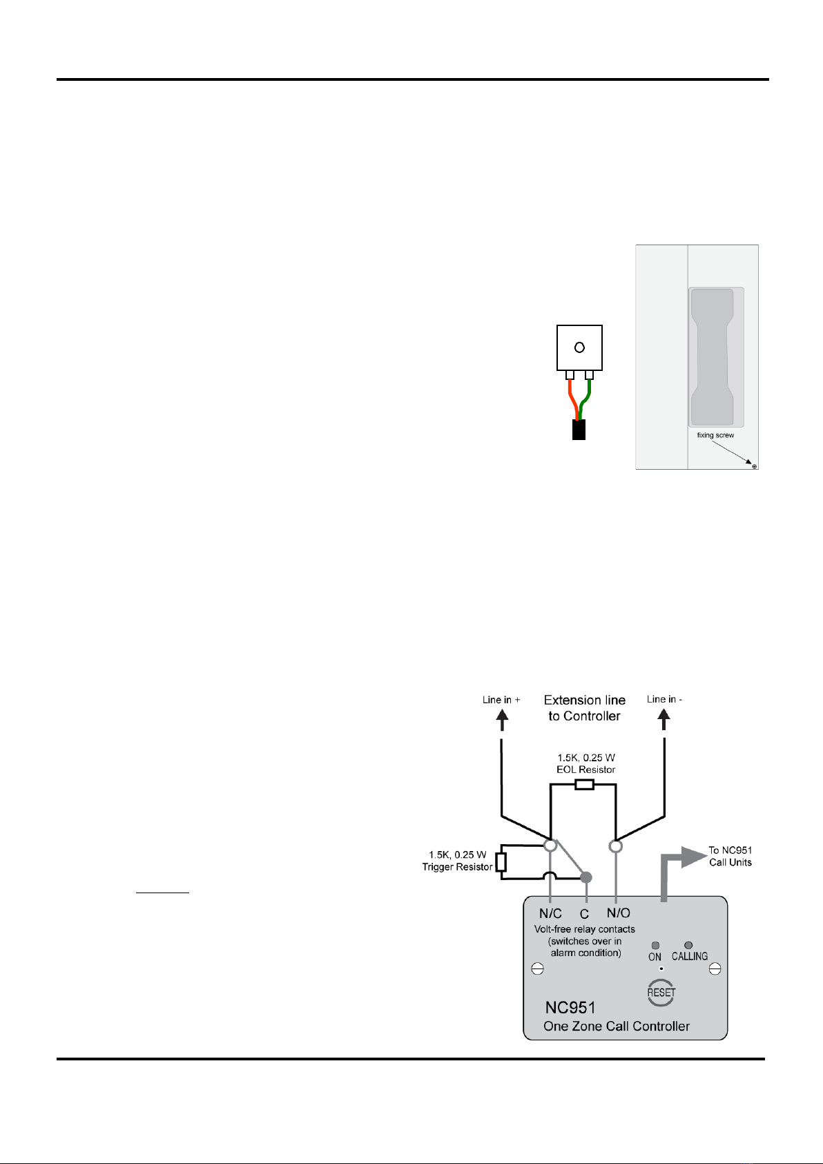
11.3
Fitting type A outstation (EVC301RPO/EVC301RLK)
Open the case and unscrew the fixing screw at the bottom of the unit and
remove the internal cover (see far right). This reveals the terminals and
earth stud. Fix to the wall, remove the knockout above the terminals and
fit a suitable cable gland. Connect the wires, as shown right.
For further details refer to Type A outstation instructions (DCM0003819).
11.4
Fitting type B outstation (EVC302S/GS and EVC302F/GF)
Type B outstations are supplied complete with a back box that should be fitted to the wall using suitable fasteners.
The back box has 20 mm knockouts at the top and bottom. Gland the cable correctly and connect a sleeved earth
wire to the earth stud.
Connect the line to the LINE IN + and LINE IN – terminals.
When installation is complete, secure the lid using the four machine screws. These have a secure pin-hex design
that requires a special Allen key (supplied).
For further details refer to Type B outstation instructions (DAU0302000).
11.5
Wiring to a disabled persons toilet alarm (DPTA)
To install the DPTA system, refer to the documentation supplied with the DPTA (Part No. NC951).
To interface the DPTA system to the EVCS, see wiring
diagram right. The NC951 has an on-board volt-free
relay.
Two 1.5k, 0.25 W, 10% resistors are supplied with the
NC951; the EOL resistor identifies the extension as a
DPTA and the trigger resistor when switched in, asserts
an active alarm on the EVCS.
Please note the stainless steel DPTA (Part No.
NC951/SS) does not have an on-board volt-free relay.
An additional 12 volt relay (Part No. NC883D) is
required to interface to the EVCS. Contact your supplier
for purchase information.
To MCU
Red +
Black
-
Red +
Green
-

SigTEL Compact Installation and Configuration Manual
SigTEL Approved Document No. DAU0000091 Rev 5 Page 19 of 36
Emergency Voice
Communication System
12 Testing Extensions
12.1
Insulation resistance testing
Insulation resistance testing should be carried out with no electronic devices
connected. Any devices connected to the extensions will be destroyed and will not
be covered by factory warranty.
12.2
The FiTT line tester
Note: See Specification (section 19) for component details.
Each extension should be tested prior to termination and connection to the Master
Exchange PCBs. We recommend that a SigTEL FiTT line tester is used to save time
proving the cables and outstations are working correctly.
It also avoids the need for Mains power testing.
If a FiTT line tester is not available, use a multimeter to check wiring for continuity
and correct polarity.
13 Second Fix Installation
13.1
Connecting extension s to t he MCU/LCU
Do not connect the extensions until they have been tested and are fault-free.
Bring each extension into the case via a suitable cable gland and connect to the terminals on the Master Exchange
PCB, as shown below. Master Exchange PCBs are fitted in the MCU/LCU.
Connect the screens to the earth terminal in the back of the case.
13.2
Fault monitoring
Once configured, the line fault monitoring system monitors for open and short circuits (absence of an outstation
constitutes open-circuit).
The MCU will also detect (and report a fault) if its handset is missing, e.g. the handset cord has been cut.

SigTEL Compact Installation and Configuration Manual
SigTEL Approved Document No. DAU0000091 Rev 5 Page 20 of 36
Emergency Voice
Communication System
13.3
Input connections
1. I/P A (Disable controls) – Disables Type A and Type B outstations.
2. I/P B (Disable controls) – Disables input signals from the DPTA.
In order to prevent unauthorized use of the system it is possible to disable the controls until an external trigger
is received, e.g. from a fire alarm control panel. I/P A & B are open-circuit, fail-safe system disablement inputs.
Closing these inputs (shorting the connections) disables the system so that the system can then be enabled
by opening the connections. No system configuration is required to use this facility and if they are left
unconnected it will operate normally.
Note: For a network system, only one MCU/LCU requires I/P A or I/P B wiring to the disablement source.
3. I/P C - Not currently used.
13.4
Output connections
1. Fault output - The terminals marked N/O, C and N/C
(see right) provide fail-safe fault outputs that can be
connected to a fire alarm panel or other monitoring
equipment.
The end-of-line device supplied with the input unit should
be connected at the MCU/LCU in order to monitor the
wiring (see example right). When a fault occurs the relay
disconnects the end-of-line device from the fire alarm
panel.
Note: For a network system, all MCU/LCU fault output
relays will be activated.
2. +24 V - Used to supply the output’s auxiliary equipment,
e.g. relays, etc.
3. OP1 output – activates whenever the master MCU is
ringing. Its main purpose is to provide an indication
(possibly remote), e.g. to a strobe, beacon, etc. when
someone is seeking assistance.
4. OP2 output – provides the equivalent function as OP1
output (above) for active toilet alarms.
5. OP3 output – closes when the handset is off hook and
remains active for 2 minutes after the handset is put
down. This function may be used to turn off noisy
equipment in the locality of the controller that may affect
communication.
Fault O/P
N/C
C
I/P +
End-of-line device
N/O Example use of Fault O/P
I/P -
N/O C N/C 0V +24V OP3 OP2 OP1
I/P A I/P B I/P C
+ - + - + -
OP1, 2 or 3
+ 24 V
Relay
coil
Example use of OP1, OP2, OP3
To protect the output stage, only 24V polarised
relays with back EMF diodes should be used
Table of contents
Popular Emergency Phone manuals by other brands


Talkaphone
Talkaphone VOIP-500 Series Quick installation guide

Lifemax
Lifemax Friends and Family Auto Dial quick start guide

Talkaphone
Talkaphone VOIP-500 Series installation guide

CareAlert
CareAlert SMART DIALLER Operation and instruction manual

CEECO
CEECO WPP-531-X Service manual

Hubbell
Hubbell GAI-TRONICS 297 manual