manuals.online logo
Brands
  1. Home
  2. •
  3. Brands
  4. •
  5. Wind Crest
  6. •
  7. Emergency Phone
  8. •
  9. Wind Crest ILO1 User manual

Wind Crest ILO1 User manual

1
Inductive Loop Systems
Low Power Inductive Loop: ILO1
Medium Power Inductive Loop: ILO 2 / 7
2
Introduction
An inductive loop amplifier is often used to improve the sound volume and
quality of sound to a person with a hearing aid. Under normal situations, the
hearing aid is set to pick up sound and amplify sound which is picked up by its
internal microphone and present it to the person who is wearing the hearing
aid. However, in a noisy environment or when the volume is low, the
amplification of sound picked up by the microphone may not be good enough.
To improve the general quality and volume of sound presented to the person
with a hearing aid, he would place the hearing aid in the “T position and pick
up the signal from an inductive amplifier.
The Inductive amplifier simply converts the audio sounds to a magnetic field
which is picked up by the hearing aid which there after reproduces the original
audio. This process tends to improve the sound quality and allows the hearing
aid wearer to adjust the volume to his requirement.
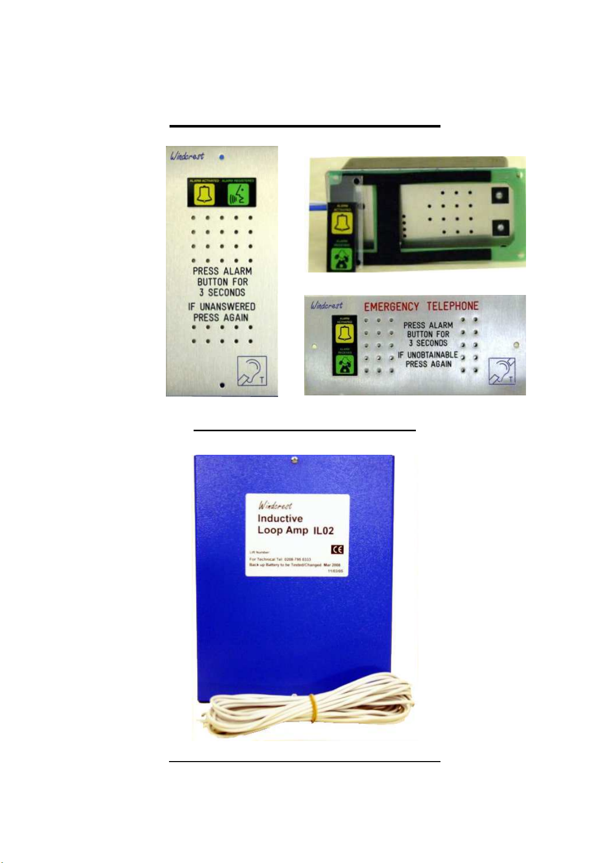
Windcrest has various Inductive Amplifiers which will produce the necessary
magnetic field which can be picked up by the heating aid. The range of
detection of the magnetic field is dependent on the amplifier power output and
the local environment; as ferrous magnetic materials tend to absorb magnetic
fields and reduce the effectiveness of the magnetic field.
Low Power Inductive Loop – ILO1 for Phone Line only
The standard speaker box, as used with a Windcrest Autodialler, can
accommodate a low power inductive amplifier which amplifies the sound on
the BT phone line. This amplifier is connected to a loop formed by the tracks
of a PCB, which in turn is sandwiched between the speaker box assembly
and the car operating face plate. On the basis that the face plate is made of a
non ferrous material, ie stainless steel, r nge of pproxim tely 300mm is
possible.
The IL01 is powered by the Windcrest Autodialler and hence it is battery
backed.
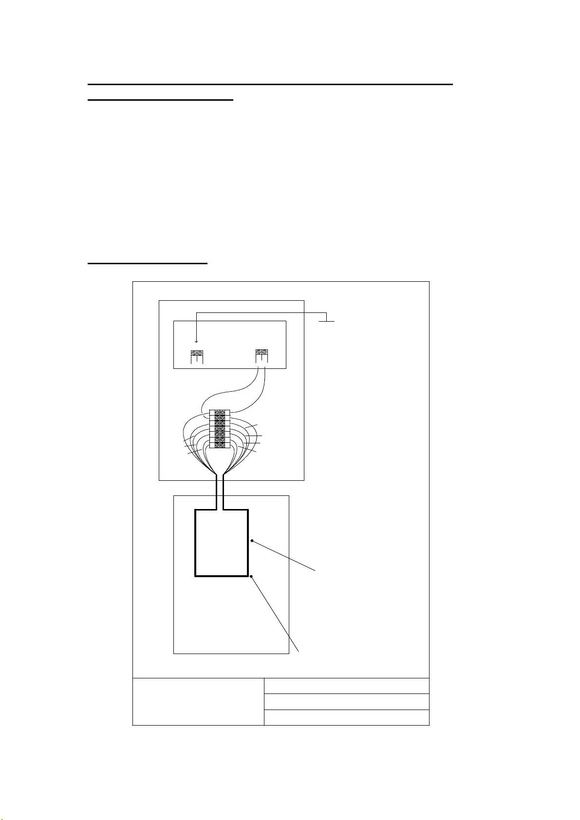
Inst ll tion of IL01
The installation of the IL01 consists of connecting the three wires to three
terminals on the Windcrest Main unit. (If Pictograms are used, the Inductive
loop amplifier will operate at the same time and no additional wiring is
required).
The cable interconnecting the main unit to the inductive loop should be as
short as possible or twisted screen cables must be used. Even thought screen
and twisted cable is used RFI interference may enter the inductive amplifier
and cause degradation in the strength of inductive signal and or distortion.
Additional filtering and isolating equipments such as INVERTER FILTER are
available to improve the situation.
3
4
Medium Power Inductive Loop – ILO7 for Phone line nd
Speech Synthesis unit
For applications where a greater coverage is required and where a speech
synthesis unit is installed, the IL07 solution is offered.
This unit is mains powered with battery back up and a higher current drive
capability. It can be connected to larger loops made of wire and there by
provide a more consistent magnetic field.
The unit uses a microphone mounted in the car operating panel not only to
pick up the audio from the BT Phone line but also from the speech synthesis.
(However, if a direct wired connection is required, the version IL07 will provide
this facility; Please call our technical department for assistance).
Inst ll tion of IL07
ILO x
Inductive Loop Board
Loop positioned on top of car,
side of car or in the floor of the
lift car. Any metallic object
around the loop will have a
significant effect on the
magnetic field of the loop. This
may reduce the range & cause
the field strength meters not to
register a level which is
acceptable. However acceptable
audio signals may still be picked
up by test meters which use
head phones.
Red
Red Black
Black
Black Blue
Blue Green
Green
Yellow Yellow
White
White Red
Windcrest (UK) Ltd Tel: 0208 795 0333
F x: 0208 795 0444
Loop using a 6 way cable
IL02 Inst ll tion
Drg No: IL02INST Issue No:2/P2 Date:30/01/05
LOOP
P
LOOP S
Note:
For larger installation where
there is a need for two loops,
use the S Loop terminals to
connect the secondary loop in
the same was as the primary
loop.
NB: Having two loops may result
in a reduction in the signal
strength of the primary loop, if
this happens reverse the wires
of the secondary loop.
Connect the Loop wires
(Red and Black) to the
boards Primary or
secondary Loop output
connector
(SLoop or PLoop)
This wire has no polarity
so Red and Black wires
are exchangeable.
5
Ex mples showing Loop Wire inst ll tion for full lift cover ge
Wind crest
PRESS ALARM
BUTTON FOR
3 SECONDS
IF UNOBTAINABLE
PRESS AGAIN
C r
Oper ting
P nel
Microphone
Medium Power
Induction
Loop ILO2
C r Top
Loop
Windcrest Tel: 0208 795 0333
F x: 0208 795 0444
DATE: 11/04/06
Ex mples of ILO2 Inst ll tion
Drawing: ILO2 Installation Examples Revision 1.0
Wind crest
PRESS ALARM
BUTTON FOR
3 SECONDS
IF UNOBTAINABLE
PRESS AGAIN
C r
Oper ting
P nel
Microphone
Medium Power
Induction
Loop ILO2
C r Top
Loop
Wind crest
PRESS ALARM
BUTTON FOR
3 SECONDS
IF UNOBTAINABLE
PRESS AGAIN
C r
Oper ting
P nel
Medium Power
Induction
Loop ILO2
C r Top
Loop
Windcr est
PRESS ALARM
BUTTON FOR
3 SECONDS
IF UNOBTAINABLE
PRESS AGAIN
C r
Oper ting
P nel
Medium Power
Induction
Loop ILO2
C r Top
Loop
Induction Loop mounted on Top of C r Induction Loop mounted behind COP
Induction Loop mounted round Lift C r Induction Loop mounted behind Lift C r
Microphone Microphone
6
Testing the Inductive Loop system
As mentioned, the inductive loop amplifiers produce the magnetic field which
corresponds to the sound. The ILO7 system has a facility to djust volume in
case distortion is encountered in the speech. Adjust the volume so that the
LED on the board just starts flickering when speech is on.
Microphone
Volume
BT Volume
Speech Synthesis
Volume
Pre-Amp
Volume Controls
Overall Amp
Volume
7
Various test units are available which provided a means of testing the
effectiveness of the loop.
Audio Pick up Unit
A test unit which acts like a hearing aid and simply coverts the
magnetic field into sound which is played through a pair of
headphones.
LED indicator type
A test unit which indicates the presence and the level of a magnetic
field by means of a set of LEDs. The general guide is to ensure there
is an average level of magnetic field which corresponds to 0dB.
However, the main thing is to ensure that the LED indicator responds
to speech rather than simply a steady level. (Electric motors, door gear
etc will produce a magnetic field and it may mask the speech from the
inductive loop).
Inductive Loop Field Strength Meters
8
Pre-testing of Inductive Loops (F ctory Test)
Prior to the dispatch of Inductive loops, each loop is tested with the Audio pick
up Unit in the factory with a preinstalled loop cable. Each system is check for
the strength/range. The low power inductive loop i.e. ILO1 covers a distance
of approx. 300mm from the Windcrest ILO1 Speaker box. The high power
inductive loop i.e. ILO2/7 can covers complete lift car provided the material
used in construction do not affect the magnetic field & considering the
microphone is place in a close proximity of the car speaker and proper
installation of loop cable (see installation example drawings).
During the final test, an audio pickup unit along with headphones are used to
check the functionality & strength of the signal. If the strength of the signal is
acceptable the unit is dispatched.
Post-testing of Inductive Loops (On-site Test)
Please follow the instructions on the previous pages for installation of
inductive loops. Once installation is complete the inductive loop system
should be check with either an audio pickup unit along with a pair of
headphones or with LED indicator unit.
In order to test an inductive loop system, the tester should be in the range of
inductive loop coverage area. The inductive loop test unit i.e. audio pickup or
LED indicator unit should be switched ON. At this point the tester should
trigger the autodialler unit by pressing the alarm button & wait for
announcement & audio communication. Audio signals which come out of the
speaker are transformed into magnetic field which will be picked up by the test
meters. In case of audio pickup unit the sound can be heard in the
headphones and in the LED indicator unit the LEDs will indicate the strength
of signal in dbs.
9
ILO 1 Specification
Power
Supplied from Windcrest Autodialler
Inputs
Connected to Autodialler
Output
Type: Current Mode Peak 00 mAmp into Loop Resistance minimum loop resistance 2Ohms. Average 75 mAmp
Performance
Frequency Response: 300Hz – 3.4KHz + - 3dB
Distortion : Less than 0.6%
Dimensions
As per Windcrest Lift Car Speaker
ILO2/7 Specification
Power
230-240VAC Mains Amp (20mm Fuse)
Inputs
3 Inputs are available.
Input Impedance : 0K
Sensitivity : 200mV – 2.5VRMS balanced or unbalanced.
Microphones
Sensitivity : – 8 mV
Input Impedance : 0K
Output
Type: Current Mode Peak 4Amp into Loop Resistance minimum loop resistance 4Ohms. Average 3 Amps
Performance
Frequency Response: 60Hz – 2KHz + - 3dB
Distortion : Less than 0.4%
Dimensions
270mm X 65mm X 70mm
Wei ht
2.2KG
Declaration of Conformity
Related Standards:
BS7594 - Audio Frequency Induction Loop System
EN60 8-4 – Magnetic Field Strength in audio frequency induction loop systems for hearing aid purposes
Safety: EN 4 003:2008 Particular safety requirements for equipment to be connected to telecommunications
networks and/or a cable distribution system.
EN 60950- :2006 Information technology equipment safety. General requirements.
EMC:
EN 30 489- V .8. Electromagnetic compatibility for radio equipment and services common technical
requirements.
EN 550 6-2-3:2006 Radiated emission, Class B.
EN 55022:2006 Conducted emissions, Class B.
EN 6 000-3-2:2006+A2:2009 Harmonic current emissions Class A
EN 6 000-3-3:2008 Voltage changes fluctuations and flicker.
Quality Manager – Derek Williamson Date – 03- -2003
Windcrestliftbits Ltd, Unit 8, Abbey Manufacturing Estate, Mount Pleasant, Wembley HA0 NR

Popular Emergency Phone manuals by other brands

tell GSM easyAID Quick reference guide

tell

tell GSM easyAID Quick reference guide

Safeline SL3000 manual

Safeline

Safeline SL3000 manual

AUDIOLINE BIGTEL 50 ALARM PLUS operating instructions

AUDIOLINE

AUDIOLINE BIGTEL 50 ALARM PLUS operating instructions

Studer EXICALL NIT 960 Brief description

Studer

Studer EXICALL NIT 960 Brief description

MediPendant MED01 quick start guide

MediPendant

MediPendant MED01 quick start guide

Talkaphone ETP-MT installation instructions

Talkaphone

Talkaphone ETP-MT installation instructions

Talkaphone AOR Series Installation & operation manual

Talkaphone

Talkaphone AOR Series Installation & operation manual

GAI-Tronics PHP400 Installation and user guide

GAI-Tronics

GAI-Tronics PHP400 Installation and user guide

Talkaphone ETP-MT/R Series installation instructions

Talkaphone

Talkaphone ETP-MT/R Series installation instructions

Safeline MX3+ manual

Safeline

Safeline MX3+ manual

Numera PERS-4200X installation instructions

Numera

Numera PERS-4200X installation instructions

Instant Care IC 3000 manual

Instant Care

Instant Care IC 3000 manual

CVI ViAC-RTK Installation and operation manual

CVI

CVI ViAC-RTK Installation and operation manual

CEECO WPP-531-X-ADA Service manual

CEECO

CEECO WPP-531-X-ADA Service manual

TekTone Tek-CARE 550 Installation and operation manual

TekTone

TekTone Tek-CARE 550 Installation and operation manual

LogicMark CaretakerSentry 40911 Dealer set-up & programming instructions

LogicMark

LogicMark CaretakerSentry 40911 Dealer set-up & programming instructions

switel Powertel TF 52 operating instructions

switel

switel Powertel TF 52 operating instructions

Viking E-1600A series Technical practice

Viking

Viking E-1600A series Technical practice

manuals.online logo
manuals.online logoBrands
  • About & Mission
  • Contact us
  • Privacy Policy
  • Terms and Conditions

Copyright 2025 Manuals.Online. All Rights Reserved.