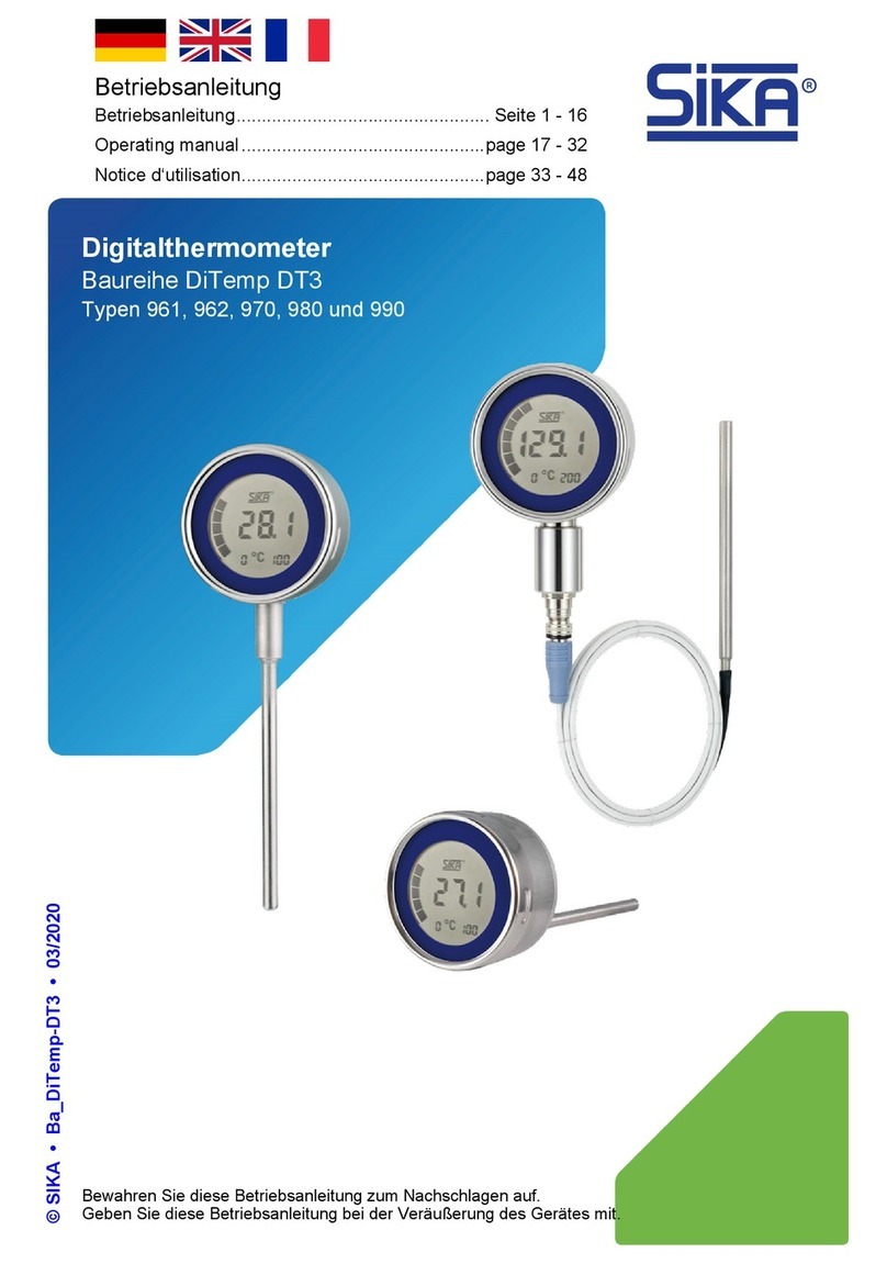
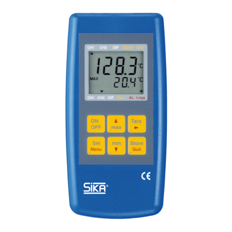
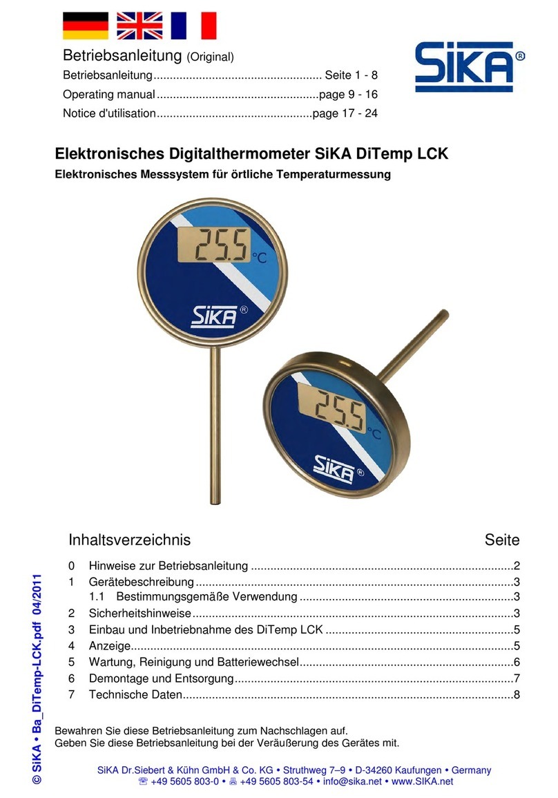
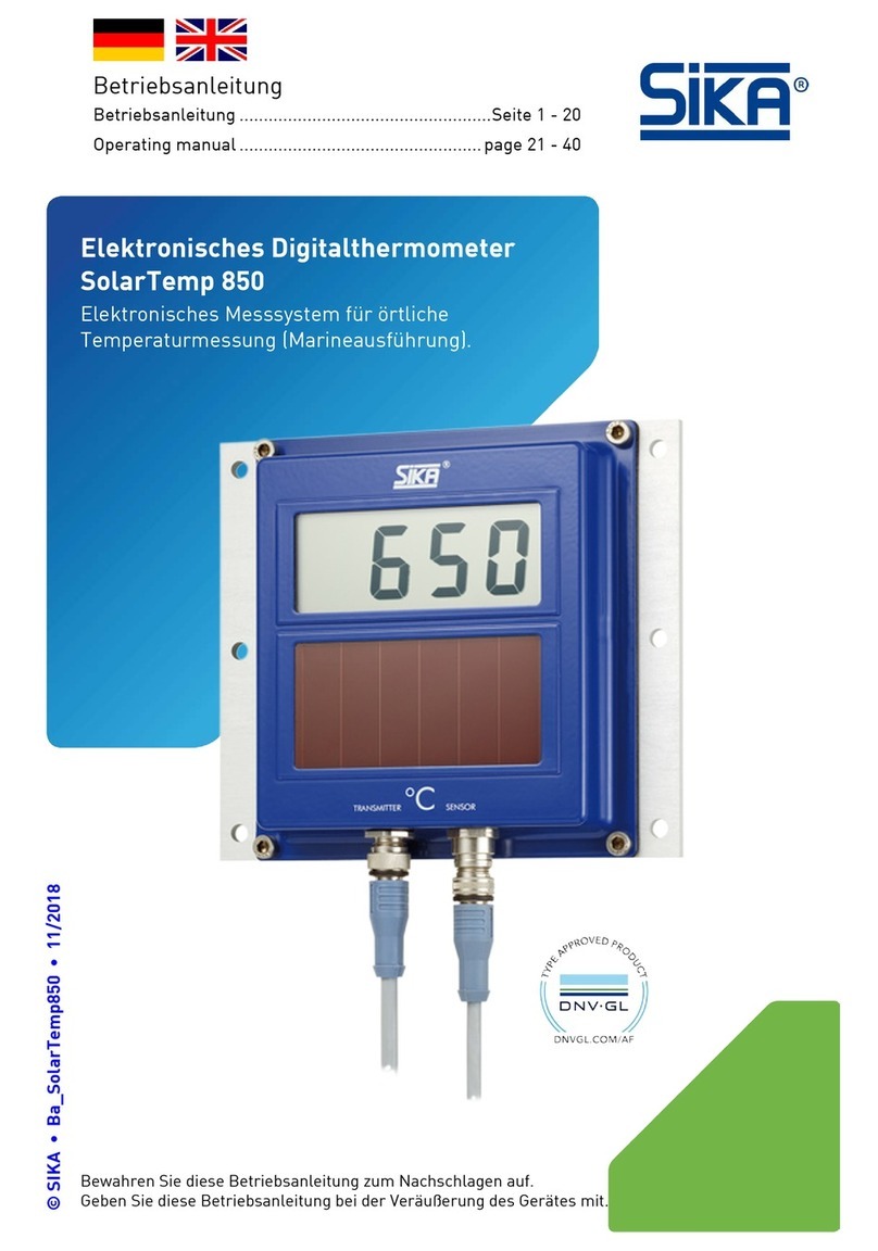
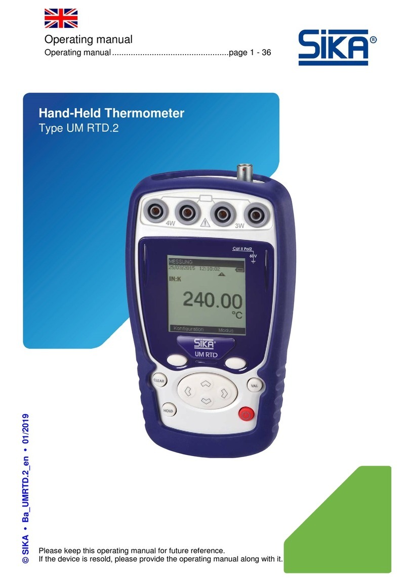
SIKA 621 User manual

Bewahren Sie diese Betriebsanleitung zum Nachschlagen auf.
Geben Sie diese Betriebsanleitung bei der Veräußerung des Gerätes mit.
© SIKA •Ba_ZT-BiMe •01/2015 .
Präzisions-Bimetall-Zeigerthermometer
Typen 621…681
Betriebsanleitung
(Original)
Betriebsanleitung
......................................................Seite 1 - 8
Operating manual
....................................................page 9 - 16
Notice d'utilisation
.................................................page 17 - 24

Bimetall-Zeigerthermometer
- 2 - © SIKA •Ba_ZT-BiMe •01/2015
Inhaltsverzeichnis Seite
0Allgemeines...................................................................................................................2
1Sicherheitshinweise ......................................................................................................3
2Beschreibung und Einsatz ............................................................................................3
3Technische Daten..........................................................................................................3
4Installation.....................................................................................................................4
5Bedienung......................................................................................................................6
6Wartung und Reparatur ................................................................................................7
7Außerbetriebnahme ......................................................................................................7
8Entsorgung ....................................................................................................................7
0Allgemeines
Bitte lesen Sie diese Betriebsanleitung vor der Inbetriebnahme des Gerätes.
Unsere Bimetall-Zeigerthermometer für industrielle Temperaturmessung werden in Über-
einstimmung mit der Norm DIN EN 13190 gefertigt.
Unsere Bimetall-Zeigerthermometer eignen sich zum Messen der Temperatur in Flüssigkei-
ten oder Gasen.
Verwendungen, die nicht ausdrücklich als bestimmungsgemäß aufgeführt werden,
sind bestimmungswidrig!
SIKA Dr. Siebert & Kühn GmbH & Co KG übernimmt keine Haftung für Schäden, die aus dem
unsachgemäßen Gebrauch des Gerätes bzw. durch Nichtbeachten der in dieser Betriebsan-
leitung enthaltenen Informationen entstehen.
Sollten Sie Probleme oder Fragen haben, wenden Sie sich an Ihren Lieferanten oder direkt
an:
Dr. Siebert & Kühn GmbH & Co. KG
Struthweg 7-9 • D - 34260 Kaufungen
05605-803 0 • 05605-803 54
info@sika.net • www.sika.net
Urheberschutzvermerk:
Weitergabe sowie Vervielfältigung dieser Betriebsanleitung, Verwertung und Mitteilung seines Inhalts
sind verboten, soweit nicht ausdrücklich gestattet. Zuwiderhandlungen verpflichten zu Schadenersatz.
Alle Rechte für den Fall der Patent
-, Gebrauchsmuster- oder Geschmacksmustereintragung vorbe-
halten.

Bimetall-Zeigerthermometer Sicherheitshinweise
Technische Änderungen vorbehalten - 3 -
1Sicherheitshinweise
Beachten Sie unbedingt die geltenden nationalen Sicherheitsvorschriften bei Montage,
Inbetriebnahme und Betrieb.
Der Anschluss darf nur von Fachpersonal ausgeführt werden.
Bei Nichtbeachten der entsprechenden Vorschriften können schwere Körperverletzungen
und/oder Sachschäden auftreten.
Sichern Sie einen zerstörungsfreien Einsatz Ihres Bimetall-Zeigerthermometers:
Die maximale Messstofftemperatur muss innerhalb des Anzeigebereichs des Gerätes lie-
gen.
Stellen Sie sicher, dass Bauausführung und Werkstoffe des Thermometers gegenüber
Einsatzbedingungen und Messstoff beständig sind.
Verwenden Sie Schutzrohre!
Thermometer ohne Dämpfungsflüssigkeit im Gehäuse sind für vibrations- und stoßfreie
Einsatzorte bestimmt.
Umbau oder sonstige technische Veränderungen des Gerätes durch den Kunden sind nicht
zulässig. Sie verlieren dadurch Ihren Garantieanspruch.
Für eine problemlose Montage und Demontage eignen sich Schutzrohre.
2Beschreibung und Einsatz
Unsere Bimetall-Zeigerthermometer besitzen Gehäuse und Fühler aus Edelstahl. Als Mess-
system dient eine Bimetallwendel.
Bei Temperaturänderungen rollt sich die Wendel auf. Diese Drehbewegung wird über eine
Achse direkt oder über eine Umlenkfeder auf den Zeiger übertragen.
Bimetall-Zeigerthermometer sind dadurch hysteresefrei. Sie eignen sich auch zur Messung
von aggressiven Messstoffen in der Chemie oder Petrochemie.
3Technische Daten
Bauformen:
Typ 621 Typ 631 Typ 681
Zur Kompensation des Einflusses von Vibrationen stehen Bimetallthermometer mit Gehäu-
sefüllung in gleichen Bauformen zur Verfügung.
Für die einzelnen Fühlertypen sind passende Schutzrohre lieferbar.

Installation Bimetall-Zeigerthermometer
- 4 - © SIKA •Ba_ZT-BiMe •01/2015
Anzeigebereich:
Der Messbereich Ihres Thermometers wird durch zwei Dreiecke auf der Skale gekennzeich-
net. Innerhalb dieser Grenzen ist die Genauigkeitsklasse 1 gewährleistet.
Aktive Länge der Fühler:
Die aktive Länge bestimmt die Mindestlänge des Fühlers. Sie richtet sich nach Anzeigebe-
reich (Temperaturdifferenz) und Fühlerdurchmesser.
ΔT
[K]
La [mm]
ø 6 mm
ø 8 mm
60
70
60
80
65
45
≥100
40
40
Weitere Informationen finden Sie in unseren Katalogen unter "kataloge.sika.net".
4Installation
Lagerung und Transport:
•zulässige Lagertemperatur: -40...+60 °C
mit Gehäusefüllung Glycerin: -20...+60 °C
•Bimetall-Zeigerthermometer müssen bei Transport und Lagerung vor mechanischen
Beschädigungen geschützt werden. Sie sind bis zum Gebrauch in der Originalverpackung
zu belassen.
•Die Verpackung kann als Altpapier entsorgt werden. Bei einem Weiter- oder Rücktrans-
port ist das Gerät ausreichend vor Beschädigungen zu schützen.
Montage:
Die Montage und Inbetriebnahme muss durch ausgebildetes, vom Betreiber autorisier-
tes Personal erfolgen.
Überprüfen Sie vor der Montage folgende Punkte:
Ist die Ware unbeschädigt und vollständig?
Stimmen Ware und Lieferpapiere überein?
Liegt das geeignete Gerät für den Einsatzfall vor?
Liegt die Prozesstemperatur innerhalb des Messbereiches?
Entspricht der Prozessanschluss den Anforderungen?

Bimetall-Zeigerthermometer Installation
Technische Änderungen vorbehalten - 5 -
Der mechanische Anschluss der Thermometer erfolgt gemäß den allgemeinen technischen
Regeln für die gewählte Verbindungsart.
Üben Sie beim Einschrauben des Thermometers keine Kraft über das Gehäuse aus. Halten
Sie drehbare Anschlusszapfen und Überwurfmuttern am Halsrohr gegen.
Für die Abdichtung zum Prozess bzw. zum Schutzrohr bei zylindrischen Verschraubungen
sind Dichtringe aus geeignetem Material (Standard: Aluminium- oder Messing-Dichtringe)
einzusetzen.
NPT-Verschraubungen (kegeliges Gewinde) dichten im Gewinde unter Zuhilfenahme geeig-
neter Dichtstoffe, z. B. PTFE- Band (Einsatztemperatur beachten!).
Zifferblatt und Zahlen sind senkrecht auszurichten. Bei Thermometern mit Gelenk Typ 681 ist
eine Verstellung des Gehäuses zur bestmöglichen Ablesung möglich.
Für ein genaues Ablesen ist das Gerät möglichst in Augenhöhe einzubauen.
Einbau des Temperaturfühlers:
Bauen Sie den Temperaturfühler so ein, dass der aktive Teil des Fühlers (aktive
Länge siehe Tabelle oben) vollständig vom Messstoff umspült wird.
Es entstehen Messfehler, wenn der aktive Teil des Fühlers unvollständig in den
Messstoff eintaucht.
Berücksichtigen Sie die Temperaturverteilung des Messstoffs an der Einbaustelle
des Thermometers. Vermeiden Sie die Messung zu nah an Wänden großer Behäl-
ter oder in Toträumen von Rohrleitungen, wenn dies nicht der eigentlichen Mess-
aufgabe entspricht.
Bei Verwendung von Schutzrohren kann der Wärmeübergangswiderstand zwischen Fühler-
außenwand und Schutzrohr-Innenwand durch Verwendung eines Wärmekontaktmittels re-
duziert werden.

Bedienung Bimetall-Zeigerthermometer
- 6 - © SIKA •Ba_ZT-BiMe •01/2015
5Bedienung
Der sichere Betrieb ist gewährleistet, wenn der Einbau ordnungsgemäß erfolgt ist.
Zum Ablesen gerade vor das in Augenhöhe montierte Thermometer treten und nicht schräg
oder seitlich schauen. Damit werden Ablesefehler vermieden.
Die Ablesegenauigkeit entspricht in der Regel dem Skalenteiler.
Umgebungstemperaturen:
Die zulässige Umgebungstemperatur gibt an, innerhalb welcher Temperaturgrenzen das
Thermometer ohne die Gefahr einer Beschädigung eingesetzt werden kann.
Innerhalb des Nenngebrauchbereiches wird die Fehlerklasse der Anzeige eingehalten.
Außerhalb des Nenngebrauchbereiches entstehen Temperaturzusatzfehler.
•zulässige Umgebungstemperatur: -40...+60 °C
mit Gehäusefüllung Glyzerin: -20...+60 °C
•Nenngebrauchsbereich: 23 ±5 °C
Verhindern Sie Personen und Sachschäden:
Beim Einrichten und Betreiben von Messstellen für gefährliche, brennbare, explosive
oder gesundheitsschädigende Stoffe müssen sämtliche geltenden Vorschriften einge-
halten werden.
Die Thermometer dürfen nicht über den Skalenendwert belastet werden. Das kann zur
Zerstörung führen.
Anzeigekorrektur:
Jedes Bimetall-Zeigerthermometer besitzt die Möglichkeit der Zeigerkorrektur (4% des An-
zeigebereiches).
Typen 621…681:
- Auf der Rückseite befindet sich eine Verstellschraube.
- Mit Hilfe eines Sechskantschlüssels SW 6 das Zifferblatt vorsichtig drehen, bis der Zeiger
auf Sollwert steht.
Führen Sie Anzeigekorrekturen nur durch, wenn Sie die Anzeige mittels Vergleichsmessung
überprüfen können. Als Vergleichsinstrumente verwenden Sie geeichte Glasthermometer
oder transportable, kalibrierte Digitalthermometer.

Bimetall-Zeigerthermometer Wartung und Reparatur
Technische Änderungen vorbehalten - 7 -
6Wartung und Reparatur
Bimetall-Zeigerthermometer sind wartungsfrei. Sie enthalten keine Elemente, die von Ihnen
ausgetauscht oder repariert werden können.
Zur Sicherstellung der Messgenauigkeit empfehlen wir, das Gerät regelmäßig zu überprüfen.
Durch Nachalterung kann nach ca. 1 Betriebsjahr eine Zeigerkorrektur notwendig werden.
Anfallende Reparaturen dürfen ausschließlich vom Hersteller durchgeführt werden.
Für eventuell notwendige Reparatur- oder Instandhaltungsarbeiten setzen Sie sich bitte mit
Ihrem Lieferanten oder unserem Werk in Verbindung. Das Gerät muss gut verpackt an unser
Werk gesandt werden (siehe oben).
Messstoffreste an ausgebauten Geräten können zur Gefährdung von Menschen, Umwelt
und Einrichtung führen. Ausreichende Vorsichtsmaßnahmen sind zu ergreifen.
7Außerbetriebnahme
Zur Außerbetriebnahme lösen Sie das Gerät bitte vollständig aus dem Einsatzbereich. Be-
achten Sie dabei die Hinweise unter Punkt 6.
8Entsorgung
Bitte helfen Sie mit, unsere Umwelt zu schützen und die verwendeten Werkstoffe ent-
sprechend den geltenden Vorschriften zu entsorgen bzw. der Wiederverwertung zuzu-
führen.

Please keep this operating manual for future reference.
If the device is resold, please provide the operating manual along with it.
© SIKA •Ba_ZT-BiMe •01/2015 .
Precision Bi-Metal Dial Thermometer
Types 621…681
Operating manual
(Translation)
Betriebsanleitung
......................................................Seite 1 - 8
Operating manual
....................................................page 9 - 16
Notice d'utilisation
.................................................page 17 - 24

Bi-Metal Dial Thermometer
- 10 - © SIKA •Ba_ZT-BiMe •01/2015
Table of contents page
0General ........................................................................................................................10
1Safety information .......................................................................................................11
2Description and use.....................................................................................................11
3Technical data .............................................................................................................11
4Installation...................................................................................................................12
5Operation .....................................................................................................................14
6Maintenance and repairs ............................................................................................15
7Removal from operation .............................................................................................15
8Disposal.......................................................................................................................15
0General
Please read these instructions for use before setting up the device to operate.
Our Bi-Metal Dial Thermometers for industrial temperature measurement are manufactured
in compliance with the DIN EN 13190 standard.
Our Bi-Metal Dial Thermometers are suited for measuring the temperature of liquids or gas-
es.
Applications which are not explicitly described as intended use are contrary to the in-
tended use!
SIKA Dr.Siebert & Kühn GmbH & Co KG assume no liability for damages arising from im-
proper use of the equipment or from disregard of the information contained in these instruc-
tions for use.
If you have any problems or questions, please contact your supplier or contact us directly at:
Dr. Siebert & Kühn GmbH & Co. KG
Struthweg 7-9 • D - 34260 Kaufungen
05605-803 0 • 05605-803 54
info@sika.net • www.sika.net
.
Copyright notice:
The reproduction, distribution and utilization of this operating manual as well as the co
m-
munication of its contents to others without express authorization is prohibited. Offenders
will be held liable for the payment of damages. All rights reserved in the event of the grant
of a patent, utility model or design.

Bi-Metal Dial Thermometer Safety information
Technical changes reserved - 11 -
1Safety information
Comply with the applicable domestic safety regulations during installation, operation-
al setup and use.
The connection must be made only by qualified personnel.
Disregard of the corresponding regulations can lead to severe bodily harm and/or property
damage.
Ensure that your Bi-Metal Dial Thermometer is used without damage by taking the follow-
ing precautions:
The maximum temperature of the medium to be measured must be within the display
range of the thermometer.
Check that the construction and materials of the thermometer are resistant to the condi-
tions of use and the medium to be measured.
Use thermowells!
Thermometers without damping fluid in the case are intended for use in locations free of
vibrations and impacts.
Conversions or other technical changes of the equipment by the customer are not permitted.
Such actions void the warranty.
Thermowells are suitable for trouble-free installation and removal.
2Description and use
Our Bi-Metal Dial Thermometer have a case and stem made of stainless steel. A bimetallic
coil is used as a measurement system.
As the temperature changes, the coil roll changes. This rotational movement is translated di-
rectly via an axle or via a deflection spring to the indicator.
This makes Bi-Metal Dial Thermometers free of hysteresis. They are also suited for measur-
ing corrosive chemical or petrochemical materials.
3Technical data
Models:
Type 621 Type 631 Type 681
To compensate for the influence of vibrations, Bi-Metal Dial Thermometers of the same de-
sign are available with case filling models.
Suitable thermowells are available for the individual stem types.

Installation Bi-Metal Dial Thermometer
- 12 - © SIKA •Ba_ZT-BiMe •01/2015
Display range:
The measuring of your thermometer is indicated by two triangles on the scale. Within these
limits accuracy class 1 is guaranteed.
Active Length of the stem:
The active length determines the minimum length of the stem. It is based on the display
range (temperature difference) and the stem diameter.
ΔT
[K]
La [mm]
ø 6 mm
ø 8 mm
60
70
60
80
65
45
≥100
40
40
More information can be found in our catalogues at "catalogues.sika.net".
4Installation
Storage and transport:
•Permitted storage temperature: -40...+60 °C
with glycerine filling of the case: -20...+60 °C
•Bi-Metal Dial Thermometers must be protected from mechanical damage during
transport and storage. They should be left in their original packaging until used.
•The packaging can be disposed of for paper recycling. In case of further transport or re-
turn, the equipment must be adequately protected from damage.
Installation:
Installation and setup for operation must be performed by trained personnel authorized
by the operating company.
Before installation, check the following:
Are the goods undamaged and complete?
Do the goods match the delivery documentation?
Is the device available suitable for the application?
Is the process temperature within the measuring range?
Does the process connection meet the requirements?

Bi-Metal Dial Thermometer Installation
Technical changes reserved - 13 -
The mechanical connection of the thermometer is made according to the general technical
guidelines for the selected connection type.
When screwing in the thermometer, do not exert force via the case. Hold up turnable thread-
ed nuts and union nuts at the stem.
For sealing to the process or thermowell with cylindrical threads, sealing rings made of suit-
able material (standard: aluminium or brass sealing rings) are to be used.
NPT couplings (tapered thread) seal in the thread using suitable sealing materials such as
PTFE tape (take note of the process temperature!).
The dial and numbers are to be aligned vertically. For thermometers with the joint Type 681, ad-
justment of the case for best readability is possible.
To facilitate exact reading, install the equipment at eye level if possible.
Installing the Stem:
Install the thermometer stem so that the active part of the stem (see the table
above for information on active length) is completely immersed in the medium to
be measured.
Errors in measurement will occur if the active part of the stem is not completely
surrounded by the medium to be measured.
Consider the temperature distribution of the medium at the place where the
thermometer is installed. Avoid measuring too close to walls of large tanks or in
dead spaces of piping if this is not the actual intent of measurement.
When using thermowells, the resistance to heat transfer between the outer wall of the stem
and the interior wall of the thermowell can be reduced by using a thermal contact medium.

Operation Bi-Metal Dial Thermometer
- 14 - © SIKA •Ba_ZT-BiMe •01/2015
5Operation
Safe and reliable operation is ensured with proper installation.
Stand straight in front of the thermometer installed at eye level to read it, not at an angle or
to the side. This will avoid reading errors.
The reading precision generally corresponds to the scale graduation.
Ambient temperatures:
The permitted ambient temperature indicates the limits within which the thermometer can
be used without the risk of damaging it.
The accuracy class of the indication is maintained within the nominal usage range.
Outside the nominal usage range additional temperature errors will occur.
•Permissible ambient temperature: -40...+60 °C
with case filling glycerine: -20...+60 °C
•Nominal usage range: 23 ±5 °C
Prevent personal injury and property damage:
Comply with all relevant regulations when setting up and operating measurement
points for materials which are dangerous, flammable, explosive or harmful to health.
The thermometers must not be used beyond the full scale value. Doing so can lead to
the destruction of the equipment.
Display correction:
Every Bi-Metal Dial Thermometer has the option to correct an indication error (4% of the
temperature range).
Types 621…681:
- There is an adjustment screw on the back side.
- Use a no. 6 hexagon Allen key to turn the dial carefully until the pointer is at the target val-
ue.
Correct indication errors only if you can check the accuracy by means of comparative meas-
urement. Instruments for comparison to use are calibrated glass thermometers or portable,
calibrated digital thermometers.

Bi-Metal Dial Thermometer Maintenance and repairs
Technical changes reserved - 15 -
6Maintenance and repairs
Bi-Metal Dial Thermometers requires no maintenance. It contains no elements which you
can replace or repair.
To ensure measurement accuracy, we recommend checking the equipment on a regular ba-
sis. After about a year of operation, correction of the indication may be necessary due to ag-
ing.
Incidental repairs must be made only by the manufacturer.
If repair or maintenance is necessary, please contact your supplier or our factory. The
equipment must be well packaged before sending it to our factory (see above).
Media residues on equipment which has been removed can pose a hazard to people, the
environment and property. Take appropriate precautionary measures.
7Removal from operation
To take the equipment out of operation, please remove it completely from the area of use.
Note the information provided in Section 6.
8Disposal
Please help to protect our environment and dispose of the materials used in accordance
with the applicable regulations or recycle them.

Conservez cette notice d'utilisation pour vous y reporter.
Joignez cette notice d'utilisation à la vente de l'appareil.
© SIKA •Ba_ZT-BiMe •01/2015 .
Thermomètre bimétallique à cadran
de précision
Types 621…681
Notice d'utilisation
(Traduction)
Betriebsanleitung
......................................................Seite 1 - 8
Operating manual
....................................................page 9 - 16
Notice d'utilisation
.................................................page 17 - 24

Thermomètre bimétallique à cadran
- 18 - © SIKA •Ba_ZT-BiMe •01/2015
Sommaire Page
0Généralités ..................................................................................................................18
1Consignes de sécurité.................................................................................................19
2Description et utilisation .............................................................................................19
3Données techniques....................................................................................................19
4Montage .......................................................................................................................20
5Fonctionnement ..........................................................................................................22
6Entretien et nettoyage.................................................................................................23
7Mise hors service ........................................................................................................23
8Elimination...................................................................................................................23
0Généralités
Avant de mettre en service le thermomètre bimétallique à cadran de précision, veuillez lire le
présent mode d'emploi.
Nos Thermomètre bimétallique à cadran pour la mesure industrielle de la température sont
fabriqués en accord avec la norme DIN EN 13190.
Nos Thermomètre bimétallique à cadran sont adéquats pour la mesure de la température
dans les liquides ou gazes.
Utilisations qui ne figurent pas explicitement comme prévu, doivent être considérées
comme incorrectes !
SIKA Dr. Siebert & Kühn GmbH & Co KG n'accepte aucune responsabilité pour les dommages
qui sont créés à partir de l'utilisation abusive de l'appareil ou par le non-respect des infor-
mations contenues dans cette notice d'utilisation.
Si vous avez des problèmes ou des questions, adressez-vous à votre fournisseur ou directe-
ment à :
Dr. Siebert & Kühn GmbH & Co. KG
Struthweg 7-9 • D - 34260 Kaufungen
05605-803 0 • 05605-803 54
info@sika.net • www.sika.net
Note sur
la protection des droits d'auteur :
Toute communication ou reproduction de cette notice d'utilisation, toute exploitation ou communic
a-
tion de son contenu sont interdites, sauf autorisation expresse. Tout manquement à cette règle est i
l-
licite et expose son
auteur au versement de dommages et intérêts. Tous droits réservés pour le cas
de la délivrance d'un brevet, d'un modèle d'utilité ou d'un modèle de présentation.

Thermomètre bimétallique à cadran Consignes de sécurité
Sous réserve de modifications techniques - 19 -
1Consignes de sécurité
Respectez les règles de sécurité lors de l'installation, la mise en service et le fonc-
tionnement.
Le montage et la mise en service doivent être effectués uniquement par le personnel qualifié
Le non respect des règlements pertinents peut conduire à des blessures graves et / ou des
dommages matériels.
Assurez une utilisation non destructive de votre Thermomètre bimétallique à cadran :
La température maximale du matériau à mesurer doit être comprise dans la plage d'affi-
chage de l'appareil.
Veillez à ce que l'exécution et les matériaux du thermomètre résistent aux conditions
d'utilisation et au matériau à mesurer.
Utilisez des gaines de protection !
Les thermomètres sans liquide de suspension au sein du boîtier ne doivent être utilisés
que dans des lieux exempts de vibrations et de chocs.
Changements ou autre modification technique du produit par le client ne sont pas autorisés.
Ces actions annulent la garantie.
Pour le montage et démontage facile, les gaines de protection sont appropriées.
2Description et utilisation
Nos Thermomètre bimétallique à cadran ont un boitier et une sonde d'acier inoxydable. Une
bobine bimétallique est utilisée comme système de mesure.
Lors des changements de température, la bobine se change. Ce mouvement de rotation est
transmis directement par un axe ou par un ressort d'inversion à l'aguille.
Ainsi les thermomètres bimétalliques sont sans hystérésis. Ils sont également adéquats
pour la mesure des fluides agressifs dans l'industrie chimique ou pétrochimique.
3Données techniques
Types :
Type 621 Type 631 Type 681
Pour compenser l'influence des vibrations, les thermomètres bimétalliques du même type
sont disponibles avec les boitiers remplis.
Pour chaque type des sondes, les gaines de protection appropriées sont disponibles.

Montage Thermomètre bimétallique à cadran
- 20 - © SIKA •Ba_ZT-BiMe •01/2015
Plage d'affichage :
La plage de mesure de votre thermomètre est caractérisée par deux triangles sur l'échelle.
Dans ces limites, la classe de précision 1 est garantie.
Longueur active de la sonde :
La longueur active détermine la longueur minimale de la sonde. Cela dépend de la plage
d'affichage (différence de température) et le diamètre de la sonde.
ΔT
[K]
La [mm]
ø 6 mm
ø 8 mm
60
70
60
80
65
45
≥100
40
40
Plus d'informations peuvent être trouvées dans nos catalogues à catalogues.sika.net.
4Montage
Stockage et transport :
•Température de stockage autorisée : -40...+60 °C
avec boitier rempli de glycérine : -20...+60 °C
•Les Thermomètre bimétallique à cadran de précision doivent être protégés de tout
dommage pendant le transport et le stockage. Jusqu'au moment de leur utilisation, ils
doivent être conservés dans leur emballage d'origine.
•L'emballage peut être éliminé avec les vieux papiers. En cas de déplacement ou de re-
tour, l'appareil doit être suffisamment protégé contre les dommages.
Montage :
Le montage et la mise en service ne doivent être confiés qu'à un personnel formé à cet
effet et autorisé par l'exploitant.
Avant d'installer, vérifiez les points suivants :
Est la marchandise intacte et complète ?
Correspond la marchandise aux documents d'expédition ?
Est l'appareil approprié pour l'application ?
Est la température de processus dans la plage de mesure ?
Correspond le raccordement de processus aux exigences ?
This manual suits for next models
2
Table of contents
Languages:
Other SIKA Thermometer manuals

SIKA
SIKA DiTemp LCK User manual

SIKA
SIKA SolarTemp 850 User manual

SIKA
SIKA SolarTemp LC User manual

SIKA
SIKA DiTemp User manual

SIKA
SIKA SolarTemp 850 User manual

SIKA
SIKA SolarTemp User manual

SIKA
SIKA MH 3211 User manual

SIKA
SIKA MH 3750 User manual

SIKA
SIKA UM RTD.2 User manual

SIKA
SIKA DiTemp DT3 Series User manual