Siko MSK2000 Operation manual

MSK2000+MB2000 Datum 09.11.2009 Art.Nr. 81962 Änd. Stand 326/09 1
DEUTSCH
Sensordarstellungen sind exemplarisch und gültig
für alle Bauformen, sofern nicht gesondert be-
schrieben.
1. Gewährleistungshinweise
Lesen Sie vor der Montage und der Inbetriebnahme
dieses Dokument sorgfältig durch. Beachten Sie zu
Ihrer eigenen Sicherheit und der Betriebssicherheit
alle Warnungen und Hinweise.
Ihr Produkt hat unser Werk in geprüftem und be-
triebsbereitem Zustand verlassen. Für den Betrieb
gelten die angegeben Spezifikationen und die
Angaben auf dem Typenschild als Bedingung.
Garantieansprüche gelten nur für Produkte der
Firma SIKO GmbH. Bei dem Einsatz in Verbindung
mit Fremdprodukten besteht für das Gesamtsystem
kein Garantieanspruch.
Reparaturen dürfen nur im Werk vorgenommen
werden. Für weitere Fragen steht Ihnen die Firma
SIKO GmbH gerne zur Verfügung.
2. Identifikation
Magnetband: Das Magnetband ist durch eine fort-
laufende Bedruckung identifizierbar.
•
•
•
•
z.B. MSK2000-0023
Varianten-Nr.
Geräte-Typ
3. Mechanische Montage
Die Montage darf nur gemäß der angegebenen IP-
Schutzart vorgenommen werden. Das System muss
ggfs. zusätzlich gegen schädliche Umwelteinflüs-
se, wie z.B. Spritzwasser, Lösungsmittel, Staub,
Schläge, Vibrationen, starke Temperaturschwan-
kungen geschützt werden.
3.1 Montage Magnetband
Die Montage muss plan zur Montagefläche bzw. der
zu messenden Strecke erfolgen. Welligkeiten ver-
schlechtern immer die Messgenauigkeit.
Überall wo aufgrund unzureichender Befestigungsmöglichkeiten
keine geeignete Montage des Magnetbandes möglich ist, kann das
Magnetband in eine als Zubehör lieferbare Profilschiene (z.B. Typ
PS oder PS1) montiert werden. Dadurch entsteht eine kompakte
Magnetbandeinheit.
Aus technischen Gründen muss bei der Länge,
gegenüber der Messstrecke, ein Zumaß von min.
137mm berücksichtigt werden.
Achtung! Um optimale Verklebungen zu errei-
chen müssen alle antiadhäsiven Fremdsubstanzen
(Öl, Fett, Staub usw.) durch möglichst rückstands-
los verdunstende Reinigungsmittel entfernt wer-
den. Als Reinigungsmittel eignen sich u.a. Ketone
(Aceton) oder Alkohole, die u.a. von den Firmen
Loctite und 3M als Schnellreiniger angeboten wer-
den. Die Klebeflächen müssen trocken sein und es
ist mit höchstmöglichem Anpressdruck zu verkle-
ben. Die Verklebungstemperatur ist optimal zwi-
schen 20°C und 30°C in trockenen Räumen.
Tip! Bei Verklebung langer Bänder sollte die
Schutzfolie des Klebebandes über eine kurze Teil-
strecke abgezogen werden, um das Band zu fixie-
ren. Daraufhin erfolgt das Ausrichten des Bandes.
Nun kann über die restliche Länge die Schutzfolie
unter gleichzeitigem Andruck des Bandes seitlich
herausgezogen werden (als Hilfsmittel kann eine
Tapetenandrückwalze verwendet werden).
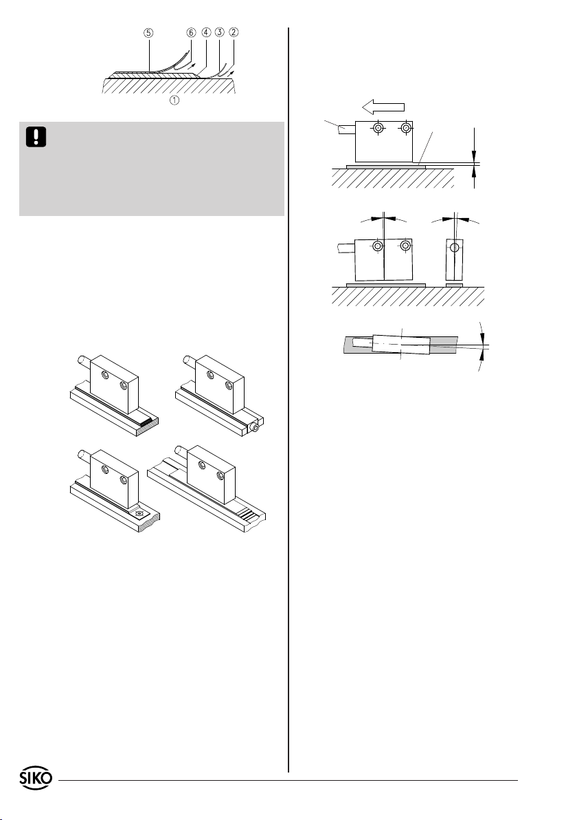
Montageschritte (Abb. 1)
Befestigungsfläche (1) sorgfältig reinigen.
Am Magnetband die Schutzfolie (2) des Klebe-
bandes (3) entfernen.
Magnetband (4) aufkleben.
Magnetbandoberfläche sorgfältig reinigen.
Am Abdeckband (5) die Schutzfolie (6) des Kle-
bebandes entfernen.
Abdeckband aufkleben (an beiden Enden leicht
überlappen lassen).
Die überlappenden Enden des Abdeckbandes gegen
Ablösen sichern.
•
•
•
•
•
•
•
Benutzerinformation
MSK2000+MB2000
Magnetsensor und Magnetband
Polbreite: 20mm
Bandgenauigkeit: 1mm
Seriennummer
1
0
0
NNNN 2000
Magnetsensor: Das Typenschild zeigt den Ge-
rätetyp mit Variantennummer. Die Lieferpapiere
ordnen jeder Variantennummer eine detaillierte
Bestellbezeichnung zu.
2 MSK2000+MB2000 Datum 09.11.2009 Art.Nr. 81962 Änd. Stand 326/09
Abb. 1: Montage Magnetband
Abb. 2 Abb. 3
Abb. 4 Abb. 5
Abb. 6: Definition der Zählrichtung / Montage
Zählrichtung A vor B
Kabelabgang Verfahrrichtung
aktive Seite
Abstand Sensor/Magnetband 1-10mm
±3° ±3°
±3°
maximale Fluchtungsfehler
Achtung! Die Beeinflussung durch magnetische
Felder ist zu vermeiden. Insbesondere dürfen keine
Magnetfelder (z.B. Haftmagnete oder andere Dau-
ermagnete) in direkten Kontakt mit dem Magnet-
band geraten. In stromlosem Zustand werden Be-
wegungen oder Verstellungen des Magnetsensors
von der Folgeelektronik nicht erkannt und erfasst.
Montagebeispiele
Die einfache Montageart, durch angeschrägtes
Schutzband (Abb. 2), ist nur in sehr geschützter Um-
gebung zu empfehlen. Bei ungeschützter Umgebung
besteht Abschälgefahr. In solchen Fällen sind Monta-
gearten, wie in Abb. 3 und 4 gezeigt, geeigneter.
Den optimalen Schutz bietet die Montage in einer
Nut (Abb. 5), die so tief sein sollte, dass das Magnet-
band vollständig darin eingebettet werden kann.
sowie Winkeltoleranzen beachten, diese müssen
über die gesamte Messstrecke eingehalten werden
(Abb. 6)!
Maximale Verfahrgeschwindigkeit <10m/s.•
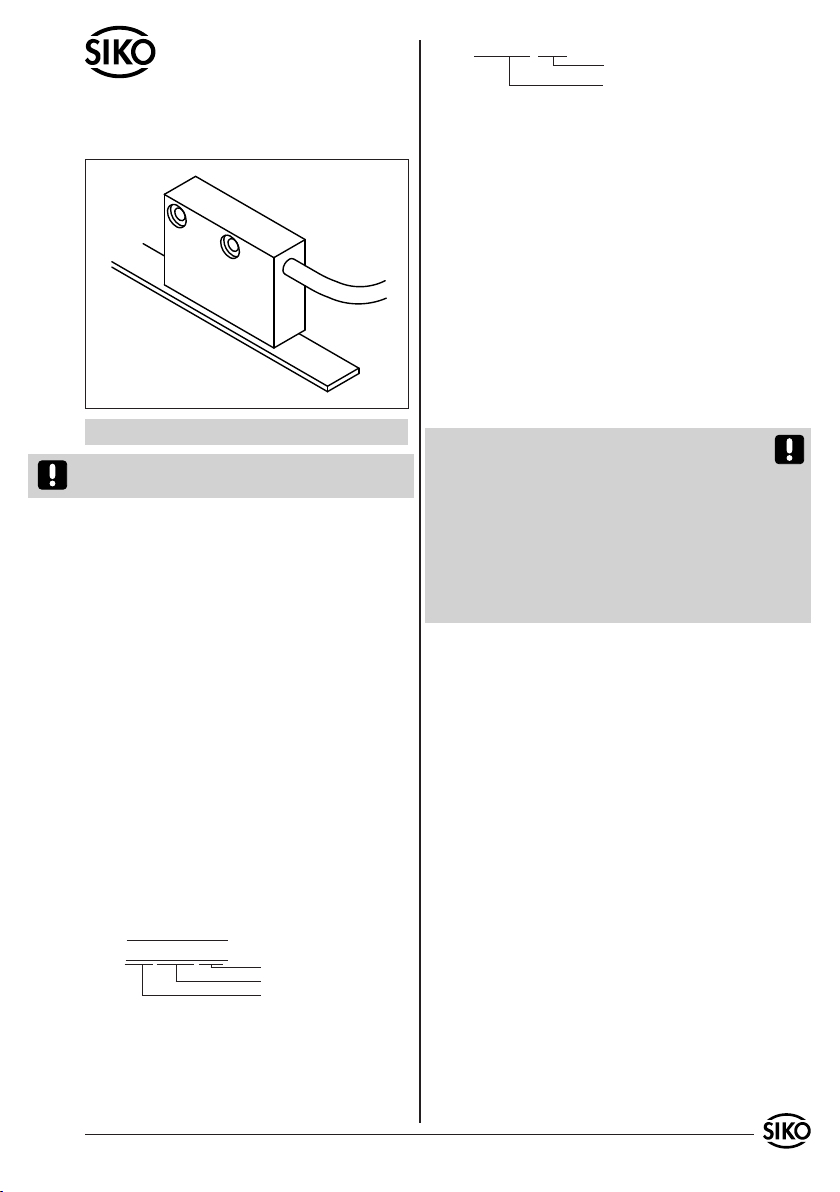
3.2 Montage Magnetsensor
Der Magnetsensor kann durch Verwendung von 2
Schrauben M3 über die ø3,5mm Durchgangslöcher
befestigt werden. Es wird empfohlen die beilie-
genden Befestigungsschrauben und Federringe zu
verwenden (Anzugsmoment 0,25Nm).
Kabel sind so zu verlegen, dass keine Beschädigungs-
gefahr durch Zug oder andere Maschinenteile besteht.
Falls nötig, Schleppkette oder Schutzschlauch
verwenden und Zugentlastung vorsehen.
Auf richtige Ausrichtung bezüglich der Zähl-
richtung achten (Abb. 6). Dies ist unerheblich
falls sich die Zählrichtung in der elektronischen
Auswertung umkehren lässt (wie z.B. bei den
Magnetbandanzeigen von SIKO).
Abstandmaße zwischen Sensor und Magnetband
•
•
•
4. Elektrischer Anschluss
Verdrahtungsarbeiten dürfen nur spannungslos
erfolgen!
Vor dem Einschalten sind alle Leitungsanschlüsse
und Steckverbindungen zu überprüfen.
Hinweise zur Störsicherheit
Alle Anschlüsse sind gegen äußere Störeinflüsse
geschützt. Der Einsatzort ist aber so zu wählen,
dass induktive oder kapazitive Störungen nicht
auf den Sensor oder dessen Anschlussleitung
einwirken können! Durch geeignete Kabelführung
und Verdrahtung können Störeinflüsse (z.B.von
Schaltnetzteilen, Motoren, getakteten Reglern
oder Schützen) vermindert werden.
Erforderliche Maßnahmen:
Nur geschirmtes Kabel verwenden. Den Kabel-
schirm beidseitig auflegen. Litzenquerschnitt der
Leitungen min. 0,14mm², max. 0,5mm².
Die Verdrahtung von Abschirmung und Masse (0V)
muss sternförmig und großflächig erfolgen. Der An-
schluss der Abschirmung an den Potentialausgleich
muss großflächig (niederimpedant) erfolgen.
Das System muss in möglichst großem Abstand von
Leitungen eingebaut werden, die mit Störungen
belastet sind; ggfs. sind zusätzliche Maßnahmen
•
•
•
•
•

MSK2000+MB2000 Datum 09.11.2009 Art.Nr. 81962 Änd. Stand 326/09 3
so kurz wie
möglich
Schirm
Abb. 7: Montage Anschlussart E6
Schirm
Buchsenteil
Stiftteil
Ansichtseite =
Steckseite
wie Schirmbleche oder metallisierte Gehäuse
vorzusehen. Leitungsführungen parallel zu Ener-
gieleitungen vermeiden.
Schützspulen müssen mit Funkenlöschgliedern
beschaltet sein.
Spannungsversorgung
Die Spannungswerte sind abhängig von der Sen-
sorausführung und sind den Lieferpapieren sowie
dem Typenschild zu entnehmen.
z.B.: 24 VDC ±20%
5. Anschlussarten
Die Steckerbelegungen der verschiedenen An-
schlussarten werden nachfolgend beschrieben.
Achtung! Die maximale Länge des Anschlusskabels
zwischen Sensor und Nachfolgeelektronik beträgt
20m.
Hinweis: Bei Betriebsspannung 24VDC und Aus-
gangsschaltung LD sind Abschlusswiderstände
≥470 Ohm zu verwenden, um thermische Überlas-
tung zu vermeiden.
Anschlussart E1
Anschluss mit offenen Kabelenden.
Achtung! Verzinnte Litzen dürfen nicht in Verbindung
mit Schraubklemmverbindungen eingesetzt werden.
Signal nicht
invertiert
invertiert invertiert mit
Referenzsignal
A rot rot rot
B orange orange orange
I - - - - - - blau
+UB braun braun braun
GND schwarz schwarz schwarz
A/ - - - gelb gelb
B/ - - - grün grün
I/ - - - - - - violett
Ummantelung entfernen.
Schirm auftrennen und verdrillen.
Litzen ca. 5mm abisolieren und verdrillen.
Aderendhülsen aufquetschen.
•
1.
2.
3.
4.
Signal nicht
invertiert
invertiert invertiert mit
Referenzsignal
A PIN 3 PIN 1 PIN 1
B 4 2 2
I - - - - - - 3
+UB 2 4 4
GND 1 5 5
A/ - - - 6 6
B/ - - - 7 7
I/ - - - - - - 8
- - - 5-7 3
Pos. 6 ... 10 über Kabelmantel schieben.
Kabel abisolieren.
Schirm umlegen.
Pos. 5 auf Litzen schieben.
Litzen an Pos. 3 löten (entspr. Anschlussplan).
Abstandhülse Pos. 4 aufweiten und über Litzen
stülpen, zusammendrücken und auf Pos. 3 ste-
cken. Schlitz und Nut (Pos. 3 und 4) müssen
deckungsgleich sein.
Pos. 6 an Pos. 5 drücken, überstehenden Schirm
abschneiden.
Pos. 2 und 7 aufschieben und mittels Montage-
werkzeug Pos. 11 verschrauben.
Pos. 8 in Pos. 9 stecken, beides in Pos. 7
schieben.
Pos. 10 mit Pos. 7 verschrauben.
Pos. 1 in Pos. 2 schieben.
1.
2.
3.
4.
5.
6.
7.
8.
9.
10.
11.
Anschlussart E6
Anschluss mit Kupplungsstecker und Kupplungsdo-
se. Steckermontage entsprechend Abb. 7.

4 MSK2000+MB2000 Datum 09.11.2009 Art.Nr. 81962 Änd. Stand 326/09
Abb. 8: Ermittlung der Polarität. Trennung des
Magnetbandes.
Abb. 9: Ermittlung der Polarität. Ansetzen des
Magnetbandes
6. Verlängern von Magnetbändern
Manche Anwendungsfälle können die Verlängerung
des Magnetbandes erfordern. Mit einfachen Hilfs-
mitteln besteht die Möglichkeit das Magnetband
zu trennen und wieder zusammenzusetzen.
Es ist jedoch selbst bei exakter Vorgehensweise
damit zu rechnen, dass die Genauigkeit an der
Trennstelle beeinträchtigt wird.
Hilfsmittel
Magnetlupe, -folie oder Metallstaub
Lineal oder geeignetes Werkzeug
Kompassnadel
•
•
•
7. Wartung
Die Oberfläche des Magnetbandes ist bei starker
Verschmutzung durch Staub, Späne, Feuchtigkeit,
usw., von Zeit zu Zeit mit einem weichen Lappen
zu reinigen.
8. Fehlerbehandlung
Typische Fehler, die bei Anbau und Betrieb auf-
treten:
Das Magnetband wurde falsch montiert /aktive
Seite nach unten (siehe Kap. 3.1).
Zum Schutz des Magnetbandes wurde nicht das
mitgelieferte Abdeckband verwendet. Das Abdeck-
band muss nichtmagnetisierbar sein.
Der Sensor ist nicht, oder nicht korrekt ange-
schlossen (Pinbelegung Kap. 5).
Die Abstandstoleranz zwischen Sensor und
Magnetband wurde nicht über die gesamte
Messstrecke eingehalten, der Sensor streift auf
dem Magnetband (Abb. 6).
Kabelunterbrechung / Abtrennung durch scharfe
Kanten / Quetschung.
Der Sensor ist mit der aktiven Seite vom Band
abgewandt montiert (Abb. 6). Die aktive Seite
ist zusätzlich mit dem Aufkleber "Bandseite"
gekennzeichnet.
Der Sensor wurde nicht entsprechend Abb. 6
ausgerichtet.
•
•
•
•
•
•
•
Vorgehensweise
Falls ein Abdeckband vorhanden ist, muss dieses
zuerst entfernt werden.
Polteilung durch Bestreuen des Magnetbandes
mit Metallstaub oder mit Hilfe einer Magnetlupe
oder Magnetfolie ermitteln.
Wenn erforderlich mit Kompassnadel kontrollie-
ren, wo sich die Pole am Magnetband befinden
(Abb. 8).
Lineal anlegen und Magnetband mit scharfem
Messer rechtwinklig abtrennen. Anschließend
auch Trägerband entsprechend kürzen.
Vorherige Schritte am anzusetzenden Band
wiederholen.
Vor dem Ansetzen die Polarität überprüfen.
Die beiden Enden müssen sich anziehen (ggfs.
Kompassnadel benutzen). Falls gleiche Polarität,
ein Band um einen halben Polabstand kürzen
(Abb. 8).
Beide Bänder stoßend montieren und Abdeckband
aufkleben.
•
•
•
•
•
•
•
MSK2000+MB2000 Datum 09.11.2009 Art.Nr. 81962 Änd. Stand 326/09 5
ENGLISH
Exemplary sensor illustrations are valid for all sen-
sor types unless described separately.
1. Warranty information
In order to carry out installation correctly, we
strongly recommend this document is read very
carefully. This will ensure your own safety and
the operating reliability of the device.
Your device has been quality controlled, tested
and is ready for use. Please observe all warnings
and information which are marked either directly
on the device or specified in this document.
Warranty can only be claimed for components
supplied by SIKO GmbH. If the units are used
together with other products, the warranty for
the complete system is invalid.
Repairs should be carried out only at our works.
If any information is missing or unclear, please
contact the SIKO sales staff.
2. Identification
Magnetic strip: identification by printing on the
strip.
•
•
•
•
e.g. MSK2000-0023
version number
type of unit
3. Installation
For mounting, the degree of protection specified
must be observed. If necessary, protect the unit
against environmental influences such as sprayed
water, dust, knocks, extreme temperatures, sol-
vents.
3.1 Mounting the magnetic strip
The mounting surface / measuring track must be
flat. Buckles or bumps will lead to measuring in-
accuracies.
For applications which do not allow properly glueing of the magne-
tic strip, it can be inserted into a profile rail (accessory) - eg. rail
type PS or PS1 thus forming a compact mounting unit.
For technical reasons the strip should be min.
137mm longer than the actual measuring distance.
Attention! To guarantee optimal adhesion oil,
grease dust etc. must be removed by using clean-
sing agents which evaporate without leaving re-
sidues. Suitable cleansing agents are eg. ketones
(acetone) or alcohols; Messrs. Loctite and 3M can
both supply such cleansing liquid. Make sure that
the surface to be glued is dry and apply the strip
with maximum pressure. Glueing should preferably
be undertaken at temperatures between 20°C to
30°C and in dry atmosphere.
Advice! When applying long pieces of magnetic
strip do not immediately remove the complete
protective foil, but rather peel back a short part
from the end sufficient to fix the strip. Now align
the strip. As the protective strip is then peeled
back and out press the tape firmly onto the moun-
ting surface. A wall paper roller wheel could be
used to assist in applying pressure onto the mag-
netic strip when fixing it in position.
Mounting steps (see fig. 1)
Clean mounting surface (1) carefully.
Remove protective foil (2) from the adhesive
side of the magnetic strip (3).
Stick down the magnetic strip (4).
Clean surface of magnetic strip carefully.
Remove protective foil (6) from adhesive tape on
the cover strip (5).
Fix cover strip (both ends should slightly over-
lap).
Also fix cover strip's ends to avoid unintenti-
onalpeeling.
•
•
•
•
•
•
•
User Information
MSK2000+MB2000
Magnetic sensor and magnetic strip
pole pitch: 20mm
accuracy: 1mm
serial number
1
0
0
NNNN 2000
Magnetic sensor: The particular type of unit and
type number can be seen from the identification
plate. Type number and the corresponding version
are indicated in the delivery documentation.
Other manuals for MSK2000
2
This manual suits for next models
1
Table of contents
Languages:
Other Siko Accessories manuals


