Siko MB500/1 Operation manual

MSK5000T+MB500/1+MR500 Datum 11.02.2016 Art.Nr. 84958 Änd. Stand 48/16 1
MSK5000T
MB500/1
MR500
DEUTSCH
1. Gewährleistungshinweise
• LesenSievorderMontageundderInbetriebnahme
diesesDokumentsorgfältigdurch.BeachtenSiezu
IhrereigenenSicherheitundderBetriebssicherheit
alle Warnungen und Hinweise.
• Ihr Produkt hat unser Werk in geprüftem und
betriebsbereitem Zustand verlassen. Für den
BetriebgeltendieangegebenSpezifikationenund
die Angaben auf dem Typenschild als Bedingung.
• Garantieansprüche gelten nur für Produkte der
Firma SIKO GmbH. Bei dem Einsatz in Verbindung
mitFremdproduktenbestehtfürdasGesamtsystem
kein Garantieanspruch.
• Reparaturen dürfen nur im Werk vorgenommen
werden. Für weitere Fragen steht Ihnen die Firma
SIKO GmbH gerne zur Verfügung.
2. Identifikation
Magnetband: Das Magnetband ist durch eine fort-
laufende Bedruckung identifizierbar.
Magnetsensor, Magnetring: Das Typenschild zeigt
den Gerätetyp mit Variantennummer. Die Lieferpa-
piere ordnen jeder Variantennummer eine detail-
lierte Bestellbezeichnung zu.
z. B. XXXXXXXX-0023
Varianten-Nr.
Gerät e-Typ
3. Mechanische Montage
Die Montage darf nur gemäß der angegebenen IP-
Schutzart vorgenommen werden. Das System muss
ggfs. zusätzlich gegen schädliche Umwelteinflüsse,
wie z. B. Spritzwasser, Lösungsmittel, Staub, Schlä-
ge, Vibrationen, starke Temperaturschwankungen
geschützt werden.
3.1 Montage Magnetband
Die Montage muss plan zur Montagefläche bzw. der
zu messenden Strecke erfolgen. Welligkeiten ver-
schlechtern immer die Messgenauigkeit.
Überall wo aufgrund unzureichender Befestigungs-
möglichkeiten keine geeignete Montage des Ma-
gnetbandes möglich ist, kann das Magnetband in
eine als Zubehör lieferbare Profilschiene (z. B. Typ
PS oder PS1) montiert werden. Dadurch entsteht
eine kompakte Magnetbandeinheit.
Aus technischen Gründen muss bei der Länge,
gegenüber der Messstrecke, ein Zumaß von min.
47mm berücksichtigt werden.
Achtung! Um optimale Verklebungen zu erreichen
müssen alle antiadhäsiven Fremdsubstanzen (Öl,
Fett, Staub usw.) durch möglichst rückstandslos
verdunstende Reinigungsmittel entfernt werden.
Als Reinigungsmittel eignen sich u. a. Ketone (Ace-
ton) oder Alkohole, die u. a. von den Firmen Loctite
und 3M als Schnellreiniger angeboten werden. Die
Klebeflächen müssen trocken sein und es ist mit
höchstmöglichem Anpreßdruck zu verkleben. Die
Verklebungstemperatur ist optimal zwischen 20°C
und 30°C in trockenen Räumen.
Tip! Bei Verklebung langer Bänder sollte die
Schutzfolie des Klebebandes über eine kurze Teil-
strecke abgezogen werden, um das Band zu fixie-
ren. Daraufhin erfolgt das Ausrichten des Bandes.
Nun kann über die restliche Länge die Schutzfolie,
unter gleichzeitigem Andruck des Bandes, seitlich
herausgezogen werden (als Hilfsmittel kann eine
Tapetenandrückwalze verwendet werden).
Montageschritte (Abb. 1)
• Befestigungsfläche (1) sorgfältig reinigen.
• Am Magnetband die Schutzfolie (2) des Klebe-
Benutzerinformation
MSK5000T Magnetsensor
MB500/1 Magnetband
MR500 Magnetring
Chargennummer
Referenzpunkt
Werksto-Trägerband
Genauigkeit
MB Typ
MBxxxx GEK WT RP NNNNNN

2 MSK5000T+MB500/1+MR500 Datum 11.02.2016 Art.Nr. 84958 Änd. Stand 48/16
Abb. 2 Abb. 3
Abb. 4 Abb. 5
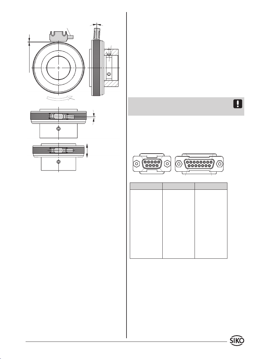
Abb. 6: Definition der Zählrichtung mit Magnetband
und Montage Sensor/Magnetband, Abstandsmaße,
Toleranzen
0.1 ... 2 mm
Abstand Sensor/Magnetband
Maximale Fluchtungsfehler
<1°
<3°
<3°
aktive Seite
Verfahrrichtung
Kabelabgangs-
richtung
Signal
A vor B
Zul. Abweichung
Mitte Band/
Sensor: ±2 mm
Abb. 1: Montage Magnetband
• Der Magnetring MR500 muss möglichst kraft-
und spannungsfrei montiert werden. Eventuell
erforderliche Belastungen sind am Metallflansch
aufzubringen. Schläge auf den Magnetring sind
zu vermeiden.
• Ein Wellenfreistich entsprechend Abb. 7 wird
empfohlen.
3.3 Montage Magnetsensor MSK5000T
Der Magnetsensor MSK5000T kann durch Verwen-
dung von 2 Schrauben M3 über die Langlöcher be-
festigt werden. Es wird empfohlen die beiliegenden
Befestigungsschrauben und Federringe zu verwen-
den.
• Kabel sind so zu verlegen, dass keine Beschädi-
gungsgefahr besteht. Zugentlastung und wenn
nötigSchleppketteoderSchutzschlauchvorsehen.
• Auf richtige Ausrichtung bezüglich der Zählrich-
tung achten (Abb. 6+7). Dies ist unerheblich
falls sich die Zählrichtung in der elektronischen
Auswertung umkehren läßt.
Achtung! Die Toleranz- und Abstandsmaße müssen
über die gesamte Messstrecke eingehalten werden.
Anwendung LINEAR MSK5000T mit MB500/1:
Achtung! Die Beeinflussung durch magnetische
Felder ist zu vermeiden. Insbesondere dürfen keine
Magnetfelder (z. B. Haftmagnete oder andere Dau-
ermagnete) in direkten Kontakt mit dem Magnet-
band geraten. In stromlosem Zustand werden Be-
wegungen oder Verstellungen des Magnetsensors
von der Folgeelektronik nicht erkannt und erfasst.
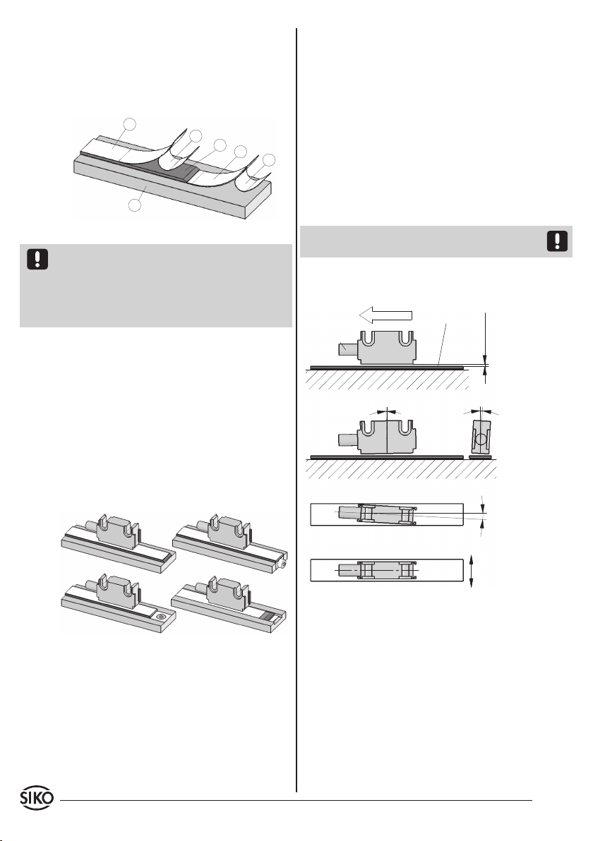
Montagebeispiele
Die einfache Montageart, durch angeschrägtes
Schutzband (Abb. 2), ist nur in sehr geschützter
Umgebung zu empfehlen. Bei ungeschützer Um-
gebung besteht Abschälgefahr. In solchen Fällen
sind Montagearten, wie in Abb. 3 und 4 gezeigt,
geeigneter.
Den optimalen Schutz bietet die Montage in einer
Nut (Abb. 5), die so tief sein sollte, dass das Ma-
gnetband vollständig darin eingebettet werden
kann.
bandes (3) entfernen.
• Magnetband (4) aufkleben.
• Magnetbandoberfläche sorgfältig reinigen.
• Am Abdeckband (5) die Schutzfolie (6) des Klebe-
bandes entfernen.
• Abdeckband aufkleben (an beiden Enden leicht
überlappen lassen).
• DieüberlappendenEndendesAbdeckbandesgegen
Ablösen sichern.
3.2 Montage Magnetring MR500
Nach dem Aufschieben des Magnetringes auf die
Welle, wird durch Anziehen des Gewindestiftes M6
der MR500 mit der Welle verbunden.
• Zwischen Welle und dem MR500 ist ein Schiebesitz
vorzusehen.
MSK5000T+MB500/1+MR500 Datum 11.02.2016 Art.Nr. 84958 Änd. Stand 48/16 3
Ansichtseite = Steckseite
Buchsenkontakt
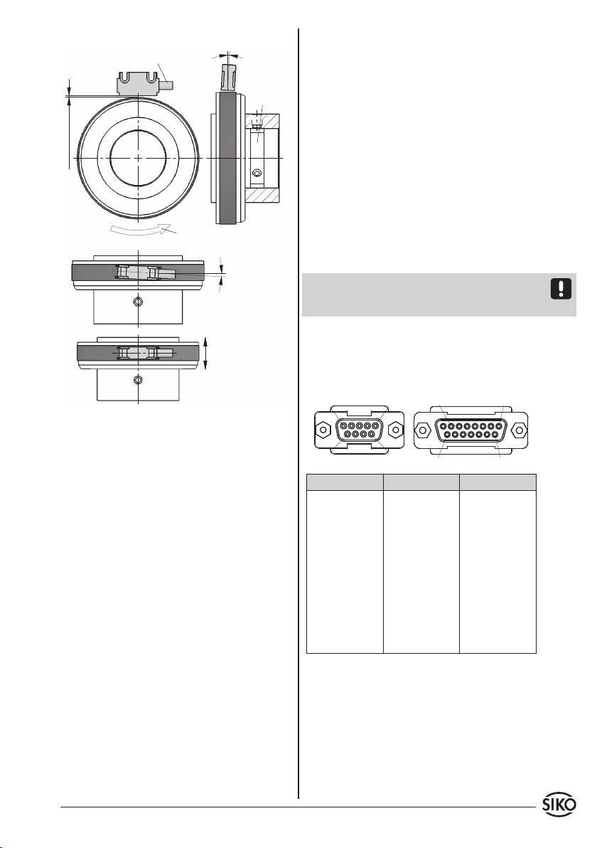
Abb.7: Definition der Zählrichtung mit Magnetring
und Montage Sensor / Magnetring, Abstandsmaße,
Toleranzen
<3°
<3° Freistich an
der Vollwel-
le für Gewin-
destift wird
empfohlen
Signal
A vor B Drehrichtung Magnetring
0.1 ... 2 mm
Kabelabgangsrichtung
Zul. Abweichung
Mitte Band/Sensor:
±2 mm
Anwendung RADIAL MSK5000T mit MR500:alausgleich muss großflächig (niederimpedant)
erfolgen.
• DasSystemmussinmöglichstgroßemAbstandvon
Leitungen eingebaut werden, die mit Störungen
belastet sind;ggfs. sind zusätzliche Maßnahmen
wie Schirmbleche oder metallisierte Gehäuse
vorzusehen. Leitungsführungen parallel zu Ener-
gieleitungen vermeiden.
• Schützspulen müssen mit Funkenlöschgliedern
beschaltet sein.
Spannungsversorgung
Die Spannungswerte sind abhängig von der Sen-
sorausführung und sind den Lieferpapieren sowie
dem Typenschild zu entnehmen.
z. B.: 5VDC
Achtung! Die maximale Länge des Anschlusskabels
zwischen Sensor und Nachfolgeelektronik beach-
ten.
4.1 Anschlussbelegung
Anschluss mit D-SUB Stecker.
4. Elektrischer Anschluss
• Verdrahtungsarbeiten dürfen nur spannungslos
erfolgen!
• Vor dem Einschalten sind alle Leitungsanschlüsse
und Steckverbindungen zu überprüfen.
Hinweise zur Störsicherheit
Alle Anschlüsse sind gegen äußere Störeinflüsse
geschützt. Der Einsatzort ist aber so zu wählen,
dass induktive oder kapazitive Störungen nicht
auf den Sensor oder dessen Anschlussleitung
einwirken können! Durch geeignete Kabelfüh-
rung und Verdrahtung können Störeinflüsse (z. B.
von Schaltnetzteilen, Motoren, getakteten Reglern
oder Schützen) vermindert werden.
Erforderliche Maßnahmen:
• Nur geschirmtes Kabel verwenden. Den Kabel-
schirm beidseitig auflegen. Litzenquerschnitt der
Leitungen min. 0.14 mm²; max. 0.5 mm².
• Die Verdrahtung von Abschirmung und Masse
(0V) muss sternförmig und großflächig erfolgen.
Der Anschluss der Abschirmung an den Potenti-
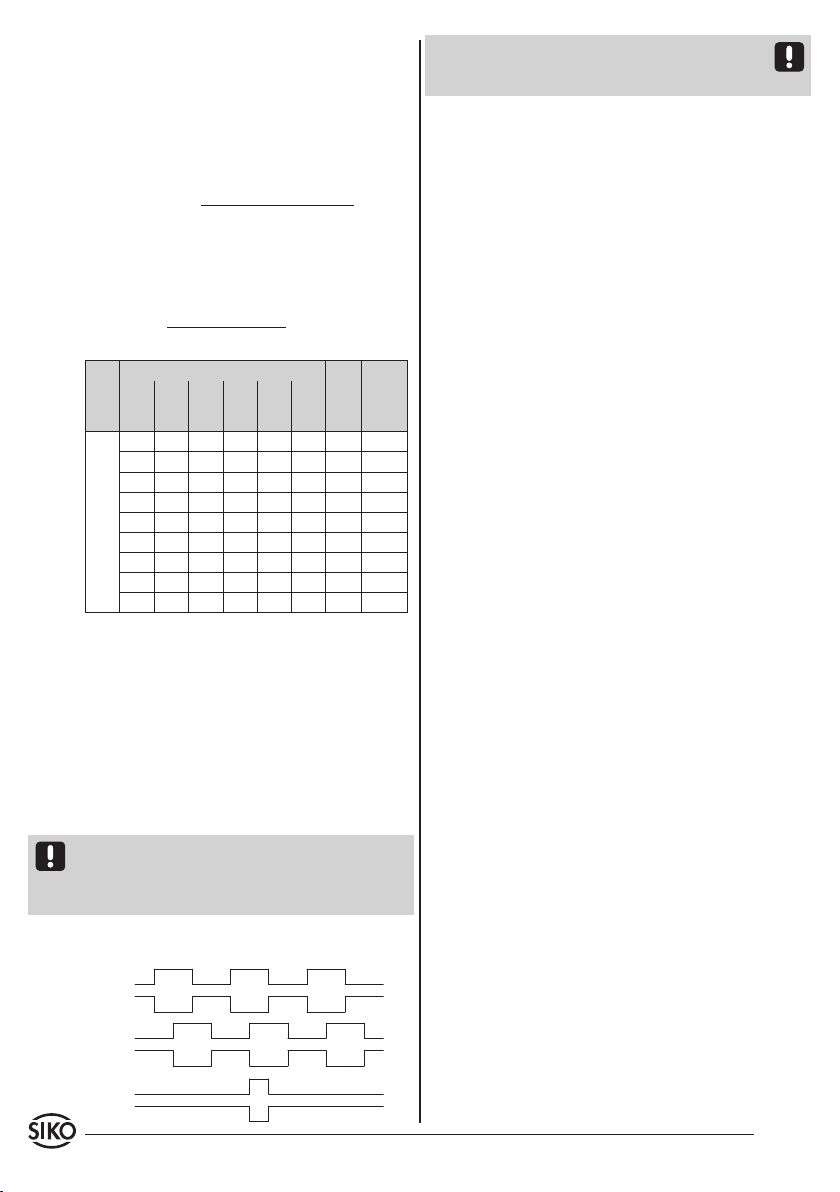
Pin 9-pol. Pin 15-pol. Signal
1 1 A
2 2 /A
3 3 GND (Signal)
4 4 B
5 5 /B
6 9 /I
7 10 I
8 6, 7, 8 +UB
9 12 GND (UB)
11, 13, 14, 15 nc
5. Inbetriebnahme
Nach ordnungsgemäßer Montage und Verdrahtung
kann das Messsystem durch Einschalten der Versor-
gungsspannung in Betrieb genommen werden.
Das Messsystem MSK5000T+MB500/1+MR500 ist
Bestandteil eines inkrementalen Messsystem, dass
zur absoluten Messung an einer definierten Stelle
(Referenzpunkt) referenziert werden muss. Dazu
4 MSK5000T+MB500/1+MR500 Datum 11.02.2016 Art.Nr. 84958 Änd. Stand 48/16
muss das Referenzsignal mit dem Signal eines Re-
ferenzwertgebers (z. B. Näherungsschalter) ver-
knüpft werden.
6. Verfahrgeschwindigkeiten (m/s)
Formel zur Berechnung der Verfahrgeschwindig-
keit:
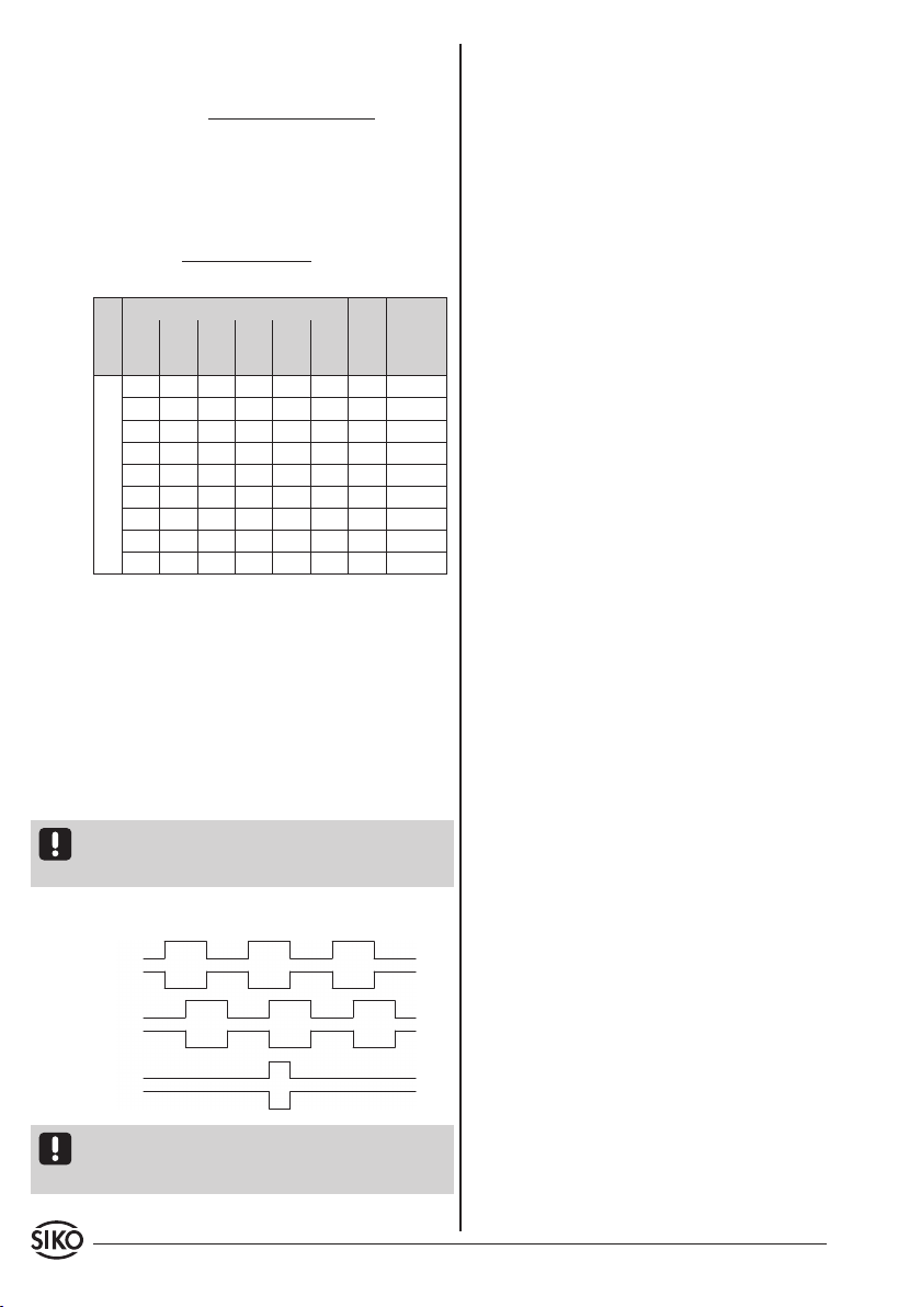
Hinweis: Die Lage des Indexsignals I zu den Si-
gnalen A und B ist nicht definiert und kann von der
Zeichnung abweichen.
8. Wartung
Die Oberfläche des Magnetbandes ist bei starker
Verschmutzung durch Staub, Späne, Feuchtigkeit
usw., von Zeit zu Zeit mit einem weichen Lappen zu
reinigen.
9. Fehlerbehandlung
Typische Fehler, die bei Anbau und Betrieb auftre-
ten:
• Das Magnetband wurde falsch montiert / aktive
Seite nach unten (siehe Kapitel 3.1).
• Zum Schutz des Magnetbandes wurde nicht das
mitgelieferteAbdeckbandverwendet.DasAbdeck-
band muss nicht magnetisierbar sein.
• DerSensoristnicht,odernichtkorrektangeschlos-
sen (Pinbelegung Kapitel 4.1).
• Die Abstandstoleranz zwischen Sensor und Ma-
gnetband/Magnetring wurde nicht eingehalten
(beim Band über die gesamte Messstrecke!), der
Sensor streift auf dem Magnetring (Abb. 6+7).
• Kabelunterbrechung / Abtrennung durch scharfe
Kanten / Quetschung.
• Der Sensor ist mit der aktiven Seite vom Band
abgewandt montiert (Abb. 6+7).
• Der Sensor wurde nicht entsprechend Abb. 6+7
ausgerichtet.
Beispiel:
Auflösung: 0.01 mm
Pulsabstand: 2.5 µs
Auflösung in mm
Pulsabstand
(µs)
Zählfrequenz
(kHz)
0.001 0.005 0.010 0.025 0.050 0.100
Verfahrgeschwindigkeit in m/s
0.01 0.06 0.12 0.30 0.61 1.21 66.00 3.79
0.03 0.13 0.25 0.63 1.25 2.50 32.00 7.81
0.05 0.25 0.50 1.25 2.50 5.00 16.00 15.63
0.10 0.50 1.00 2.50 5.00 10.00 8.00 31.25
0.20 1.00 2.00 5.00 10.00 20.00 4.00 62.50
0.32 1.60 3.20 8.00 16.00 25.00 2.50 100.00
0.80 4.00 8.00 20.00 25.00 25.00 1.00 250.00
1.60 8.00 16.00 25.00 25.00 25.00 0.50 500.00
4.00 20.00 25.00 25.00 25.00 25.00 0.20 1250.00
7. Ausgangssignale
Die Auswerteelektronik setzt die magnetischen
Längeninformationen des Magnetsensors in inkre-
mentale Ausgangssignale um. Die Ausgabe der Si-
gnale erfolgt geschwindigkeitsproportional.
Es ist zu beachten, dass im Stillstand Impulse von
der Breite des eingestellten Pulsabstandes auf-
treten können (bedingt durch das interne Interpo-
lationsverfahren).
Achtung! Bei der Dimensionierung der Nachfolgee-
lektronik ist zu beachten, dass diese für den einge-
stellten Pulsabstand bzw. Zählfrequenz ausgelegt
ist.
Signalfolge
V max. =
(in m/s)
Auflösung in mm
Pulsabstand in s x 1000 x 0.8
V = 0.1
0.0000025 x 1000 x 0.8 = 3.2m/s

MSK5000T+MB500/1+MR500 Datum 11.02.2016 Art.Nr. 84958 Änd. Stand 48/16 5
MSK5000T
MB500/1
MR500
ENGLISH
1. Warranty information
• In order to carry out installation correctly, we
strongly recommend this document is read very
carefully. This will ensure your own safety and the
operating reliability of the device.
• Yourdevicehasbeenqualitycontrolled,testedand
is ready for use. Please observe all warnings and
information which are marked either directly on
the device or specified in this document.
• Warranty canonly beclaimed for componentssup-
pliedbySIKOGmbH.If the system is used together
with other products, there is no warranty for the
complete system.
• Repairs should be carried out only at our works.
If any information is missing or unclear, please
contact the SIKO sales sta.
2. Identification
Magnetic strip: identification by printing on the
strip.
Magnetic sensor, magnetic ring: Please check the
particular type of unit and type number from the
identification plate. Type number and the corre-
sponding version are indicated in the delivery do-
cumentation.
e. g. XXXXXXXX-0023
version number
type of unit
3. Installation
For mounting, the degree of protection specified
must be observed. If necessary, protect the unit
against environmental influences such as sprayed
water, dust, knocks, extreme temperatures.
3.1 Mounting the magnetic strip
The mounting surface / measuring track must be
flat. Buckles or bumps will lead to measuring inac-
curacies.
For applications which do not allow properly glu-
eing of the magnetic strip, it can be inserted into
a profile rail (accessory) - e. g. rail type PS or PS1
thus forming a compact mounting unit.
For technical reasons the strip should be min.
47mm longer than the actual measuring distance.
Attention! To guarantee optimal adhesion oil, gre-
ase dust etc. must be removed by using cleansing
agents which evaporate without leaving residues.
Suitable cleansing agents are e. g. ketones (ace-
tone) or alcohols; Messrs. Loctite and 3M can both
supply such cleansing liquid. Make sure that the
surface to be glued is dry and apply the strip with
maximum pressure. Glueing should preferably be
undertaken at temperatures between 20 °C to 30 °C
and in dry atmosphere.
Advice! Wh en applying long pieces of magnetic
strip do not immediately remove the complete
protective foil, but rather peel back a short part
from the end sucient to fix the strip. Now align
the strip. As the protective strip is then peeled back
and out press the tape firmly onto the mounting
surface. A wall paper roller wheel could be used to
assist in applying pressure onto the magnetic strip
when fixing it in position.
Mounting steps (Fig. 1)
• Clean mounting surface (1) carefully.
• Remove protective foil (2) from the adhesive side
of the magnetic strip (3).
• Stick down the magnetic strip (4).
• Clean surface of magnetic strip carefully.
User Information
MSK5000TMagnetic sensor
MB500/1 Magnetic strip
MR500 Magnetic ring
batch number
reference point
carrier strip
accuracy
MB type
MBxxxx GEK WT RP NNNNNN
6 MSK5000T+MB500/1+MR500 Datum 11.02.2016 Art.Nr. 84958 Änd. Stand 48/16
Fig. 2 Fig. 3
Fig. 4 Fig. 5
Fig. 6: Definition of the counting direction with ma-
gnetic strip and assemblage sensor/magnetic ring,
gap measure, tolerances
0.1 ... 2 mm
Gap sensor/magnetic strip
Maximum alignment error
<1°
<3°
<3°
active side
Travel direction
Direction of
outgoing cable
Signal
A before B
Admissable devi-
atoion
middle of tape/
sensor: ±2 mm
Fig. 1: Mounting of the magnetic strip
Attention! Do not expose the system to magnetic
fields. Any direct contact of the magnetic strip with
magnetic fields (e. g. adhesive magnets or other
permanent magnets) is to be avoided. Sensor mo-
vements during power loss are not captured by the
follower electronics.
Mounting examples
Mounting with chamfered ends (fig. 2) is not re-
commended unless the strip is installed in a safe
and protected place without environmental influ-
ences. In less protected mounting places the strip
may peel. There we recommend mounting accord.
to fig. 3 and 4.
Mounting in a groove (fig. 5) best protects the ma-
gnetic strip. The groove should be deep enough to
totally embed the magnetic strip.
3.3 Mounting of the magnetic sensor MSK5000T
The magnetic sensor MSK5000T can be fastened by
using two bolts M3 over the elongated holes. We
recommend to use the enclosed fixing screws and
washer springs.
• Cables should be layed in such a way that there is
nodangerofdamaging.Provideten-sionreliefand
drag chain or casing, if necessary.
• Observe the correct alignment with regard to the
counting direction (fig. 6 and 7). This does not
apply if the counting direction can be reversed
in the electronic interpretation (e. g. in SIKO's
magnetic-strip displays).
Attention! The tolerance and gap measures must
be observed over the whole measuring length.
LINEAR application MSK5000T with MB500/1:
3.2 Mounting of the magnetic ring MR500
Slide magnetic ring MR500 onto the shaft and then
tighten grub screw M6 to fix it to the shaft.
• Ensure sliding fit between shaft and MR500.
• Mount MR500 without force and without strain.
Possible forces should go to the metal flange.
Avoid knocks on the magnetic ring.
• Provide for a relief groove in the solid shaft (see
fig. 7).
• Remove protective foil (6) from adhesive tape on
the cover strip (5).
• Fixcoverstrip(bothendsshouldslightlyoverlap).
• Also fix cover strip’s ends to avoid unintentional
peeling.
MSK5000T+MB500/1+MR500 Datum 11.02.2016 Art.Nr. 84958 Änd. Stand 48/16 7
viewing side = plug-in side
socket contact
Fig.7: Definition of the counting direction with ma-
gnetic ring and assemblage sensor/magnetic ring,
gap measure, tolerances
<3°
<3° Undercut
at the solid
shaft for
tread plug is
recommen-
ded
Signal
A before B Direction of rotation
of magnetic ring
0.1 ... 2 mm
Direction of outgoing cable
Admissable deviatoion
middle of tape/sensor:
±2 mm
RADIAL application MSK5000T with MR500:• The system should be positioned well away from
cableswithinterference;if necessaryaprotective
screen or metal housing must be provided. The
running of wiring parallel to the mains supply
should be avoided.
• Contactor coils must be linked with spark sup-
pression.
Supply voltage
The voltages depend on the sensor designs; they
are to be taken from the delivery documentation
and the identification plate.
e. g.: 5VDC
Attention! When connecting sensor and follower
electronics, please do not exceed the max. admis-
sable cable length.
4.1 Pin assignment
Connection with D-SUB plug.
4. Electrical connection
• Wiring must only be carried out with power o!
• Check all lines and connections before switching
on the equipment!
Interference and distortion
All connections are protected against the eects
of interference. The location should be selected
to ensure that no capacitive or inductive inter-
ferences can aect the sensor or the connection
lines! Suitable wiring layout and choice of cable
can minimise the eects of interference (e. g. in-
terference caused by SMPS, motors, cyclic controls
and contactors).
Necessary measures
• Only screened cable should be used. Wire cross
section is to be at least 0.14 mm², max. 0.5 mm².
• Wiring to the screen and ground (0 V) must be se-
curedtoagoodpoint.Ensurethattheconnectionof
thescreenandearthismadetoalargesurfacearea
with a sound connection to minimise impedance.
Pin 9-pol. Pin 15-pol. Signal
1 1 A
2 2 /A
3 3 GND (Signal)
4 4 B
5 5 /B
6 9 /I
7 10 I
8 6, 7, 8 +UB
9 12 GND (UB)
11, 13, 14, 15 nc
5. Commissioning
Following proper installation and wiring, the
measuring system can be commissioned by
switching on the supply voltage.
The measuring system MSK5000T+MB500/1+MR500
is a component of an incremental measuring sys-
tem which must be referenced at a defined position
(reference point) for absolute measurement. For
this purpose, the reference signal must be linked to
the signal of a reference value encoder (e. g., pro-
ximity switch).
8 MSK5000T+MB500/1+MR500 Datum 11.02.2016 Art.Nr. 84958 Änd. Stand 48/16
8. Maintenance
We recommend cleaning the magnetic strip's sur-
face from time to time with a soft rag. This avoids
dirt (dust, chips, humidity ...) sticking to the strip.
9. Trouble shooting
Below are some typical errors which may occur duri-
ng installation and operation:
• Magnetic strip incorrectly mounted (active sur-
face must be mounted towards the sensor) (see
chapter 3.1).
• Use of foreign protective strip. Must always be
non-magnetic.
• Sensor not or incorrectly connected (pin connec-
tion, see chapter 4.1).
• Tolerance for the gap between magnetic sensor
and magnetic strip not observed over the total
traveldistance.Sensortouchesstrip(seefig.6+7).
• Cablesqueezed/ interrupted / cut by sharpedges.
• Sensor's active side not mounted towards the
magnetic strip (see fig. 6+7).
• Sensor has not been aligned according to fig. 6+7.
6. Travel speeds (m/s)
Formula for calculating the travel speed:
SIKO GmbH
Werk/Factory:
Weihermattenweg 2
79256 Buchenbach-Unteribental
Postanschrift / Postal address:
Postfach 1106
79195 Kirchzarten
Telefon/Phone +49 7661 394-0
Telefax/Fax +49 7661 394-388
E-Mail info@siko.de
Internet www.siko-global.com
Service suppor[email protected]
Example:
Resolution: 0.01 mm
Pulse interval: 2.5 µs
Resolution mm
Pulse inter-
val (µs)
Counting
frequency
(kHz)
0.001 0.005 0.010 0.025 0.050 0.100
Travel speed m/s
0.01 0.06 0.12 0.30 0.61 1.21 66.00 3.79
0.03 0.13 0.25 0.63 1.25 2.50 32.00 7.81
0.05 0.25 0.50 1.25 2.50 5.00 16.00 15.63
0.10 0.50 1.00 2.50 5.00 10.00 8.00 31.25
0.20 1.00 2.00 5.00 10.00 20.00 4.00 62.50
0.32 1.60 3.20 8.00 16.00 25.00 2.50 100.00
0.80 4.00 8.00 20.00 25.00 25.00 1.00 250.00
1.60 8.00 16.00 25.00 25.00 25.00 0.50 500.00
4.00 20.00 25.00 25.00 25.00 25.00 0.20 1250.00
7. Output signals
The translation module translates the length
information of the magnetic sensor into incre-
mental output signals with real-time processing of
the output signals.
Please note that pulses having the width of the
pulse interval set can occur at standstill of the
device (caused by the internal interpolation me-
thod).
Caution! When dimensioning the follow-on elec-
tronics please take care that it is adjusted to the set
pulse interval or counting frequency, respectively.
Signal sequence
Note: The position of the index signal I, respec-
tively, with respect to signals A and B is not defined
and can deviate from the drawing.
V max. =
(in m/s)
Resolution mm
Pulse interval s x 1000 x 0.8
V = 0.1
0.0000025 x 1000 x 0.8 = 3.2m/s
This manual suits for next models
2
Table of contents
Languages:
Other Siko Accessories manuals


