MODO DE OPERACIÓN
Antes de realizar cualquier mantenimiento o limpieza a la
remachadora neumática y/o a sus componentes, desco-
necte siempre el suministro de aire y purgue el aire de la
remachadora apretando el mango en varias ocasiones.
MANTENIMIENTO DE COMPONENTES
Cómo reemplazar las berolas?
8. Después de montar y apretar las mordazas en el portador de la mordaza,
compruebe la longitud del cabezal de la remachadora con la llave incluida
como se muestra en la Figura 5.
NOTA: Verifique que todas las mordazas estén alineadas correctamente y que
sobresalgan de manera uniforme a través del portador de la mordaza antes de
volver a montarla.
Cómo cambiar el montaje de mordazas si es necesario?
FIG. 1 FIG. 2
FIG. 1 FIG. 2
FIG. 5
FIG. 3
FIG. 4
Tipo de Producto:
REMACHADORA NEUMÁTICA
CAPACIDAD 1/4"
Página 3
Al insertar un remache, mantenga sus manos alejadas del gatillo (#PR14-
25). Inserte el vástago del remache hasta que el botón quede colocado
contra la berola (#PR14-01); en el momento antes de apretar el gatillo
haga una ligera presión contra la pieza de trabajo y el remache. Por lo
general cuando se utilizan remaches de aluminio, apretar una vez el gatillo
será suficiente para fijar el remache, sin embargo, puede tomar más de un
disparo dependiendo de la longitud del remache y del tipo de material del
remache (aluminio o acero). Cerciórese de si el remache se ha fijado, de lo
contrario debe liberar el gatillo y empujar la berola contra el botón del
remache de nuevo hasta que el vástago se separe del remache.
Es más fácil reemplazar las berolas si remueve primero el cilindro exterior
(#PR14-02) liberando la presión del resorte en la berola. Favor consultar la
Figura 1. También debe quitar el cilindro exterior si se va a reemplazar el
juego de mordazas (3 requeridas) (#PR14-04). Favor consultar la Figura 4.
A diferencia de los modelos viejos, la SE1214 utiliza un juego de mordazas
para todos los tamaños de remaches. Cada vez que retire el cilindro
exterior agregue siempre una pequeña cantidad de grasa ligera al Eje
Principal (#PR14-A09) y en los tornillos de las mordazas del cilindro
(#PR14-07). Favor consultar la Figura 2. Usted notará que un juego de
mordazas probablemente durará por mucho tiempo.
A diario: Añadir unas gotas de grasa para herramientas neumáticas de
buena calidad a la entrada de aire.
Cuando sea necesario añada una o dos gotas de grasa de buena calidad
en las herramientas neumáticas a través de la berola (#PR14-01) para
lubricar las mordazas del vástago del remache.
Siempre vacíe el colector de remaches plásticos (botella) (#PR14-15)
después de llenarse a no más del 25% de su capacidad o, de lo contrario,
los remaches podrían empezar a apilarse unos con otros.
Siempre mantenga su remachadora neumática limpia y lubricada; utilice
sólo aire filtrado de su compresor de aire que no contenga residuos y agua
ya que el aire no filtrado puede causar averías prematuras en las
herramientas neumáticas.
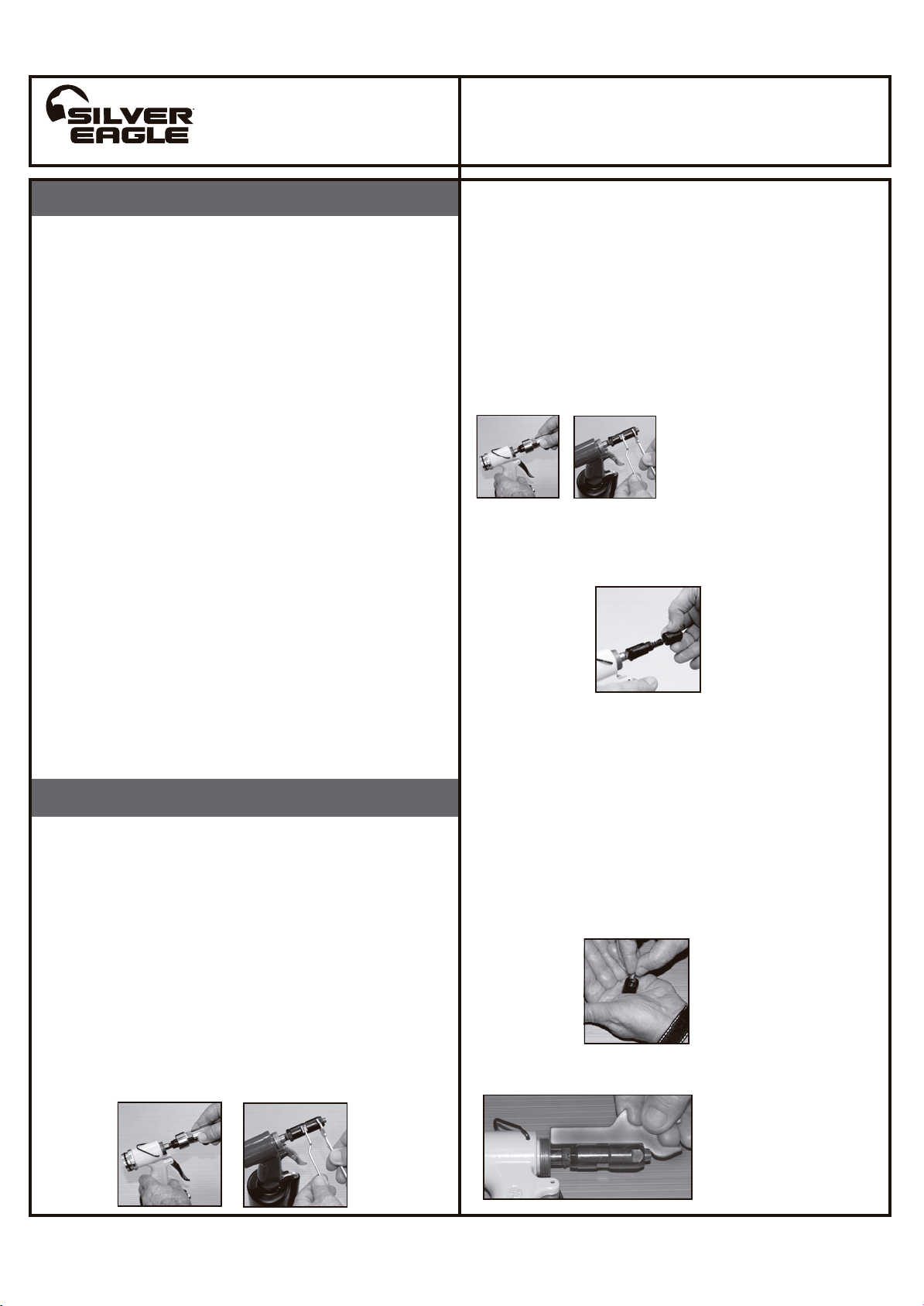
1. Retire el cilindro exterior (#PR14-02) como se muestra en la
Figura. 1 con las llaves incluidas.
2. Suelte la berola (#PR14-01) del cilindro exterior, enrosque la
berola deseada en el cilindro exterior por sólo 2 ó 3 giros. Favor
consultar la Figura 3.
3. A continuación, añadir unas gotas de grasa para herramientas
neumáticas de buena calidad en las mordazas y también añadir un
poco de grasa ligera al eje principal (#PR14-A09) del eje roscado
de la mordaza del cilindro.
4. Por último, atornille el cilindro exterior de nuevo en la remachadora
manualmente y apriete la berola y el cilindro exterior con las llaves
incluidas.
1. Retire el cilindro exterior (#PR14-02) como se muestra en la
Figura 1.
2. A continuación, utilizando las dos llaves incluidas suelte el portador de
la mordaza (#PR14-03) del cilindro de la mordaza (#PR14-
07) como se muestra en la Figura 2.
Desatornille manualmente en una superficie plana la mordaza del
cilindro que se acopla a la remachadora para permitir que el empujador
de la mordaza (#PR14-05) y el resorte del empujador de la mordaza
(#PR14-06) permanezcan acoplados a modo de montaje. Favor
consultar la Figura 3.
Tenga cuidado al desatornillar el portador de la mordaza ya que existe
una ligera presión del resorte que obliga al portador de la mordaza a
separarse del mango.
3. Al desenroscar el portador de la mordaza, incline la parte de la berola del
portador de la mordaza ligeramente hacia un ángulo inferior para
prevenir que se caigan las mordazas. Ver Figura 3.
4. Antes de volver a montarla, limpie a fondo con un cepillo y lubrique todas
las piezas del montaje internas con grasa para herramientas neumáticas
de buena calidad.
5. Montaje del juego de mordazas PR14-04. Sostenga el portador de
la mordaza en la palma de su mano tal como se muestra en la Figura 4
dejando aproximadamente 1/4" (6 mm) de espacio entre la palma y el
portador de la mordaza.
6. A continuación, introduzca cada mordaza en el portador de la mordaza
en un ángulo de 120 grados hasta que las tres mordazas estén
sobresalgan uniformemente a través del portador de la mordaza. Podrá
encontrar una pequeña cantidad de grasa blanca ligera entre cada
mordaza, así como entre las mordazas individuales en el portador de la
mordaza.
7. Mientras sujeta la remachadora hacia abajo en una superficie plana,
vuelva a ensamblar el portador de la mordaza en el cilindro de la
mordaza, e invierta el procedimiento para desmontarla.
Modelo:
SE1214
www.matcotools.com
1512186-23MA