Sime OPEN HYBRID MEM-ECO 25-6 Manual

Fonderie SIME S.p.A. 6328233B - 06/2022 - R0
INSTALLATION AND MAINTENANCE MANUAL
OPEN HYBRID MEM-ECO
EN
TRANSLATION OF THE ORIGINAL INSTRUCTIONS
To consult the documentation,
visit our website www.sime.it

2
SAFETY WARNINGS AND REGULATIONS
m
WARNINGS
–After having removed the packaging
make sure that the product supplied is
integral and complete in all its parts. If
this is not the case, please contact the
Dealer who sold the appliance.
–The appliance must be used
as intended by
Sime
who is not
responsible for any damage caused to
persons, animals or things, improper
installation, adjustment, maintenance
and improper use of the appliance.
–In the event of water leaks, disconnect
the appliance from the mains power
supply, close the water mains and
promptly inform professionally
qualified personnel.
–Periodically check that the operating
pressure of the water heating system
when cold is
1-1.2 bar
. If this is not the
case, increase the pressure or contact
professionally qualified personnel.
–If the appliance is not used for a long
period of time,
ONLY WHEN THERE IS
THE RISK OF FREEZING
, at least one
of the following operations must be
carried out:
-
set the main system switch to "OFF";
-
close the gas and water valves for the
water heating system.
–If there is the risk of freezing, leave
the gas valves open and ensure the
appliance is connected to the mains
power. This way the anti-freeze function
will remain active if set appropriately.
–In order to ensure optimal appliance
operations
Sime
recommends that
maintenance and checks are carried
out
ONCE A YEAR
.
–If the power cable is damaged, replace
it with a cable ordered as a spare part
with the same characteristics (type X).
Assembly must be by carried out by a
qualified professional.
m
WARNINGS
–
It is recommended that all operators
read this manual carefully in order to
use the appliance in a safe and rational
manner.
–
This manual
is an integral part of the
appliance. It must therefore be kept
for future reference and must always
accompany the appliance in the event
the appliance is transferred or sold to
another Owner or User or is installed
on another system.
–
Installation and maintenance
of this
appliance must be carried out by a
qualified company or by a professionally
qualified technician in accordance
with the instructions contained in the
manual. Once the work is complete,
the company or technician will issue a
declaration of conformity with national
and local technical standards and
legislation in force in the country where
the appliance will be used.
–
Any repairs on the appliance
must be
carried out solely by professionally
qualified personnel, using original
spare parts only. Failure to comply
with these instructions can jeopardise
the appliance’s safety and void the
warranty with immediate effect.
–
Fonderie SIME S.p.A.
reserves the
right to make improvements to
its products at any time without
prior notice, without compromising
their essential characteristics. The
graphic illustrations and/or images
in this document may show optional
accessories that vary according to the
country in which the appliance is used.

3
RESTRICTIONS
d
IT IS FORBIDDEN
–To allow children under the age of 8 to
use the appliance. The appliance can be
used by children no younger than 8 years
old, by people with physical or cognitive
disabilities, and by people lacking
experience or the necessary knowledge,
provided that they are supervised or
have been instructed on how to use
the appliance safely and that they
understand the risks associated with it.
–To allow children to play with the
appliance.
–To allow unsupervised children to
perform user maintenance and
cleaning.
–To use electrical devices or appliances
such as switches, electrical appliances etc
if you can smell fuel. If this should happen:
-
open the doors and windows to air the room;
-
close the gas isolation device;
-
promptly call for professional
assistance.
–To touch the appliance with bare feet or
with any wet part of the body.
–To carry out any technical intervention
or cleaning operation before having
disconnected the appliance from the
mains power by setting the main switch
to "OFF", and closing the gas supply.
d
IT IS FORBIDDEN
–To modify the safety or adjustment
devices without authorization and
instructions from the manufacturer.
–To block the condensate drain (if
present).
–To pull, detach or twist the electrical
cables coming out of the appliance
even if the appliance is disconnected
from the mains power supply.
–To block or reduce the size of the
ventilation openings of the room where
the appliance is installed, if present.
–Remove the mains power and gas
supply from the appliance if the
external temperature could fall below
ZERO (risk of freezing).
–To leave containers with flammable
substances in the room where the
appliance is installed.
–To dispose of the packaging material
irresponsibly as it could be dangerous.
Packaging must be disposed of as
specified by the legislation in force in the
country where the appliance will be used.
4
MANUAL STRUCTURE
This manual is organized as follows.
Dear Customer,
Thank you for purchasing a
Sime OPEN HYBRID MEM-ECO
boiler,
a new-generation modulating condensing device with technical
features and excellent performance, allowing you to satisfy your
heating and instant domestic hot water requirements with the
utmost safety and limited running costs.
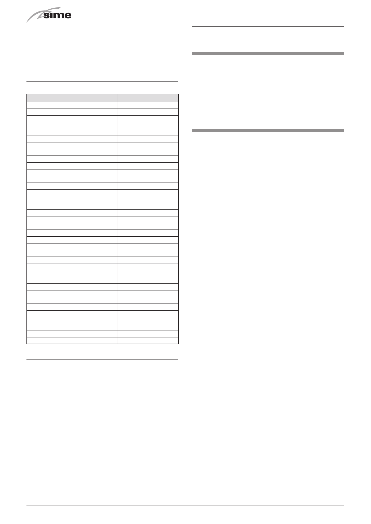
RANGE
MODEL CODE
OPEN HYBRID MEM-ECO 25-6 8117500
OPEN HYBRID MEM-ECO 25-6A 8118600
OPEN HYBRID MEM-ECO 25-8 8117501
OPEN HYBRID MEM-ECO 25-8A 8118601
OPEN HYBRID MEM-ECO 25-10 8117502
OPEN HYBRID MEM-ECO 25-12 8117503
OPEN HYBRID MEM ECO 30-6 8117504
OPEN HYBRID MEM ECO 30-6A 8118604
OPEN HYBRID MEM ECO 30-8 8117505
OPEN HYBRID MEM ECO 30-8A 8118605
OPEN HYBRID MEM ECO 30-10 8117506
OPEN HYBRID MEM ECO 30-12 8117507
OPEN HYBRID MEM ECO 35-6 8117508
OPEN HYBRID MEM ECO 35-6A 8118608
OPEN HYBRID MEM ECO 35-8 8117509
OPEN HYBRID MEM ECO 35-8A 8118609
OPEN HYBRID MEM ECO 35-10 8117510
OPEN HYBRID MEM ECO 35-12 8117511
OPEN HYBRID MEM-ECO 25-6 S 8117512
OPEN HYBRID MEM-ECO 25-6 S A 8118612
OPEN HYBRID MEM-ECO 25-8 S 8117513
OPEN HYBRID MEM-ECO 25-8 S A 8118613
OPEN HYBRID MEM-ECO 25-10 S 8117514
OPEN HYBRID MEM-ECO 25-12 S 8117515
OPEN HYBRID MEM ECO 30-6 S 8117516
OPEN HYBRID MEM ECO 30-6 S A 8118616
OPEN HYBRID MEM ECO 30-8 S 8117517
OPEN HYBRID MEM ECO 30-8 S A 8118617
OPEN HYBRID MEM ECO 30-10 S 8117518
OPEN HYBRID MEM ECO 30-12 S 8117519
OPEN HYBRID MEM ECO 35-6 S 8117520
OPEN HYBRID MEM ECO 35-6 S A 8118620
OPEN HYBRID MEM ECO 35-8 S 8117521
OPEN HYBRID MEM ECO 35-8 S A 8118621
OPEN HYBRID MEM ECO 35-10 S 8117522
OPEN HYBRID MEM ECO 35-12 S 8117523
COMPLIANCE
Our company declares that
OPEN HYBRID MEM-ECO
boilers
comply with the following directives:
–Gas Appliances EU Regulation 2016/426
–Low Voltage Directive 2014/35/EU
–Electromagnetic Compatibility Directive 2014/30/EU
–Ecodesign Directive 2009/125/EC
–Regulation (EU) No. 811/2013 - 813/2013
–Boiler Efficiency Directive 92/42/EEC
SYMBOLS
a
WARNING
To indicate actions which, if not carried out correctly,
can result in injury of a general nature or may damage
or cause the appliance to malfunction; these actions
therefore require particular caution and adequate
preparation.
f
ELECTRICAL HAZARD
To indicate actions which, if not carried out correctly,
could lead to injury of an electrical nature; these
actions therefore require particular caution and
adequate preparation.
d
IT IS FORBIDDEN
To indicate actions which MUST NOT BE carried out.
m
CAUTION
To indicate particularly important and useful
information.
OPEN HYBRID MEMECO SYSTEM
INDICE 5
1 SYSTEM description .................... 6
2 Installation........................... 19
3 Commissioning ....................... 32
4 Maintenance ......................... 48
5 Application diagrams .................. 51
6 Annexes ............................. 59
DESCRIPTION OF THE BOILER
TABLE OF CONTENTS 65
1 Description of the appliance ............ 66
2 Installation........................... 73
3 Commissioning ....................... 81
4 Maintenance ......................... 87
5 Annexes ............................. 90

5
OPEN HYBRID MEMECO SYSTEM
INDICE
1SYSTEM DESCRIPTION 6
1.1 Operation ......................................7
1.1.1 Domestic hot water . . . . . . . . . . . . . . . . . . . . 7
1.1.2 Heating .............................. 7
1.1.3 Cooling .............................. 8
1.1.4 Anti-freeze function .................... 8
1.1.5 Anti-blocking function .................. 8
1.1.6 Photovoltaic function ................... 8
1.1.7 Automatic filling function ............... 8
1.1.8 Automatic degassing function ........... 8
1.2 Structure ......................................9
1.3 Technical features ..............................10
1.3.1 Boiler ............................... 10
1.3.2 Heat pump........................... 11
1.4 Main water circuits .............................13
1.4.1 Open Hybrid MEM-ECO base ............ 13
1.4.2 Open Hybrid MEM-ECO base - High
Temperature kit....................... 13
1.4.3 Open Hybrid MEM-ECO base - High
Temperature Kit - Solar Kit ............. 14
1.5 Sensors.......................................15
1.6 Expansion vessels ..............................15
1.7 Circulation pump ..............................15
1.7.1 High temperature system pump ......... 15
1.7.2 Low temperature system pump.......... 15
1.7.3 Controlling operation of the pump ....... 15
1.8 Mem Remote Control ...........................16
1.9 Electrical panel ................................16
1.10 Wiring diagram ................................17
2INSTALLATION 19
2.1 Receiving the product ...........................19
2.2 Dimensions ...................................19
2.3 Handling ......................................19
2.4 Installation of the Open Hybrid MEM-ECO System....19
2.4.1 Heat pump installation................. 23
2.5 Smoke outlet and combustion air inlet .............24
2.5.1 Openings in the frame to allow the passage
of the smoke outlet.................... 24
2.5.2 Separate ducts (Ø 60/100mm) ........... 25
2.5.3 Separate ducts (Ø 60mm and Ø 80mm) ... 25
2.6 Mem Remote Control Installation .................26
2.7 Solar thermal storage tank connections............26
2.8 Position of the sensors . . . . . . . . . . . . . . . . . . . . . . . . . . 27
2.9 Electrical connections...........................28
2.9.1 Connection to the mains ............... 28
2.9.2 Component connections................ 28
2.9.3 Boiler connections .................... 28
2.10 Filling operations...............................29
2.10.1 Automatic degassing function ........... 30
2.10.2 Setting boiler parameters .............. 30
2.11 Emptying operations ............................31
3COMMISSIONING 32
3.1 Preliminary operations ..........................32
3.2 Commissioning ................................32
3.3 Parameter setting and display ....................33
3.4 Complete list of parameters......................34
3.5 Parameter functions ............................37
3.5.1 General settings ...................... 37
3.5.2 Generation System Settings............. 38
3.5.3 Input and Output Configuration .......... 40
3.5.4 Heating ............................. 41
3.5.5 Cooling.............................. 43
3.5.6 DHW................................ 44
3.5.7 Energy Settings....................... 45
3.5.8 Communication....................... 46
3.6 Setting the circulation pump .....................47
3.6.1 Settings mode ........................ 47
3.6.2 Venting.............................. 47
3.6.3 Manual restart ....................... 47
3.6.4 Locking/unlocking the button ........... 47
3.6.5 Activating factory settings .............. 47
3.6.6 Manual restart ....................... 47
4MAINTENANCE 48
4.1 Adjustments...................................48
4.2 Alarms .......................................48
4.3 Pump troubleshooting...........................50
4.4 Pump troubleshooting...........................50
4.5 Alarm log .....................................50
5APPLICATION DIAGRAMS 51
6ANNEXES 59
6.1 Boiler product board ............................59
6
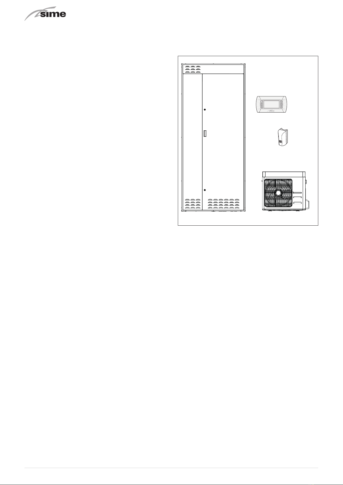
1 SYSTEM DESCRIPTION
OPEN HYBRID MEM-ECO
systems are built-in, “modular” sys-
tems for heating and cooling rooms and for the production of
domestic hot water. They can be "assembled" on the basis of
the system needs requested by the customer.
The basic
OPEN HYBRID MEM-ECO
structure consists of:
– Enclosure frame, fully recessed for outdoors, or in cabinet
for indoors. This must be ordered and installed before the
"components" are requested.
– Basic appliances/components (to be installed inside the
built-in housing structure):
– Hot water storage tank in stainless steel with a capacity
of 150 litres.
– 25, 30 or 35 kW hot water on-demand condensing boiler
– Main electrical panel.
– 8 litre hot water expansion vessel
– Relief valve and pump.
– Pipes for connecting all the appliances which make up
the system.
– A bag containing nuts, bolts and screws, the technical
data plate and the assembly instructions.
– Single column solar panel assembly complete with all the
water circuit elements needed for operating a solar ther-
mal circuit if installed (optional).
– Thermostatic mixer (optional)
– 12 litre solar thermal expansion vessel (optional)
Additional appliances/devices to complete the basic/mini-
mum structure:
–
Sime
SHP M ECO
heat pump to be selected on the basis of
system requirements
– MRM Remote Control to manage the entire system.
In the basic configuration,
OPEN HYBRID MEM-ECO
systems
provide hot water at a maximum delivery temperature of 60°C
and return temperature of 50°C, but they can also be integrat-
ed with the following optional kits:
– High temperature kit: to manage system terminals such as
radiators, fan convectors.
– Solar kit: to use the SIMESOL 182 solar panel to produce
domestic hot water maximising the use of alternative ener-
gy and limiting boiler usage.
m
WARNING
– With this appliance the USE OF THE EXTERNAL
SENSOR IS COMPULSORY for the boiler to work
with a sliding temperature (delivery temperature
varies automatically on the basis of the external
temperature detected), for the activation of the an-
ti-freeze function and to calculate the convenience
of the energy sources.
– Commissioning of the
Open Hybrid MEM-ECO
system
must be carried out by qualified technicians.
Fig. 1

7
1.1 Operation
1.1.1 Domestic hot water
The 150 litre hot water storage tank in STAINLESS STEEL is
made exclusively from renewable sources with the following
priorities:
1
Solar Thermal Energy (if present);
2
Heat pump.
The domestic hot water prepared in the storage tank always
remains in the boiler before being used. The boiler burner is
activated by the MEM only if the inlet temperature does not
reach the setpoint set by the user.
– Weekly programming from the MEM display for the prepa-
ration of the domestic hot water and therefore of the stor-
age tank.
– The solar thermal system (if present) can prepare the 150
litres of hot water in the storage tank at the maximum tem-
perature of 90°C. The actual energy ratio depends on the
solar rays which the solar collector is subject to. The solar
thermal pump is managed by the MEM on the basis of the
storage tank-collector and implements the ANTI-FREEZE
COLLECTOR, COOLING COLLECTOR).
– The heat pump can prepare 150 litres of hot water in the
storage tank up to the maximum temperature of 50°C.
Preparation by the heat pump only occurs in periods in
COMFORT mode. To allow for preparation when also in RE-
DUCED mode, act on the specific parameter.
– The amply dimensioned plate heat exchanger allows the
heat pump to operate with high COP values also for the
preparation of domestic hot water in addition to reduced
restore times. Management by the MEM includes activation
of the heat pump only when the storage tank is almost com-
pletely depleted of hot water in order to reduce the number
of start-ups to a minimum and to allow the heat pump to
operate at low temperatures (high COP).
– The actual preparation temperature of the storage tank by
the heat pump is calculated dynamically by the MEM on the
basis of the efficiency conditions (external temperature +
delivery temperature).
– The MEM manages the heat pump domestic hot water pri-
ority on the basis of some modifiable parameters:
–Priority in the summer (COOLING or DOMESTIC HOT WATER
with maximum time to be set). Default priority COOLING
– Priority in the winter (HEATING or DOMESTIC HOT WATER
with maximum time to be set). Default priority DOMESTIC
HOT WATER for no more than 30 minutes.
– The ANTI-LEGIONELLA function, if enabled, includes prepa-
ration of the storage tank at a temperature of 55°C (main-
tained for approximately 2 hours) once a week for bacteria
sanitisation.
1.1.2 Heating
– The heating request is made by means of the dry contact
(for example, a safety limit microswitch, etc..).
– The medium-low temperature heating circuit can reach a
maximum delivery temperature of 55°C with only the heat
pump operating. It is possible to reach a temperature of
60°C (return 50°C) with the combined heat pump - boiler
operation.
– The 30 litre inertial storage tank acts as a thermal flywheel
(needed by the heat pump) and hydraulic separator allow-
ing operation with any flow rate processed by the system.
Thanks to the specific design, the inertial tank always guar-
antees the best possible working conditions for the heat
pump making it work at the minimum temperature made
available by the system (no mixing of the return water inside
the inertial storage tank).
– The delivery setpoint can be set by the user at a fixed value
or it can be calculated dynamically by the MEM on the basis
of the external temperature and the selected climatic curve.
– System safety thermostat (50°C fixed calibration with the
option of deactivating the parameter) to protect the radiat-
ing system at low temperatures.
– In every operating condition, the MEM control unit calcu-
lates the heat pump COP (external temperature + delivery
temperature) and therefore whether the boiler or the heat
pump is most appropriate and it controls the subsequent
activation. If the most appropriate source is not sufficient to
cover the system needs, the other source can be activated
at the same time for the minimum energy needed to reach
the setpoint (this function can be set by the specific param-
eters). This way AND (simultaneous) operation is possible of
the sources allowing the heat pump to be activated even in
conditions in which it would normally be switched off as the
power output is less than the system requirements.
– The power modulation of the heat pump and the boiler is
always controlled by the MEM at the minimum level neces-
sary to meet the set system setpoint (there is no increase in
the generator setpoint in relation to the system if not nec-
essary).
–The defrost function of the heat pump is controlled by the MEM
eliminating almost all temporary comfort loss and compen-
sating the energy withdrawn from the system or the boiler.
– Using the MEM parameters, it is possible to set gas and
electrical energy costs to allow the dynamic calculation of
the financial advantage of using each individual source. If
this data is not available, the energy convenience will still
be calculated (primary energy equivalence).
– The high efficiency and high flow-head modulating pump
is able to guarantee the necessary flow rate to the system
adjusting the number of revolutions (and therefore the con-
sumption) on the basis of the instantaneous absorbed pow-
er of the system.
– Option of installing a HIGH TEMPERATURE KIT for an addi-
tional heating circuit with delivery temperature up to 80°C.
This circuit is used exclusively by the boiler as the temper-
atures are too high for the heat pump to operate. If the re-
quest is made for the boiler to operate together with the
high and low temperature circuits, the boiler generates with
a high temperature setpoint while the low-temperature cir-
cuit is adjusted by means of a distribution valve before mix-
ing inside the puffer to obtain the set temperature.

8
1.1.3 Cooling
– Setting the summer mode (cooling) from the remote display
or remote contact (option of installing a summer/winter se-
lector for the user's convenience - not supplied).
– The cooling request is made by means of the dry contact (for
example, a safety limit microswitch, etc..).
– Heat pump operation only in cool mode.
– Fixed system setpoint set by the user.
– Humidistat input (dry contact) for a second setpoint which
can be set by the installer for dehumidification (reduction)
or to prevent the formation of condensate in the radiating
system (increase).
– The power modulation of the heat pump is always controlled
by the MEM at the minimum level necessary to meet the set
system setpoint (there is no reduction in the heat pump set-
point in relation to the system if not necessary).
– 30 litre puffer and pipes with insulation present. The install-
er must complete the insulation of the connection points as
indicated in the installation manual.
1.1.4 Anti-freeze function
–Protection activated by the MEM with activation of the pumps,
valves and generators on the basis of the temperatures de-
tected by the sensors (electrical power is required). It is es-
sential that there is a correctly installed external sensor.
1.1.5 Anti-blocking function
– Function controlled by the MEM with the activation of all the
active organs after a period of inactivity to prevent blocking
(electrical power is required).
1.1.6 Photovoltaic function
– Function managed by the MEM to increase the amount of
auto-consumption of the electrical energy produced by a
photovoltaic system if installed.
1.1.7 Automatic filling function
– If system pressure drops with the subsequent intervention
of the low pressure alarm, it is possible to refill simply be
pressing a button on the display.
1.1.8 Automatic degassing function
– Function to be activated by the installer or technical per-
sonnel to allow rapid degassing of the air inside the system
during commissioning
– In any case, the system must be made according to the di-
agrams present in the installation manual and goose-neck
fittings are to be avoided.
– If they cannot be avoided, the installer must ensure that
there are bleed devices in the top sections.
9
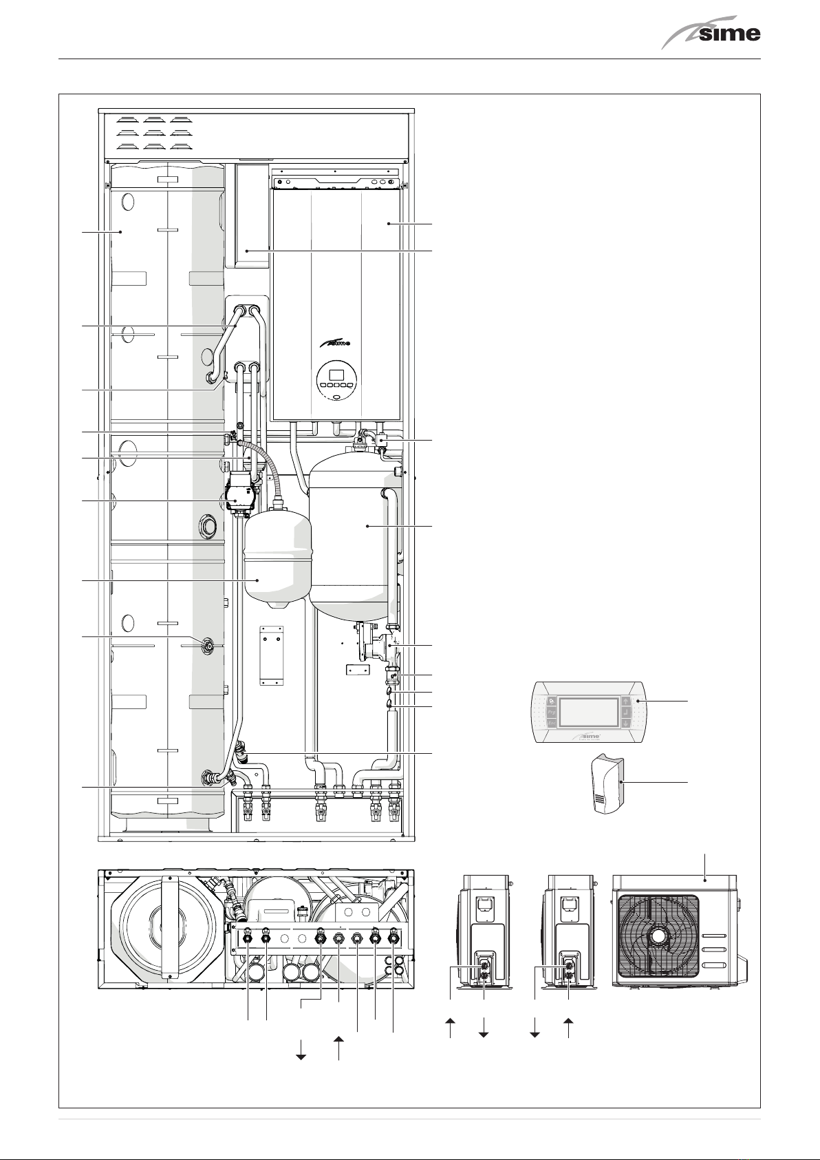
1.2 Structure
1
2
6
5
4
3
8
7
9
18
15
20
19
16
14
13
12
11
10
17
E U IN
PdC
OUT
PdC
Rbt
Mbt
G
OUT
SHP M ECO
006-008 SHP M ECO
010-012
IN
21
INOUT
Fig. 2
KEY
1
150 litre domestic hot water storage tank
2
Plate heat exchanger (
Sp
)
3
Sensor socket
B1
4
Sensor
B5
5
Diverter valve (
VD
)
6
Domestic hot water pump (
PS
)
7
Domestic hot water expansion vessel (
Ve
)
8
Sensor socket
B2
9
Domestic hot water storage tank drain valve (
Rs
)
10
Domestic hot water relief valve (
Vs
)
11
Sensor
B3
12
System safety thermostat (
TS
)
13
Check valve (
Vr
)
14
Low temperature system pump
(
PI
)
15
Inertial puffer
16
Automatic filling
(EV)
17
Electrical panel
18
Condensation boiler
19
Mem Remote control
20
External sensor (
SE
)
21 Sime
SHP M ECO heat pump
E
Domestic hot water inlet (Ø 1/2”)
U
Domestic hot water output (Ø 1/2”)
IN PdC
Heat pump return (Ø 3/4”)
OUT PdC
Heat pump delivery (Ø 3/4”)
Rbt
Low temperature system return (Ø 3/4”)
Mbt
Low temperature system delivery (Ø 3/4”)
G
Gas supply (Ø 3/4”)
IN
Heat pump inlet (Ø 1”)
OUT
Heat pump outlet (Ø 1”)

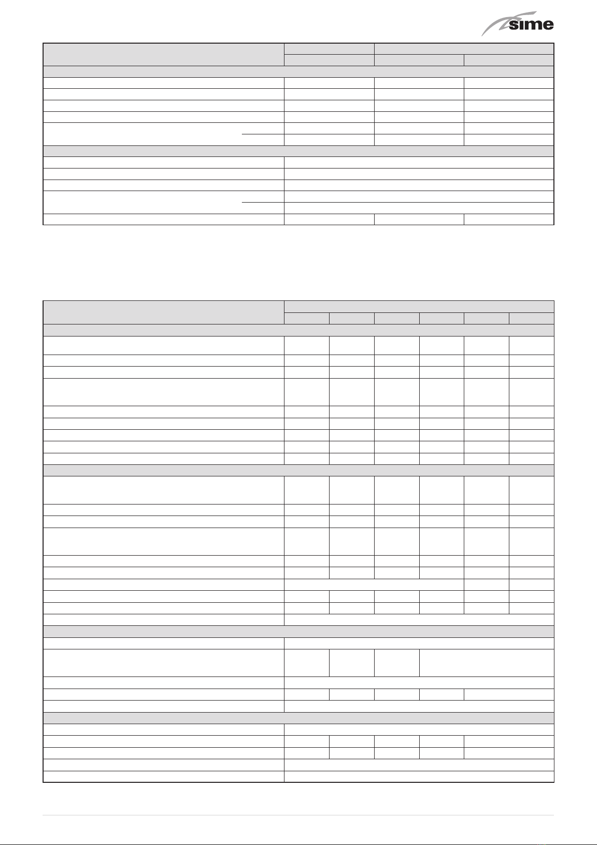
10
1.3 Technical features
1.3.1 Boiler
DESCRIPTION
OPEN HYBRID MEM-ECO OPEN HYBRID MEM ECO
25 30 35
CERTIFICATIONS
Country of intended installation IT – ES – PT – SI – PL
Fuel G20 / G31
PIN number II2HM3P - II2H3P
Category II2HM3P
Appliance classification B23P - B33P - B53P - C13 - C33 - C43 - C53 - C63 - C83 - C93 -
C(10)3
Class NOx (*) 6 (< 56 mg/kWh)
DHW rated useful heat output kW 24,0 28,0 34,8
HEATING PERFORMANCE
HEAT INPUT (**)
Nominal flow (Qn max) kW 24 24 30
Minimum flow (Qnw min) kW 4,8 4,8 6
HEAT OUTPUT
Nominal (80-60°C) (Pn max) kW 23,6 23,6 29,5
Nominal (50-30°C) (Pn max) kW 25,7 25,7 32,2
Minimum G20 (80-60°C) (Pn min) kW 4,7 4,7 5,9
Minimum G20 (50-30°C) (Pn min) kW 5,1 5,1 6,5
Minimum G31 (80-60°C) (Pn min) kW 4,7 4,7 5,9
Minimum G31 (50-30°C) (Pn min) kW 5,1 5,1 6,5
EFFICIENCY
Max useful efficiency (80-60°C) % 98,3 98,3 98,3
Min useful efficiency (80-60°C) % 97,9 97,9 98,3
Max useful efficiency (50-30°C) % 107,1 107,1 107,3
Min useful efficiency (50-30°C) % 106,3 106,3 108,3
Useful efficiency at 30% of load (40-30°C) % 108,5 108,5 108,5
Losses after shutdown at 50°C W 88 88 88
DOMESTIC HOT WATER PERFORMANCE
Nominal heat input (Qnw max) kW 24 28 34,8
Minimum heat input (Qnw min) kW 4,8 6
Specific D.H.W. flow rate ∆T 30°C (EN 13203) l/min 11,2 12,9 16,5
Continuous D.H.W. flow rate (∆T 25°C / ∆T 35°C) l/min 13,6 / 9,7 16,1 / 11,5 20 / 14,3
Minimum D.H.W. flow rate l/min 2 2 2
Max (PMW) / Min Pressure bar 7 / 0,5 7 / 0,5 7 / 0,5
kPa 700 / 50 700 / 50 700 / 50
ENERGY PERFORMANCE
HEATING
Heating seasonal energy efficiency class AAA
Heating seasonal energy efficiency % 93 93 93
Sound power dB(A) 53 53 50
DOMESTIC HOT WATER
Domestic hot water energy efficiency class AAA
Domestic hot water energy efficiency % 86 84 85
Stated domestic hot water profile load XL XL XL
ELECTRICAL SPECIFICATIONS
Power supply voltage V 230
Frequency Hz 50
Absorbed electrical power (Qn max) W 85 85 92
Absorbed electrical power at (Qn min) W 52 52 57
Absorbed electrical power in stand-by W 3,6 3,6 3,6
Electrical protection degree IP X5D
COMBUSTION DATA
Smoke temperature at Max/Min flow (80-60°C) °C 82 / 71 89 / 71 77 / 67
Smoke temperature at Max/Min flow (50-30°C) °C 59 / 51 71 / 51 58 / 49
Smoke flow Max/Min g/s 11,2 / 2,2 13,1 / 2,2 16,3 / 2,8
CO2 at Max/Min flow rate (G20) % 9,0 / 9,0 9,0 / 9,0 9,0 / 9,0
CO2 at Max/Min flow rate (G31) % 10,0 /10,0 10,0 /10,0 10,0 / 10,0
NOx measured mg/kWh 37 37 33
11
DESCRIPTION
OPEN HYBRID MEM-ECO OPEN HYBRID MEM ECO
25 30 35
NOZZLES GAS
Number of nozzles No. 1 1 1
Nozzle diameter (G20-G31) mm 5,3 5,3 6,5
Gas consumption at Max/Min flow rate (G20) m3/h 2,54 / 0,5 2,96 / 0,50 3,70 / 0,63
Gas consumption at Max/Min flow rate (G31) kg/h 1,87 / 0,37 2,17 / 0,37 2,71 / 0,46
Gas supply pressure (G20/G31) mbar 20 / 37 20 / 37 20 / 37
kPa 2 / 3,7 2 / 3,7 2 / 3,7
TEMPERATURE PRESSURE
Max operating temperature (T max) °C 85
Heating adjustment range °C 20÷80
Domestic hot water adjustment range °C 10÷60
Max operating pressure (PMS) bar 3
kPa 300
Water content in boiler l 4,75 4,75 4,95
(*) NOx class according to UNI EN 15502-1:2015
(**) Heat input calculated using the lower heat output (Hi)
Lower Heat Output (Hi)
G20 Hi.
9.45 kW/m
3
(15°C, 1013 mbar) -
G31 Hi.
12.87 kW/kg (15°C, 1013 mbar)
1.3.2 Heat pump
DESCRIPTION
SHP M ECO
06 06A 08 08A 10 12
COOLING
Cooling capacity (1) kW 3,20 / 5,02
/ 5,52 (*)
3,22 / 5,19
/ 5,71 (*)
3,80 / 6,08
/ 6,69 (*)
3,74 / 6,14
/ 6,65 (*)
4,66 / 7,53
/ 8,28 (*)
4,55 / 8,51
/ 9,36 (*)
Absorbed power (1) kW 1,60 1,64 1,99 1,97 2,39 2,79
E.E.R. (1) W/W 3,14 3,16 3,05 3,12 3,15 3,05
Cooling capacity (2) min/nom/max kW 4,82 / 6,18
/ 6,80 (*)
5,52 / 6,37
/ 6,72 (*)
4,91 / 7,72
/ 8,49 (*)
5,58 / 8,03
/ 8,67 (*)
6,22 / 9,50
/ 10,45 (*)
6,41 /
11,60 /
12,76 (*)
Absorbed power (2) kW 1,28 1,30 1,76 1,79 2,15 2,79
E.E.R. (2) W/W 4,82 4,90 4,38 4,49 4,41 4,16
SEER (5) W/W 4,12 4,42 4,25 4,51 4,15 4,25
Water flow rate (1) L/s 0,24 0,25 0,28 0,29 0,36 0,41
User-side heat exchanger head loss (1) kPa 2,0 3,2 2,8 5,3 6,9 8,8
HEATING
Heat Output (3) min/nom/max kW 3,95 / 6,08
/ 6,99 (*)
4,47 / 6,13
/ 7,48 (*)
3,95 / 7,81
/ 8,98 (*)
4,51 / 7,81
/ 9,42 (*)
5,33 /
10,10 /
11,62 (*)
5,33 /
11,80 /
13,57 (*)
Absorbed power (3) kW 1,35 1,25 1,78 1,71 2,28 2,73
C.O.P. (3) W/W 4,51 4,90 4,38 4,57 4,43 4,32
Heat Output (4) min/nom/max kW 3,82 / 5,88
/ 6,76 (*)
4,29 / 5,97
/ 7,03 (*)
3,80 / 7,58
/ 8,72 (*)
4,24 / 7,71
/ 8,99 (*)
5,18 / 9,76
/ 11,22 (*)
5,13 /
11,47 /
13,19 (*)
Absorbed power (4) kW 1,66 1,58 2,17 2,11 2,80 3,33
C.O.P. (4) W/W 3,54 3,78 3,50 3,65 3,48 3,44
SCOP (6) W/W 4,46 4,53 4,47
Water flow rate (4) L/s 0,28 0,29 0,37 0,37 0,47 0,55
User-side heat exchanger head loss (4) kPa 2,1 4,4 3,3 8,6 9,7 13,1
Water energy efficiency 35°C / 55°C Class A+++ / A++
COMPRESSOR
Type Twin Rotary DC Inverter
Refrigerating oil (type)
ESTEL
OIL RB
74A F
ESTEL
OIL VG74
ESTEL
OIL RB
74A F
ESTEL OIL VG74
Number of compressors 1
Oil charge (quantity) L 0,67 0,62 0,67 0,62 1
Cooling circuits 1
REFRIGERANT
Type R32
Refrigerant charge (7) kg 1,5 0,97 1,5 0,97 2,5
Quantity of refrigerant in tons of Co2 equivalent (7) ton 1,0 0,7 1,0 0,7 1,7
Design pressure (high/low) in heat pump mode bar 42,8 / 1,3
Design pressure (high/low) in chiller mode bar 42,8 / 3,5
(*) Activating the maximum Hz function.

12
DESCRIPTION
SHP M ECO
06 06A 08 08A 10 12
EXTERNAL ZONE FANS
Type DC Brushless Motor
Number 1
INTERNAL HEAT EXCHANGER
Type of internal heat exchanger Plate
No. of internal heat exchangers 1
Water content L 0,9 0,6 0,9 0,6 1,2
WATER CIRCUIT
Nominal useful head (1) kPa 78,8 74,9 76,0 71,0 68,9 63,4
Water content of the hydronic circuit L 1,4 1,14 1,4 1,14 1,8
Maximum pressure on water side bar 6
Plumbing connections inch 1” M
Minimum water volume L 40 50 60
Circulator pump maximum power kW 0,075 0,10 0,075 0,10 0,075
Circulator pump maximum current draw A 0,38 0,66 0,38 0,66 0,38
Energy Efficiency Index (EEI) circulator pump ≤ 0,21
NOISE LEVEL
Sound power Lw (8) dB(A) 64 65
Sound power at 1 m distance Lp1 (9) dB(A) 49,8 49,4 50,4
Sound power at 10 m distance Lp10 (9) dB(A) 32,8 32,7 33,7
ELECTRICAL SPECIFICATIONS
Power supply 230V/1/50Hz
Maximum absorbed power kW 3,5 3,4 3,9 4,1 4,6 5,1
Maximum absorbed current A 15,1 15,5 17,0 18,7 20,2 22,1
Maximum power absorption with anti-freeze kit kW 3,6 3,5 4,0 4,2 4,8 5,2
Maximum current absorption with anti-freeze kit A 15,6 15,9 17,6 19,1 20,7 22,7
Power supply unit 230V/1PH+PE/50Hz
On-board control circuit 12V/1/50Hz
Remote control circuit 12V/1/50Hz
Fan power supply 230V/1/50Hz
DIMENSION AND WEIGHTS
Dimensions (WxHxD) mm 924 x 828 x 377 1047 x 936 x 455
Max dimensions of package (WxHxD) mm 970 x 985 x 395 1080 x 1130 x 510
Shipping weight kg 84 110
Operating weight kg 72 96
Performance with the following conditions:
(1) COOLING: external air temperature 35°C; water temperature in/out 12/7°C..
(2) COOLING: external air temperature 35°C; water temperature in/out 23/18°C..
(3) Heating: external air temperature 7°C b.s. 6°C b.u.; water temperature in/out 30/35°C..
(4) Heating: external air temperature 7°C b.s. 6°C b.u.; water temperature in/out 40/45°C..
(5) COOLING: Input/output water temperature 7/12°C.
(6) Heating: average climatic conditions; Tbiv=-7°C; water temperature in/out 30/35°C.
(7) Indicative data subject to change. For the correct data, always refer to the technical label affixed to the unit.
(8) Sound power: condition heating mode (3); value determined based on measurements carried out in accordance with standard
UNI EN ISO 9614-2, in full compliance with the requirements of Eurovent certification.
(9) Sound pressure: value calculated from the sound power level using the ISO 3744:2010 standard.

13
1.4 Main water circuits
1.4.1 Open Hybrid MEM-ECO base
LOW
TEMPERATURE
SYSTEM
PUFFER
PI
Vr
Vr PS
Vs
Sp
Water mains
Water mains
DOMESTIC HOT WATER
STORAGE HEATER
VD
F
HEAT
PUMP
MU E R
SE
Vr
B2
B5
B3
TS
B1
Ve
VM
Fig. 3
1.4.2 Open Hybrid MEM-ECO base - High Temperature kit
1
LOW
TEMPERATURE
SYSTEM
PI
PS
Water mains
Water mains
Radiator
VD
F
HEAT
PUMP
MU E R
SE
B2
B5
B3
TS
B1
Ve
VM
VAT
PUFFER
DOMESTIC HOT WATER
STORAGE HEATER
Vr
Vr
Vs
Sp
Vr
Fig. 4

14
1.4.3 Open Hybrid MEM-ECO base - High Temperature Kit - Solar Kit
3
2
1
LOW
TEMPERATURE
SYSTEM
PI
Vr
Vr PS
Vs
Sp
Water
Mains
Water mains
Solar
unit
VeS Radiator
VD
F
HEAT
PUMP
SOLAR
COLLECTOR
MU E R
SE
Vr
B2
B5
B4
B3
TS
B1
Ve
VM
VAT
PUFFER
DOMESTIC HOT WATER
STORAGE HEATER
Fig. 5
KEY
Vr
Check valve
VD
Diverter valve
Vs
Relief valve
TS
Safety thermostat (low temperature system)
PS
Domestic hot water pump
PI
System pump (low temperature)
Sp
Plate heat exchanger
Ve
Domestic hot water expansion vessel
VeS
Solar expansion vessel (optional)
VM
Domestic hot water valve (optional)
VAT
High temperature valve (optional)
B1
Domestic Hot Water High Sensor
B2
Domestic Hot Water Low Sensor
B3
Low Temperature system delivery sensor
B4
Solar Collector Sensor (supplied with the Solar Kit)
B5
DHW Inlet O-ring sensor (in boiler)
SE
External sensor
F
Y Filter (not supplied, the responsibility of the installer)
M
Delivery
R
Return
U
DHW Output
E
DHW Inlet
1
HIGH TEMPERATURE KIT
2
SOLAR KIT
3
SOLAR PANEL
15
1.5 Sensors
The sensors installed have the following characteristics:
– B1 - Domestic Hot Water Storage Tank High Sensor NTC
R25°C; 10kΩ
– B2 - Domestic Hot Water Storage Tank Low Sensor NTC
R25°C; 10kΩ
– B3 - Low Temperature system delivery sensor NTC R25°C;
10kΩ
– B4 - Solar Collector Sensor (supplied with the Solar Kit)
PT1000
– B5 -DHW Inlet O-ring sensor (in boiler) NTC R25°C; 10kΩ
– SE - External sensor NTC R25°C; 10kΩ
Correspondence of Temperature Detected/Resistance
Examples of reading:
TR=75°C → R=1925Ω
TR=80°C → R=1669Ω
TR
0°C 1°C 2°C 3°C 4°C 5°C 6°C 7°C 8°C 9°C
Resistenza R (Ω)
0°C
27279
17959
12090
8313
5828
4161
3021
2229
1669
1266
973
26135
17245
11634
8016
5630
4026
2928
2164
1622
1232
25044
16563
11199
7731
5440
3897
2839
2101
1577
1199
24004
15912
10781
7458
5258
3773
2753
2040
1534
1168
23014
15289
10382
7196
5082
3653
2669
1982
1491
1137
22069
14694
9999
6944
4913
3538
2589
1925
1451
1108
21168
14126
9633
6702
4751
3426
2512
1870
1411
1079
20309
13582
9281
6470
4595
3319
2437
1817
1373
1051
19489
13062
8945
6247
4444
3216
2365
1766
1336
1024
18706
12565
8622
6033
4300
3116
2296
1717
1300
998
10°C
20°C
30°C
40°C
50°C
60°C
70°C
80°C
90°C
100°C
1.6 Expansion vessels
The expansion vessel installed on the boilers has the following
characteristics:
Expansion vessel
Capacity (l) Prefilling
(kPa) (bar)
in boiler
9 100 1
domestic hot water
8 300 3
solar
12 250 2.5
(*) Conditions of:
Average operating temperature 70°C (with high tempera-
ture system 80/60°C)
Start temperature at system filling 10°C.
m
WARNING
– The difference in height between the relief valve
and the highest point of the system cannot exceed
6 metres. If the difference is greater than 6 metres,
increase the prefilling pressure of the expansion
vessel and the system when cold by 0.1 bar for each
meter increase.
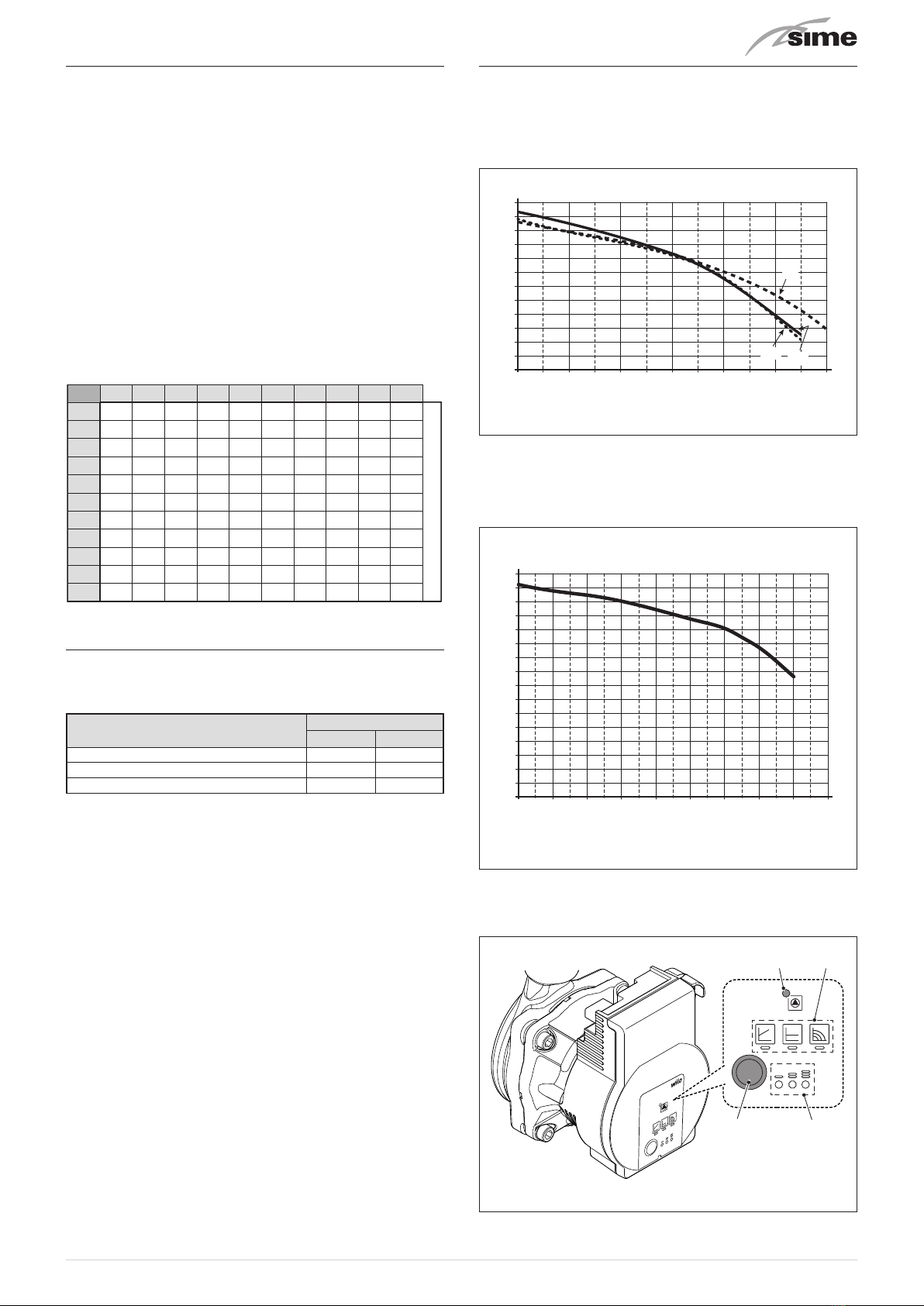
1.7 Circulation pump
The flow-head performance curve for the pumps used in the
Open
Hybrid MEM-ECO
Systems are indicated in the following graphs:
1.7.1 High temperature system pump
RESIDUAL HEAD (mbar)
0
0 800 1000 1200600400200
100
200
300
400
500
600
30
25
35
FLOW (l/h)
Fig. 5
1.7.2 Low temperature system pump
Flow-head-Performance Diagram (Pump at max speed and
∆p constant).
00 800 1000 1200 1400 1600
1800
600400200
100
200
300
400
500
RESIDUAL HEAD (mbar)
FLOW (l/h)
600
700
800
Fig. 6
1.7.3 Controlling operation of the pump
1 2
34
Fig. 7
16
1
Operating LED: during normal operation, the LED lights
up green. In the event of a fault, it emits warning signals
as detailed below.
LED colour Status Troubleshooting
LED off No electrical power
Red/Green Flashing Anomaly in progress
Red Flashing Anomaly in progress
Red On Permanent safety shutdown
For “Pump troubleshooting” see the relevant section at the
end of the manual.
2
Selected settings mode: ∆p-v, ∆p-c and constant speed
3
Selected characteristic curve: I, II, III for the specific set-
tings mode
4
Command button to set the pump for exclusive use by the
installer or an authorised technician (for further informa-
tion, please see “Setting the circulation pump”.
1.8 Mem Remote Control
The MEM Remote Control manages the entire system
OPEN HYBRID MEM-ECO.
Prg
Esc
156
Backlit display
82
31
Button Function
Alarm display (if present)
Red flashing light = alarm present
Access to parameters menu
(press and hold)
Return to previous menu or the Main screen
Scroll forwards
Confirm the selection of an item in the menu
or modification of value/data
Scroll backwards
Fig. 8
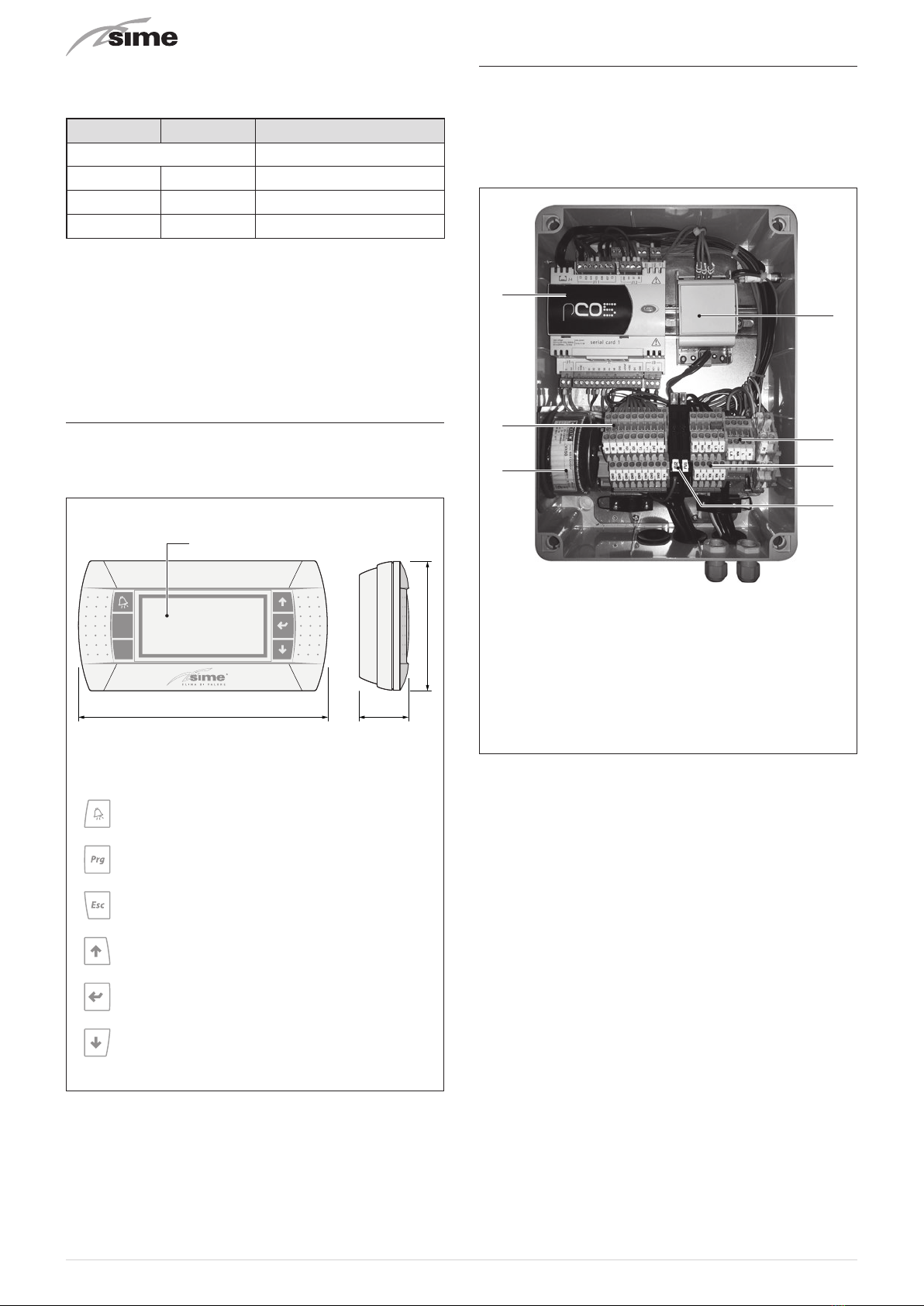
1.9 Electrical panel
To facilitate the electrical connections,it is recommended that
the panel is hooked to a clip on the domestic hot water stor-
age tank. The panel is equipped with the following pre-cabled
components which require connection.
1
3
6
2
4
5
7
KEY
5
Control unit
6
Communication bus converter
7
Transformer
8
Power supply terminals
9
Low voltage terminals
10
High voltage terminals
11
Fuses
Fig. 9

17
1.10 Wiring diagram
Y2
Y1
B -
A +
GNX
MOD-BUS
CONVERTOR
230V - 24V
TRANSFORMER
30VA
SP1
230V
0
230
GND
A
B
24
0
F2
T 2A
CABLE
SUPPLIED 6m
Extendable up to 50m
(RJ12 telephone cable)
24V
B4
B1
B2
B3
B5
B6
B8
ID1
GND
ID2
PE
L
N
N06
N07
N01
NA
LA
TS
MO3
MO1
12 3
LV system protection
(present in electrical panel)
CONTROL UNIT
EARTH
NODE
ELECTRICAL PANEL
FUI
T 6.3A
GND
Y2
C2
N02
N03
C3
G
G0
SYNC
SYNC
B1
B2
B3
B4
B5
B6
GND
+5Vref
+VDC
IDI
GND
CI
NCI
NOI
N04
N05
N06
N07
C3
GND
ID2
B7
B8
GND
TLAN
Y1
GNX
+
-
GND
+
-
N03
C3
N04
N05
N06
N07
C3
GND
ID2
B7
B8
MO2
N L N L
PE
N L
PE
M
236
M
DOMESTIC HOT WATER PUMP
LOW TEMPERATURE SYSTEM PUMP
AUTOMATIC FILLING VALVE
HEAT PUMP DIVERTER VALVE
on
12 3 4
BOILER
OT
SE
KEY
1 Control unit
2 Mod-bus converter
3 Transformer
MO1/3
Electrical panel terminal board
OT OpenTherm Connection
B1 Domestic Hot Water High Sensor
B2 Domestic Hot Water Low Sensor
B3 Low Temperature system delivery sensor
B4 Solar Collector Sensor
B5 DHW Inlet O-ring sensor in boiler

18
Electrical wiring diagram
NANO1
NALA
NALA
LA
NA
L
N
NANO6
PE PE
PE PE
GND
GND
GND
GND
GND
NANO7
ELECTRICAL PANEL TERMINAL BOARD (Open Hybrid Mem ECO)
MO1
GNX
2
6
3
GND
GND BLUE
BLACK
BROWN
123456
T
BOILER TERMINAL BOARD
ID2
ID1
B6
B4
B8
24 V
Y2
Y1
B -
FU2
FU1
A +
HEAT PUMP TERMINAL BOARD
ELECTRICAL PANEL CONTROL UNIT
MEM REMOTE CONTROL
M
EXTERNAL SENSOR - AS STANDARD
(cable not supplied 2x0.5mm²)
RJ12 TELEPHONE CABLE supplied as
standard L=6m extendable up to 50m
HEAT PUMP - MODBUS
(cable not supplied shielded 3x0.5mm²)
BOILER - POWER SUPPLY
(boiler output cable supplied as standard)
SOLAR PUMP - OPTIONAL KIT
(cable supplied in optional kit)
COLD MODE
(230Vac 1A max - cable not supplied 2x1.5mm²)
HIGH TEMPERATURE CIRCUIT VALVE - OPTIONAL KIT
(cable supplied in optional kit)
HIGH TEMPERATURE CIRCUIT REQUEST (*)
LOW TEMPERATURE CIRCUIT REQUEST (*)
HUMIDISTAT REQUEST (*)
MULTIFUNCTION DIGITAL INPUT (*)
SOLAR COLLECTOR SENSOR - OPTIONAL KIT (*)
L
N
PE
IG1
PE
POWER SUPPLY
230 V - 50 Hz
OT (Cable from electrical panel supplied as standard)
T
(*) cable not supplied 2x0.5mm²
ANTI-FREEZE RESISTOR - OPTIONAL KIT
(cable supplied in optional kit)
L
N
L
N
KA
MO3
MO2
N
L
PE
IG2
HEAT PUMP
POWER SUPPLY
230 V - 50 Hz
X-1
N
L
X-5.2
X-5.1
X-4.1

19
2 INSTALLATION
m
CAUTION
The appliance must be installed by the Sime Techni-
cal Service only, or by a qualified professional.
2.1 Receiving the product
The OPEN HYBRID MEM-ECO systems are supplied with the
following packages:
1
2
4
3
Fig. 10
m
WARNING
Package 2 contains the Pipe Kit, the Mem Remote Control,
the sensors and the insulation parts to be used after filling.
2.2 Dimensions
Description W (mm) D (mm) H (mm)
1 -
Domestic Hot Water Storage Tank
370 375 2100
2 - Plumbing system kit 500 380 1235
3 - Boiler 450 280 780
4- SHP M ECO 006 heat pump 925 380 769
4- SHP M ECO 006A heat pump 1023 423 1000
4- SHP M ECO 008 heat pump 925 380 769
4- SHP M ECO 008A heat pump 1023 423 1000
4- SHP M ECO 010 heat pump 1047 465 898
4- SHP M ECO 012 heat pump 1047 465 898
2.3 Handling
Handling of the
Sime
OPEN HYBRID MEM-ECO system is to be
carried out with equipment which is suitable for the dimen-
sions and weights of the parts using suitable accident preven-
tion protection.
When handling is not carried out manually, operators must
ensure that the maximum weight per person is not exceeded.
a
WARNING
Use suitable tools and accident prevention protec-
tion when removing the packaging and when han-
dling the appliance.
d
IT IS FORBIDDEN
Do not leave packaging material around or near
children since it could be dangerous. Dispose of it as
prescribed by legislation in force.
2.4 Installation of the Open Hybrid MEM-ECO
System
The OPEN HYBRID MEM-ECO system is to be assembled in
the following sequence:
– Domestic hot water storage tank
– Boiler
– Plumbing system kit
INSTALLATION OF THE DOMESTIC HOT WATER STORAGE TANK
Lift the domestic hot water storage tank and hook onto the frame
bracket (A), place the upper slot on the storage tank onto the pre-
arranged pun (B) and secure using the nut and washer supplied.
The storage tank can only be made secure when it is hooked
to the frame bracket.
A
B
C
Fig. 11
– Mount the 3/8”-3/4” reducer (supplied) on the water mains con-
nection fitting (C) using sealant or teflon to ensure tightness.

20
BOILER INSTALLATION
Position the boiler inside the built-in frame hanging it by plac-
ing the slots on the two prearranged pins. Secure using the
nuts and washers supplied.
Fig. 12
m
WARNING
The installer must ensure that a condensate outlet
pipe is fitted. The pipe must not have any siphons
or horizontal sections to prevent ice from forming if
there is condensate inside.
WATER SYSTEM KIT INSTALLATION
m
WARNING
Always place a seal on every joint and tighten the
swivel joints only when all operations have been
completed.
Premise
Check that the connections have already been fitted on the
fitting template
– Connect the pipe (1) code 6277844 (cold water inlet from
mains) to the connection (E- mains inlet) of the fitting tem-
plate and to the domestic hot water storage tank
– Connect the pipe (2) code 6277821 to the plate heat exchang-
er (Sp) and rest it on the shelf (M) in the built-in frame. Con-
nect the pipe (2) to the domestic hot water storage tank
m
WARNING
Prestare attenzione a collegare il tubo (2) cod.
6277821 nel senso mostrato in figura, in modo da
non compromettere il montaggio dei restanti tubi e
il posizionamento finale dello scambiatore a piastre
(Sp).
2
MSp
1
E
YES
NO
Fig. 13
– Mount the assembly consisting of: pipe (3) code 6277855,
domestic hot water pump (PS), pipe (4) code 6277856, relief
valve (Vs) and cock (Rs)
m
WARNING
– To facilitate the installation/tightening operations,
it is recommended that the assembly is connected
after having fitted the pipes.
– Fit the domestic hot water pump (PS) with the ar-
row facing upwards.
3
4
Rs
Vs
PS
Sp
Fig. 14
This manual suits for next models
71
Table of contents
Other Sime Industrial Equipment manuals


