Simer 3000 Series User manual
©2006 SIMX765 (8/30/06)
OWNER’S MANUAL
Centrifugal Pump
MANUAL DEL USUARIO
Bomba centrífuga
293 Wright St., Delavan, WI 53115
Phone:
1-800-468-7867
1-800-546-7867
Fax:
1-800-390-5351
5193 1105
Series 3000
Installation/Operation/Parts
For further operating,
installation, or maintenance
assistance:
Call 1-800-468-7867
English......... Pages 2-6
Instalación/Operación/Piezas
Para mayor información sobre el
funcionamiento, instalación o
mantenimiento de la bomba:
Llame al 1-800-468-7867
Español....Paginas 7-10
Safety 2
READ AND FOLLOW
SAFETY INSTRUCTIONS!
This is the safety alert symbol. When you see this
symbol on your pump or in this manual, look for
one of the following signal words and be alert to the
potential for personal injury.
warns about hazards that will cause serious
personal injury, death or major property damage if
ignored.
warns about hazards that can cause serious
personal injury, death or major property damage if
ignored.
warns about hazards that will or can cause
minor personal injury or property damage if ignored.
The label NOTICE indicates special instructions which
are important but not related to hazards.
Carefully read and follow all safety instructions in this
manual and on pump.
Keep safety labels in good
condition.
Replace missing or dam-
aged safety labels.
Ground motor before
connecting to power
supply.
Meet all codes that
apply for all wiring.
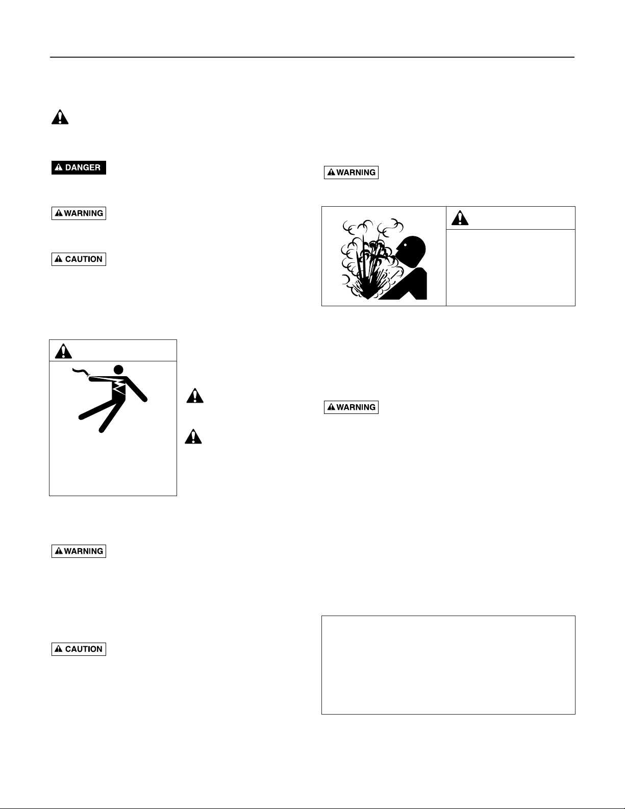
ELECTRICAL SAFETY
Capacitor voltage may be hazardous. To
discharge motor capacitor, hold insulated
handle screwdriver BY THE HANDLE and short capacitor
terminals together. Do not touch metal screwdriver blade
or capacitor terminals. If in doubt, consult a qualified
electrician.
GENERAL SAFETY
Do not touch an operating motor. Modern
motors may operate at high temperatures. To avoid burns
when servicing pump, allow it to cool for 20 minutes
after shut-down before handling.
Do not allow pump or any system component to freeze.
To do so will void warranty.
Pump water only with this pump.
Periodically inspect pump and system components.
Wear safety glasses at all times when working on pumps.
Keep work area clean, uncluttered and properly lighted;
store properly all unused tools and equipment.
Keep visitors at a safe distance from the work areas.
Pump body may explode if used as a boost-
er pump unless relief valve capable of passing full pump
flow at 5 Bars (75 psi) is installed.
BOOSTER PUMP INSTALLATIONS:
• Have a vertical depth between the pump and the
water being pumped of 16’ (5m) or less.
• Have one pipe from the well to the pump case.
REPLACING AN OLD PUMP
Hazardous voltage. Disconnect power to
pump before working on the pump or motor.
1. Drain and remove the old pump. Check the old pipe
for scale, lime, rust, etc., and replace it if necessary.
2. Install the pump in the system. Make sure that all
pipe joints in the suction pipe are air-tight as well as
water tight.
If the suction pipe can suck air, the
pump cannot lift water from the water source.
3. Adjust the pump mounting height so that the plumb-
ing connections do not put a strain on the pump
body. Support the pipe so that the pump body does
not take the weight of piping or fittings.
You have just completed the plumbing for your new
pump.
WARNING
Hazardous voltage. Can
shock, burn, or cause death.
Plug pump into a GFCI protect-
ed, grounded electrical outlet.
Unplug pump before working on
pump or system.
WARNING
Hazardous pressure!
Install pressure relief
valve in discharge pipe.
Release all pressure on
system before working on
any component.
Sealing Pipe Joints
Use only teflon tape for making all threaded connections
to the pump itself. Do not use pipe joint compounds on
plastic: they can react with the plastic. Make sure that all
pipe joints in the suction pipe are air tight as well as
water tight.
If the suction pipe can suck air, the pump
will not be able to pull water from the water source.

Installation / Electrical 3
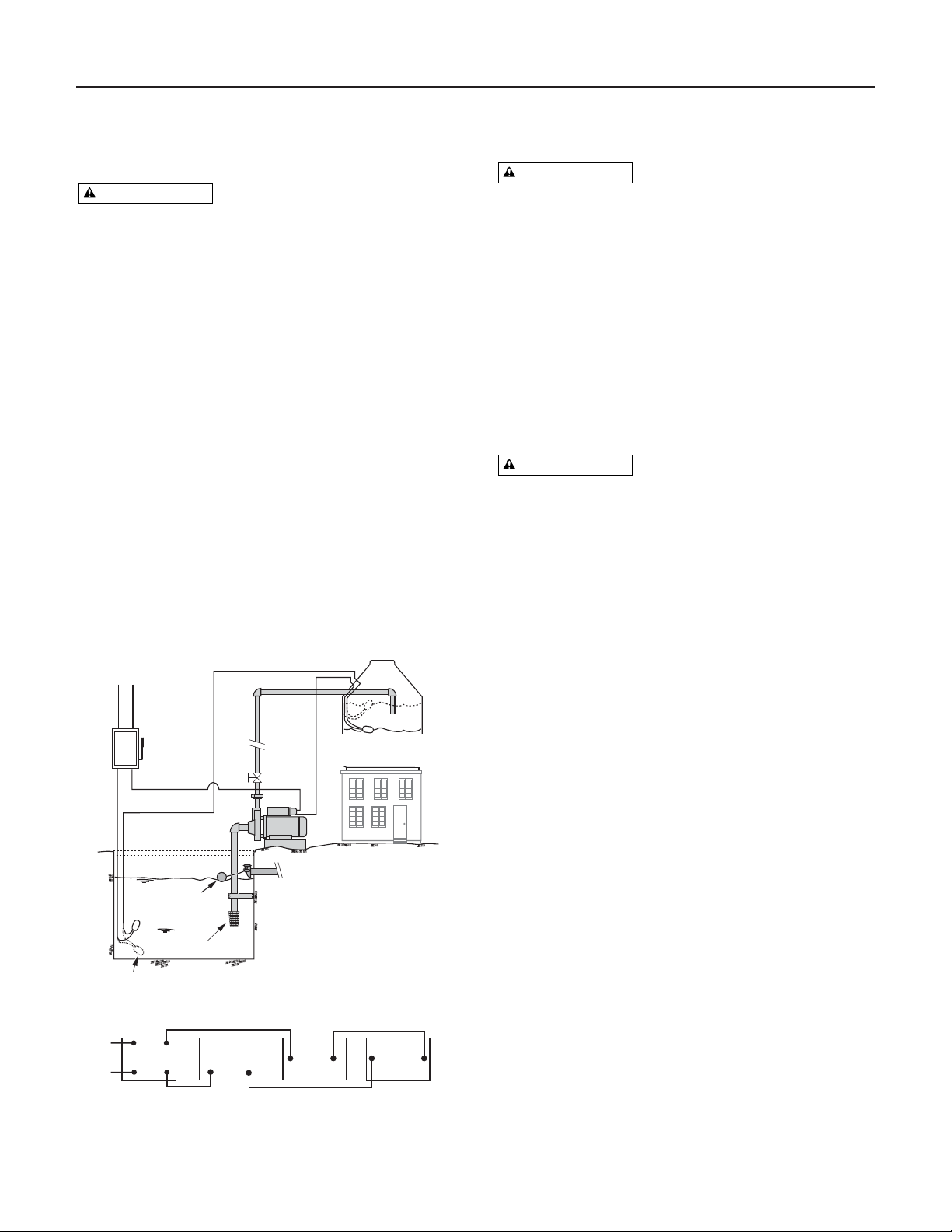
INSTALLATION WITH A ROOFTOP
RESERVOIR TANK (FIGURE 1)
Hazardous voltage. Disconnect power to
pump before working on the pump or motor.
1. Close the shutoff valve between the roof-top tank
and the pump.
2. If there is a valve in the pipe going from the pump
into the house, close that valve also.
3. Loosen the unions near the pump and allow the sys-
tem to drain. Disconnect the unions and remove the
old pump from the system.
4. Clean up the existing piping or replace it with all
new piping around the pump.
5. Reassemble the piping and unions with the new
pump in place. Use teflon tape to seal the joints.
6. Open the isolation valves that you closed in Steps 1
and 2. Also open or loosen the priming plug to allow
air to vent from the system.
7. When solid water runs from the pump’s priming
port, tighten the plug until it seals.
8. Check the system for leaks.
You have just completed the suction pipe plumbing for
your new pump.
ELECTRICAL
Hazardous voltage. Risk of dangerous or
fatal electric shock. Plug the pump into a 115 Volt, 60
Cycle, Ground Fault Circuit Interrupter (GFCI) protect-
ed grounded outlet only. Do not modify or remove the
plug. Make sure the pump circuit meets all codes and
ordinances that apply. To avoid dangerous electrical
shock hazard, keep the cord dry at all times.
For instructions on wiring the pump, refer to the decal
inside the control box.
Lubrication
The motor is lubricated at the factory for the life of
the bearings. The pump seal is water cooled and self
lubricating.
Pump Service
Hazardous voltage. Can shock, burn, or
cause death. Unplug the pump before servicing it. Do not
handle the pump or attempt to work on the pump with
wet hands or while standing on a wet or damp floor.
The motor has an auto-reset thermal overload protector.
If the motor overheats, the overload will cut off the
power to prevent damage and will reset after the motor
cools. If the overload trips repeatedly, check the pump
for the cause (low voltage, a clogged impeller, etc.).
Circuit
Breaker
Box
115 VAC
115V
Hot
Hot
Neutral
Neutral
Black
Black
Brown
City Water Inlet
Float Switch:
Up = On
Down = Off
Foot Valve
Cistern
Pump
Tinaco
Float Switch:
Up = Off
Down = On
Circuit
Breaker
Box
Neutral Neutral – Black
Cistern Float
Switch
Hot
Pum p
Hot – Brown
Tinaco
Float Switch
Wiring Connections – Schematic
Float Valve
Figure 1 – Rooftop Reservoir (Tinaco) Installation.

Troubleshooting 4
SYMPTOM POSSIBLE CAUSE(S) CORRECTIVE ACTION
Motor will not run Disconnect switch is off Be sure switch is on.
Fuse is blown or circuit breaker tripped Replace fuse or reset circuit breaker.
Wires at motor are loose, DISCONNECT POWER; check and tighten all wiring.
disconnected, or wired incorrectly
Pressure switch contacts are dirty DISCONNECT POWER and clean the electrical contacts.
Motor runs hot and Voltage is too low Check with power company. Install heavier wiring if wire size is too small.
overload kicks off Pump cycles too frequently See section below on too frequent cycling.
Motor runs but no Pump in new installation did In new installation:
water is delivered* not pick up prime through:
1. Improper priming 1. Re-prime according to instructions.
2. Air leaks 2. Check all connections on suction line with
shaving cream.
3. Leaking foot valve or check valve 3. Replace foot valve or check valve.
Pump has lost prime through: In installation already in use:
1. Air leaks 1. Check all connections on suction line and well seal.
2. Water level below suction pipe inlet 2. Lower suction line into water and re-prime. If receding water level
in well exceeds 16’ (5M), a deep well pump is needed.
Foot valve or strainer is plugged Clean foot valve or strainer.
Ejector or impeller is plugged Clean ejector or impeller (See Repair Parts page).
Check valve or foot valve is stuck shut Replace check valve or foot valve.
Pipes are frozen Thaw pipes. Bury pipes below frost line. Heat pit or pump house.
Foot valve and/or strainer are Raise foot valve and/or strainer above bottom of water source.
buried in sand or mud Clean foot valve and strainer.
Water level is too low for shallow well A deep well pump may be needed (over 16’ (5M) to water)
setup to deliver water to deliver water.
Pump does not Water level in well is lower than A deep well jet will be needed if your well is more than 16’ (5M)
deliver water to full estimated depth to water.
capacity Steel piping (if used) is corroded or Replace with plastic pipe where possible, otherwise with new steel pipe.
limed, causing excess friction
Piping is too small in size Use larger piping.
Packed well point Backflush well point or sink new point.
Pump delivers water but
Float switch is out of adjustment or DISCONNECT POWER; adjust or replace float switch.
does not shut off or contacts are welded together
pump cycles too Faucets have been left open Close faucets.
frequently Impeller is clogged Clean impeller.
Pipes leak Check connections.
Foot valves leak Replace foot valve.
Air spurts from faucets Pump is picking up prime When pump has picked up prime, it should pump solid water with no air.
Leak in suction side of pump Suction pipe is sucking air. Check joints for leaks with shaving cream.
Well is gaseous Consult factory about installing a sleeve in the well.
Intermittent over-pumping of well Lower foot valve if possible, otherwise restrict pump discharge.
(Water drawn down below foot valve)
* (Note:
Stop pump;
then check prime
before looking for
other causes.
Unscrew
priming
plug and see if water
is in priming hole).
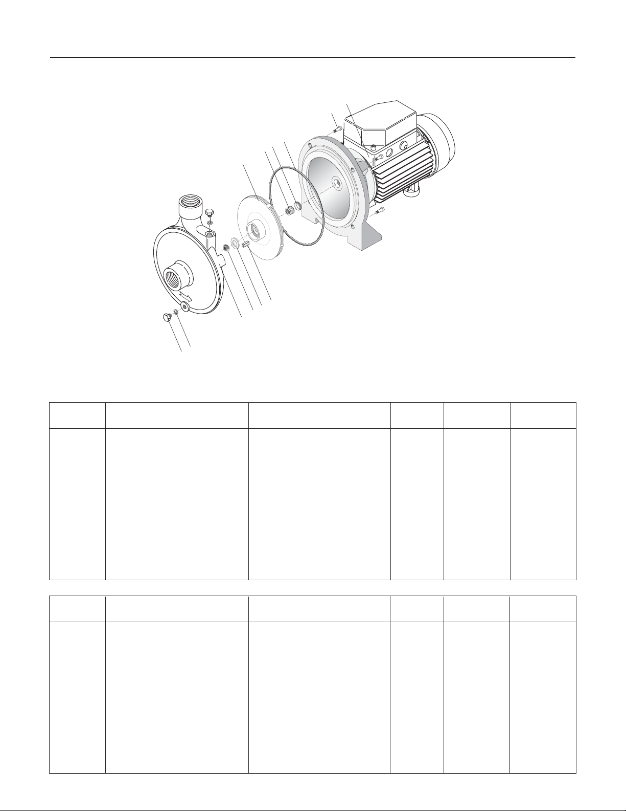
Repair Parts 5
128
79
6
54
3
2
1
11
10
5241 1205
Key No. Part Descripción No. Used CM025 CM050
Clave No. Description de la pieza Cantidad 1/4 HP 1/2 HP
1 Motor Motor 1 300E0300 300E310
2 Capscrew Tornillo prisionero 4 100A0120 100A0120
3 O-Ring Aro tórico 1 300B0500 300B0500
4 Ceramic Seal Half Mitad de cerámica de la junta 1 300D0100 300D0100
5 Carbon Seal Half Mitad de carbón de la junta 1 300D0101 300D0101
6 Impeller Impulsor 1 300F0400 300F0410
7 Washer Arandela 1 300A0300 300A0300
8 Nut, Impeller Tuerca, impulsor 1 300A0200 300A0200
9 Shaft Key Llave del eje 1 100D0500 100D0500
10 Pipe Plug Tapón del tubo 2 100A0130 100A0130
11 Plastic Washer Arandela de plástico 2 100B0100 100B0100
12 Volute Voluta 1 300F0100 300F0100
Repair Parts / Refacciones
Key No. Part Descripción No. Used CM075 CM100
Clave No. Description de la pieza Cantidad 1/4 HP 1/2 HP
1 Motor Motor 1 300E320 300E330
2 Capscrew Tornillo prisionero 4 100A0125 100A0125
3 O-Ring Aro tórico 1 300B0510 300B0510
4 Ceramic Seal Half Mitad de cerámica de la junta 1 300D0110 300D0110
5 Carbon Seal Half Mitad de carbón de la junta 1 300D0111 300D0111
6 Impeller Impulsor 1 300F0420 300F0430
7 Washer Arandela 1 300A0300 300A0300
8 Nut, Impeller Tuerca, impulsor 1 300A0200 300A0200
9 Shaft Key Llave del eje 1 100D0500 100D0500
10 Pipe Plug Tapón del tubo 2 100A0130 100A0130
11 Plastic Washer Arandela de plástico 2 100B0100 100B0100
12 Volute Voluta 1 300F0110 300F0110

Warranty 6
ATTACH ORIGINAL RECEIPT HERE FOR WARRANTY CONSIDERATION.
SIMER warrants to the original consumer purchaser (“Purchaser”) of its products that they are free from defects in material or workmanship.
If within twelve (12) months from the date of the original consumer purchase any such product shall prove to be defective, it shall be repaired or
replaced at SIMER’s option, subject to the terms and conditions set forth below. Your original receipt of purchase is required to determine warranty
eligibility.
Exceptions to the Twelve (12) Month Warranty
Product/Model No. Warranty Period
M40P, M40, BW85P, CM10, CMK 90 days
2330, 2300, 2310, 2955, 2956, 2957, 2960, A5500 2 Years
4" Submersible Well Pumps, 3984, 3983, 2975PC, 2958, 2985, 3075SS 3 Years
Pre-Charge Water System Tank, 3986, 3985, 2956, 2960 5 Years
3988, 3995, 3997, 3963 Lifetime
General Terms and Conditions
Purchaser must pay all labor and shipping charges necessary to replace product covered by this warranty. This warranty shall not apply to
acts of God, nor shall it apply to products which, in the sole judgement of SIMER, have been subject to negligence, abuse, accident, misap-
plication, tampering, alteration; nor due to improper installation, operation, maintenance or storage; nor to other than normal application, use
or service, including but not limited to, operational failures caused by corrosion, rust or other foreign materials in the system, or operation at
pressures in excess of recommended maximums.
Requests for service under this warranty shall be made by returning the defective product to the Retail outlet or to SIMER as soon as possi-
ble after the discovery of any alleged defect. SIMER will subsequently take corrective action as promptly as reasonably possible.No
requests for service under this warranty will be accepted if received more than 30 days after the term of the warranty.
This warranty sets forth SIMER’s sole obligation and purchaser’s exclusive remedy for defective products.
SIMER SHALL NOT BE LIABLE FOR ANY CONSEQUENTIAL, INCIDENTAL, OR CONTINGENT DAMAGES WHATSOEVER.
THE FOREGOING WARRANTIES ARE EXCLUSIVE AND IN LIEU OF ALL OTHER EXPRESS WARRANTIES. IMPLIED WARRANTIES,
INCLUDING BUT NOT LIMITED TO THE IMPLIED WARRANTIES OF MERCHANTABILITY AND FITNESS FOR A PARTICULAR PUR-
POSE, SHALL NOT EXTEND BEYOND THE DURATION OF THE APPLICABLE EXPRESS WARRANTIES PROVIDED HEREIN.
Some states do not allow the exclusion or limitation of incidental or consequential damages or limitations on how long an implied warranty
lasts, so the above limitations or exclusions may not apply to you. This warranty gives you specific legal rights and you may also have other
rights which vary from state to state.
SIMER • 293 Wright Street • Delavan, WI U.S.A. 53115
Phone: 1-800-468-7867/1-800-546-7867 • Fax: 1-800-390-5351
Seguridad 7
¡LEA Y SIGA LAS
INSTRUCCIONES DE SEGURIDAD!
Este es el símbolo de alerta de seguridad. Cuando vea
este símbolo en su bomba o en este manual, busque
alguna de las siguientes palabras de advertencia y esté alerta a
la posibilidad de heridas personales:
PELIGRO advierte acerca de los peligros que
provocarán lesiones personales graves, muerte o daños materi-
ales considerables si se ignoran.
advierte acerca de los peligros que
pueden provocar lesiones personales graves, muerte o daños
materiales considerables si se ignoran.
advierte acerca de los peligros que provo-
carán o podrán provocar lesiones personales o daños materi-
ales menores si se ignoran.
La etiqueta AVISO indica instrucciones especiales que son
importantes pero que no están relacionadas con los peligros.
Lea atentamente y siga todas las instrucciones de seguridad en
este manual y en la bomba.
Mantenga las etiquetas de seguri-
dad en buen estado.
Reemplace las etiquetas de
seguridad faltantes o dañadas.
Conecte el motor a
tierra antes de conectar
el suministro de corriente
eléctrica.
El cableado debe cumplir
con todas las normas
correspondientes.
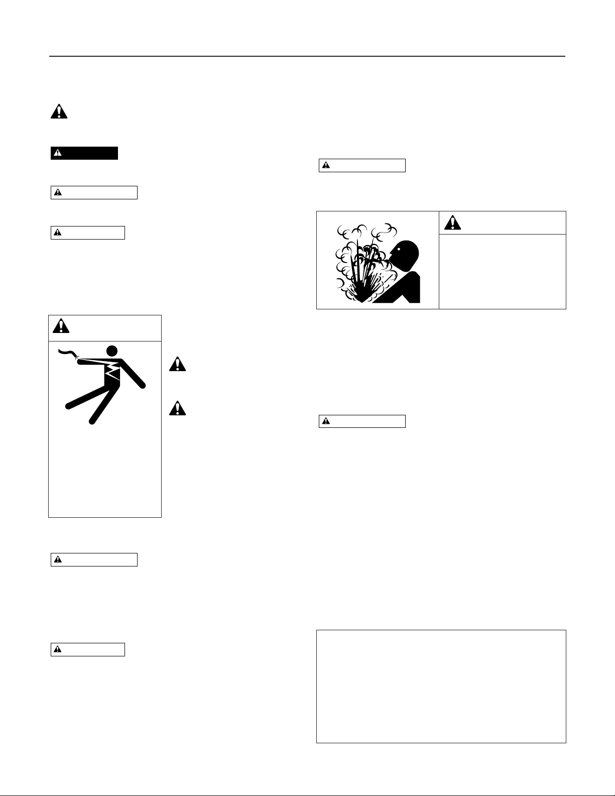
SEGURIDAD ELÉCTRICA
La tensión del capacitor puede ser peli-
grosa. Para descargar el capacitor del motor, tome un
destornillador con mango aislado POR EL MANGO y ponga los
bornes del capacitor en corto circuito. No toque la hoja de
metal del destornillador ni los bornes del capacitor. En caso de
dudas, consulte a un electricista competente.
SEGURIDAD GENERAL
No toque un motor en operación. Los
motores modernos pueden funcionar a alta temperatura. Para
evitar quemaduras durante los trabajos de mantenimiento y ser-
vicio de la bomba, deje que se enfríe por 20 minutos después
de apagarla y antes de manipularla.
No permita que la bomba ni cualquier componente del sistema
se congelen ya que ello invalidará la garantía.
Utilice esta bomba sólo para bombear agua.
Inspeccione la bomba y los componentes del sistema per-
iódicamente.
Use gafas de seguridad siempre que trabaje con bombas.
El área de trabajo se debe mantener limpia, ordenada y con
iluminación adecuada; guarde debidamente las herramientas y
el equipo que no utilice.
Mantenga a los visitantes a una distancia segura de las áreas de
trabajo.
El cuerpo de la bomba puede explotar si
se utiliza como bomba de sobrepresión a menos que se instale
una válvula de desahogo que sea capaz de pasar todo el flujo de
la bomba a 5 baras (75 libras por pulgada cuadrada).
INSTALACIONES DE BOMBAS
REFORZADORAS:
• La profundidad vertical entre la bomba y el agua bombeada
debe ser de 16’ (5 m) o menos.
• Instale una tubería desde el pozo a la caja de la bomba.
REEMPLAZO DE LA BOMBA USADA
Tensión peligrosa. Desconecte la cor-
riente eléctrica a la bomba antes de trabajar con la bomba o
con el motor.
1. Drene y saque la bomba usada. Verifique que las tuberías
antiguas no tengan restos de oxidación, cal, herrumbre, etc.
y cámbielas de ser necesario.
2. Instale la bomba en el sistema. Verifique que todas las
uniones de las tuberías en la tubería de aspiración estén
herméticas y estancas.
Si la tubería de aspiración puede
aspirar aire, la bomba no podrá extraer agua desde la
fuente de suministro de agua.
3. Ajuste la altura de montaje de la bomba para que las
conexiones de plomería no ejerzan presión sobre el cuerpo
de la bomba. Apoye las tuberías de manera que el cuerpo
de la bomba no deba soportar el peso de las tuberías ni de
los accesorios.
Usted acaba de terminar la instalación de la plomería de su
nueva bomba.
ADVERTENCIA
ADVERTENCIA
PRECAUCIÓN
ADVERTENCIA
PRECAUCIÓN
ADVERTENCIA
PELIGRO
ADVERTENCIA
Tensión peligrosa. Puede
causar choque, quemaduras
o muerte.
Enchufe la bomba en un toma-
corriente conectado a tierra y
protegido por un disyuntor de
escape a tierra. Desenchufe la
bomba antes de trabajar en la
misma o en el sistema.
ADVERTENCIA
¡Presión peligrosa!
Instale una válvula de desa-
hogo de presión en la tubería
de descarga.
Descargue toda la presión en el
sistema antes de trabajar con
cualquiera de los componentes.
Cómo sellar las juntas/
uniones de las tuberías
Use sólo cinta de Teflón para todas las conexiones fileteadas a la
bomba. No use compuestos para uniones de tuberías en tuberías
de plástico ya que pueden reacciones con el plástico. Verifique
que todas las uniones de las tuberías en la tubería de aspiración
sean herméticas y estancas.
Si la tubería de aspiración puede
aspirar aire, la bomba no podrá extraer agua desde la fuente de
suministro de agua.
Instalación / Información Eléctrica 8
INSTALACIÓN CON UN TANQUE DE
DEPÓSITO EN EL TECHO (FIGURA 1)
Tensión peligrosa. Desconecte la cor-
riente eléctrica a la bomba antes de trabajar con la bomba o
con el motor.
1. Cierre la válvula de corte entre el tanque del techo y la
bomba.
2. Si hay una válvula en la tubería que va desde la bomba
hacia la casa, ciérrela también.
3. Afloje las uniones cerca de la bomba y permita que se
drene el sistema. Desconecte las uniones y saque la
bomba usada del sistema.
4. Limpie la tubería existente o reemplácela con una tubería
completamente nueva alrededor de la bomba.
5. Vuelva a ensamblar la tubería y las uniones con la nueva
bomba instalada. Use cinta de Teflón para sellar las
uniones.
6. Abra las válvulas de aislamiento que había cerrado en los
Pasos 1 y 2. También abra o afloje el tapón de cebadura
para permitir que el aire salga del sistema.
7. Cuando salga un chorro firme de agua del orificio de
cebadura de la bomba, apriete el tapón hasta que quede
hermético.
8. Verifique que no haya fugas en el sistema.
Usted acaba de terminar la instalación de la plomería de la
tubería de aspiración de su nueva bomba.
INFORMACIÓN ELÉCTRICA
Tensión/voltaje peligroso. Riesgo de
choque eléctrico peligroso o fatal. Enchufe la bomba en un
tomacorriente puesto a tierra de 115 voltios, 60 ciclos, prote-
gido por un disyuntor diferencial (GFCI). Verifique que el cir-
cuito de la bomba cumpla con todas las normas y los
reglamentos que correspondan. Para evitar el riesgo de
choques eléctricos peligrosos, mantenga el cordón seco en
todo momento.
Para instrucciones de cableado de la bomba, ver etiqueta den-
tro de la caja de conexiones.
Lubricación
El motor viene con una lubricación de fábrica que durará por
todo el período de vida útil de los cojinetes. El sello de la
bomba es autolubricante y de enfriamiento por agua.
Servicio de la bomba
Tensión/voltaje peligroso. Puede
provocar choques, quemaduras o muerte. Desenchufe la
bomba antes de realizar trabajos de mantenimiento o de
reparación. No manipule ni trate de trabajar en la bomba
con manos mojadas o mientras esté parado sobre un piso
mojado o húmedo.
El motor tiene un protector contra sobrecarga térmica que se
reposiciona automáticamente. Si el motor se recalienta, la
sobrecarga cortará la corriente eléctrica para impedir que
ocurran daños y se reposicionará una vez que se haya enfria-
do el motor. Si el dispositivo de sobrecarga se dispara repeti-
damente, inspeccione la bomba para determinar la causa (baja
tensión, impulsor obstruido, etc.).
ADVERTENCIA
ADVERTENCIA
ADVERTENCIA
Caja de
disyuntores
115 VCA
115 V
Alimentation
Caliente
Neutro
Neutro
Negro
Negro
Marrón
Admisión de las aguas públicas
Interruptor de flotador:
Hacia arriba - encendido
Hacia abajo - apagado
Válvula de pie
Cisterna
Bomba
Tinaco
Caja de
disyuntores
Neutro Neutro – Negro
Interruptor de
flotador de la
cisterna
Caliente
Bomba
Caliente – Marrón
Interruptor
de flotador
de Tinaco
Conexiones de los cables – Esquemático
Válvula
de flotador
Interruptor de flotador:
Hacia arriba - apagado
Hacia abajo - encendido
Figura 1 - Instalación con tanque de techo (Tinaco).

Localización de fallas 9
SÍNTOMA CAUSA(S) PROBABLE(S) ACCIÓN CORRECTIVA
El motor no funciona El interruptor de desconexión está apagado
El fusible está quemado o el disyuntor se abrió
Los cables en el motor están sueltos,
desconectados o conectados incorrectamente
Los contactos del manóstato están sucios
Asegúrese de que el manóstato esté encendido.
Reemplace el fusible o reposicione el disyuntor.
DESCONECTE LA CORRIENTE ELÉCTRICA; inspeccione y apriete todos los cables.
DESCONECTE LA CORRIENTE ELÉCTRICA y lime los contactos eléctricos.
El motor se calienta y
dispara la sobrecarga
El motor funciona pero
no sale agua*
La bomba no
produce agua a
toda su capacidad
La bomba entrega agua
pero no se apaga o los
ciclos de bombeo son
demasiado frecuentes
Sale aire de los grifos Cuando la válvula está cebando, se expulsa todo el aire.
La tubería de aspiración está aspirando aire. Verifique que no haya fugas en las juntas
usando crema de afeitar.
Consulte a la fábrica sobre la instalación de una camisa en el pozo.
Baje la válvula de pie si es posible, de lo contrario, restrinja la descarga de la bomba.
El interruptor de flotador está desajustado o
los contactos se han soldado juntos
Se dejaron las llaves abiertas
El impulsor está tapado
Las tuberías presentan fugas
Las válvulas de pie presentan fugas
DESCONECTE LA CORRIENTE ELÉCTRICA; ajuste o reemplace el interruptor de
flotador.
Cierre las llaves.
Limpie el impulsor.
Inspeccione las conexioness.
Reemplace la válvula de pie.
El nivel del agua en el pozo profundo es
menor que el que se calculó
La tubería de acero (si se utilizó) está corroída
u oxidada, ocasionando una fricción excesiva
El tamaño de la tubería es muy pequeño
Punto filtrante obstruido.
Se necesitará un chorro para pozos profundos si la profundidad de su pozo es mayor
que 16 pies (5 m) al agua.
Reemplace con tubería de plástico donde sea posible, o de lo contrario con tubería
nueva de acero.
Utilice tubería más grande.
Lave el punto filtrante o hinque uno nuevo.
La bomba en una instalación nueva no
recogió el cebado debido a:
1. Cebado inadecuado
2. Fugas de aire
3. Fugas en la válvula de pie o en la válvula
de retención
La bomba ha perdido cebado debido a:
1. Fugas de aire
2. Nivel de agua por debajo de la entrada
de la tubería de aspiración
La válvula de pie o el colector están tapados
El eyector o el impulsor están tapados
La válvula de retención o la válvula de pie
están cerradas y atascadas
Las tuberías están congeladas
La válvula de pie y/o el colector están
enterrados en arena o en lodo
El nivel de agua es demasiado bajo para que
la instalación para pozo poco profundo
entregue agua
En una instalación nueva:
1. Vuelva a cebarla según las instrucciones.
2. Revise todas las conexiones en la línea de aspiración con crema de afeitar.
3. Reemplace la válvula de pie o la válvula de retención.
En una instalación que ya esté en uso:
1. Inspeccione todas las conexiones en la línea de aspiración y en el sello del eje.
2. Baje la línea de aspiración hacia el agua y vuelva a cebar. Si la disminución del
nivel de agua supera los 16 pies (5 m), será necesario instalar una bomba para
pozo profundo.
Limpie la válvula de pie o el colector.
Limpie el eyector o el impulsor (consulte la página de Refacciones).
Reemplace la válvula de retención o la válvula de pie.
Descongele las tuberías. Entierre las tuberías debajo de la línea de congelación.
Caliente el recinto de bombas o el foso.
Eleve la válvula de pie y/o el colector por encima del fondo de la fuente de agua.
Limpie la válvula de pie y el colector.
Posiblemente requiera una bomba para pozos profundos (más de 16 pies - 5 m - al
agua) para entregar agua.
La tensión es muy baja
Los ciclos de la bomba son muy frecuentes
Verifique con la compañía de energía eléctrica. Instale un cableado de mayor calibre
si éste es muy pequeño.
Consulte la sección a continuación sobre ciclos demasiado frecuentes.
La bomba está cebando
Fuga del lado de la aspiración de la bomba
El pozo es gaseoso
Sobre-bombeo intermitente del pozo, (agua
extraída por debajo de la válvula de pie)
* (Nota:
Detenga la
bomba:
después veri-
fique el cebado antes
de buscar otras causas.
Destornille el tapón de
cebadura y vea si hay
agua en el orificio de
cebadura)

Garantía 10
ADHÍERA AQUÍ EL RECIBO ORIGINAL PARA VALIDACION DE GARANTÍA
SIMER garantiza al comprador consumidor original (“Comprador”) de sus productos, que éstos se encuentran libres de defectos de material o mano de
obra
.
Si dentro de los doce (12) meses de la fecha original de la compra cualquiera de los productos demostrara estar defectuoso, el mismo será reparado
o reemplazado, a opción de
SIMER
con sujeción a los términos y condiciones expuestos a continuación. Se requiere su recibo original de compra para
determinar si se encuentra bajo garantía.
Excepciones a la Garantía por Doce (12) Meses
Producto/Modelo No. Período de garantía
M40P, M40, BW85P, CM10, CMK 90 días
2330, 2300, 2310, 2955, 2956, 2957, 2960, A5500 2 años
4" Submersible Well Pumps, 3984, 3983, 2975PC, 2958, 2985, 3075SS 3 años
Pre-Charge Water System Tank, 3986, 3985, 2956, 2960 5 años
3988, 3995, 3997, 3963 De por vida
Términos y Condiciones Generales
El comprador debe pagar todos los gastos de mano de obra y transporte necesarios para reemplazar el producto cubierto por esta garantía. Esta
garantía no se aplicará a hechos de fuerza mayor, ni se aplicará a los productos que, a juicio exclusivo de
SIMER
, hayan sido objeto de negligen-
cia, abuso, accidente, aplicaciones contraindicadas, manejo indebido, alteraciones; ni debido a instalación, funcionamiento, mantenimiento o alma-
cenaje incorrectos; ni a ninguna otra cosa que no sea su aplicación, uso o servicio normales, incluyendo, pero no limitado a, fallas operacionales
causadas por corrosión, oxidación u otros elementos extraños en el sistema, o funcionamiento a presión por encima del máximo recomendado.
Los pedidos de servicio bajo los términos de esta garantía serán efectuados mediante la devolución del producto defectuoso al Vendedor o a
SIMER
,
tan pronto como sea posible, después de localizado cualquier supuesto defecto.
SIMER
tomará luego acción correctiva, tan pronto como sea razo-
nablemente posible. Ningún pedido de servicio bajo esta garantía será aceptado si se recibe más de 30 días después del término de la garantía.
Esta garantía establece la obligación única de
SIMER
y el remedio exclusivo del comprador en el caso de productos defectuosos.
SIMER
NO SERÁ RESPONSABLE POR NINGÚN DAÑO CONSECUENTE, INCIDENTAL O CONTINGENTE DE NINGUNA NATURALEZA.
LAS GARANTÍAS ANTERIORES SON EXCLUSIVAS Y REEMPLAZAN CUALESQUIERA OTRAS GARANTÍAS EXPRESAS. LAS
GARANTÍASIMPLÍCITAS, INCLUYENDO, PERO NO LIMITADAS A, LAS GARANTÍAS IMPLÍCITAS DE COMERCIABILIDAD Y APTITUD PARA UN
PROPÓSITO EN PARTICULAR, NO DEBERÁN EXCEDER EL PERÍODO DE DURACIÓN DE LAS GARANTÍAS EXPRESAS APLICABLES AQUÍ
PROVISTAS.
Algunos estados no permiten la exclusión o limitación de daños incidentales o consecuentes ni las limitaciones respecto a la duración de garantí-
as implícitas; de modo que las limitaciones o exclusiones precedentes pueden no aplicarse en su caso. Esta garantía le concede derechos legales
específicos. Usted puede tener, además, otros derechos que varían de un estado a otro.
SIMER • 293 Wright Street • Delavan, WI U.S.A. 53115
Teléfono: 1-800-468-7867/1-800-546-7867 • Fax: 1-800-390-5351
Table of contents
Languages:
Other Simer Water Pump manuals


Popular Water Pump manuals by other brands


POWEL-FLO
POWEL-FLO PFV512 Installation, service & parts manual

Grundfos
Grundfos CMBE instructions

Flextailgear
Flextailgear HT-767 Operation instructions

GORMAN-RUPP
GORMAN-RUPP PAH SERIES Installation, operation, and maintenance manual with parts list

Warren rupp
Warren rupp SANDPIPER F15 Service & operating manual

Westfalia
Westfalia 81 77 21 instruction manual


