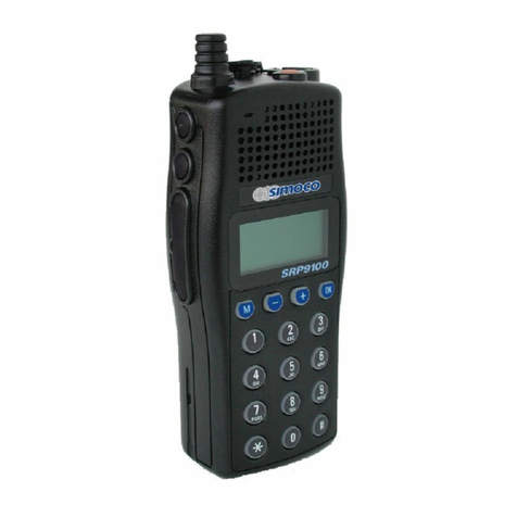
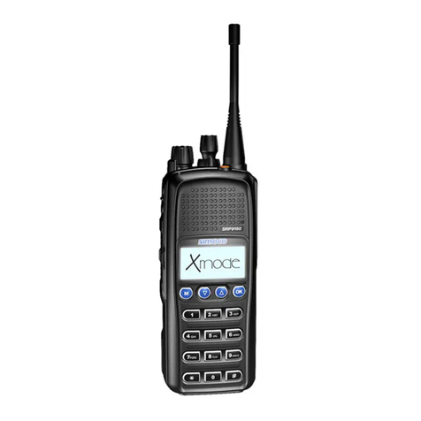
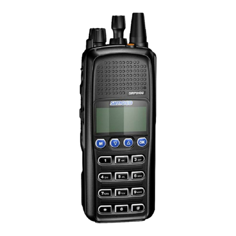
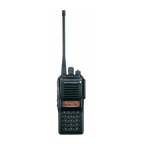
Simoco SDP560 User manual

SDP560 PORTABLE RADIO
BRIEF USER GUIDE
TNM-U-E-0185
ISSUE 1.0
INTRODUCTION
The SDP560 portable radio is a rugged, lightweight radio and provides extended communication
range and excellent sound quality.
The SDP560 portable radio features many customisable parameters to suit
individual requirements. Menus and Key Functions can be configured to
customer requirements.
For greater operational functional detail, refer to the main User Guide, TNM-U-E-0186.
BEFORE USE
Antenna Installation
Place the antenna over the radio’s antenna connector and rotate the antenna
clockwise to engage the antenna connector thread. Continue rotating until tight.
CAUTION
Over tightening the antenna may cause damage to the antenna or connector, which
in turn may affect the radio’s performance.
Installing the Battery Pack
Ensure the ON/OFF volume knob is set to the OFF position.
1. Align the top of the locating tabs on the battery
pack to the bottom of the locating slots on the
radio.
2. Slide the battery pack upwards until the battery
latch clicks into place.
Removing the Battery Pack
Ensure the ON/OFF volume knob of the radio is set
to OFF position.
1. Press and hold down the battery latch.
2. Slide the battery pack downwards until the battery
locating tabs disengages from the radio locating
slots, which then allows the battery to be separated
from the radio.
Charging Instructions
New batteries or batteries that have been inactive for a long time should be fully charged before placed into
service. When the battery pack requires charging, the battery icon on the LCD will blink and the radio will sound a
high pitch tone every second.
The power supply is compatible with a wide AC supply voltage range, and is therefore provided with plugs for
multiple regions. Fit the appropriate plug to the power supply.
Plug the power supply cord into the desktop base, and then plug the power supply itself into the electricity power
outlet.
The standard desktop charger has two slots for charging:
To recharge a portable radio with a battery fitted, turn off the radio and insert it into the front slot of the charger.
To recharge a standalone battery, insert the battery into the rear
slot of the charger.
The green LED on the charger illuminates when the battery has
been charged to 90% capacity. If 100% capacity is required, then
continue recharging the battery for another 30 minutes.
A tri-color LED on the charger pocket provides an at-a-glance
display of the charging status as follows
Status LED
Charging Solid Red
Charged Solid Green
Error Blinking Red
Battery too hot Solid Orange
Basic Operation
On/Off Volume Switch
Turn the volume knob clockwise until a click is heard
to turn the radio on.The audio volume level can be
increased by turning the volume knob further
clockwise. To turn the radio off, turn the volume knob
fully counter-clockwise until a click is heard,
Channel Select Switch
Channel numbers are pre-programmed using a
personal computer and Simoco’s Field Personality
Programmer (FPP) software. Turn the channel select
Switch knob clockwise to select the next channel. Turn
the knob switch counter-clockwise to select the
previous channel. Channels can be organised into
multiple zones. Use the keypad buttons on front of the
radio to change zone through use of the appropriate
menu function.

LCD Display
1
A signal icon resembling an antenna is on while the radio receives an RF signal. A 4-level bar graph to the right of
this icon indicates the strenght of the received signal. A strong signal will turn ON all 4 segments of the signal
strength indicator bar.
2The transmitting power indicator displays “L” during low RF power mode, and “H” during High high RF power
mode.
3The 2Tone or 5Tone mode icon (L) is displayed when the current selected channel has been programmed for
2Tone, 5Tone operation.
4The VOX icon displays “VOX” when the VOX mode has been activated.
5The Scrambler icon displays “SCR” when the scrambler function has been activated.
6The Compander icon is displayed when the compander function has been activated.
7The Alert icon displays “♫” if the radio has been set to play alert tones. This icon will be OFF when alert tones
have been deactivated.
8The Lock icon displays when the keypad has been locked.
9
The Battery icon displays the capacity remaining in the battery using a 3-segment bar graph. A fully charged
battery will display all three segments. Bar graph segments are progressively turned OFF as battery capacity is
being consumed, with a flat battery being indicated by a battery icon with no bar graph segments. The battery
indicator will blink when battery capacity is very low and the battery needs to be recharged.
10
The dot matrix displays 14 alphanumeric characters per line. LCD backlighting can be programmed to turn on
when a button is pressed, after which it will remain on for the programmed length of time after the button has
been released. Alternatively, LCD backlighting can also be programmed to always remain off.
IMPORTANT SAFETY WARNINGS
Accessory Warnings
Use only approved SIMOCO batteries.
SDP560 portable radio equipment is only to be connected to Simoco approved chargers and accessories.
Battery connection, disconnection, and charging must only be carried out in non-hazardous areas.
Metal belt clips must NOT be used in hazardous areas.
Approved accessories may only be connected and disconnected outside hazardous areas.
General Warnings:
Do NOT operate your radio in an explosive atmosphere
Do NOT operate the radio if the antenna has become disconnected or damaged.
Do NOT touch the antenna while the radio is transmitting.
Obey the 'Turn Off Two-way Radios' signs where these are posted, e.g. on a petrol station forecourt.
Do NOT operate your portable radio without a hands-free kit whilst driving a vehicle.
Do NOT use or store the battery above +60 °C.
Do NOT dispose of batteries in a fire.
To Make a Call
The radio switches to transmit mode when the user
presses and holds the PTT button on the right side of
the radio. The status indicator LED lights red whilist
the radio is transmitting. For optimal sound quality
Simoco recommends positioning the microphone
approximately 7-10cm in front of the user’s mouth
whilst talking normally. The radio returns to receive
mode when the user releases the PTT button.
Emergency
The radio can be configured to declare an emergency
when the “Emergency” button is pressed and held. The
person to call when an emergency is declared, the
channel to use for the emergency call, as well as the
radio’s behaviour whilst in emergency mode is highly
configurable. Contact your system administrator for
details on how emergency has been configured on
your radio terminal
Speaker Microphone Jack
The speaker microphone jack on the left side of the
radio is used for connecting external speaker
microphones or similar audio accessories. It is also
used for programming the radio using Simoco’s Field
Personality Programmer (FPP) software and
programming cable.
Indicators
A tri-color LED provides an at-a-glance display of the
SDP560 portable radio’s current status as follows: of
Solid Red: Transmitting.
Solid Green: Receiving.
Blinking Green: Selected channel is occupied by
another conversation. Such conversations will not be
audible if they use of a differently coded squelch than
programmed for the current selected channel.
Blinking Red: Battery is low (Accompanied by an
occasional , alert tone.
Blinking Orange: Cloning mode
(During programming),.
Default Keypad Operation
Menu / Enter / Select
Escape / Go Back
Previous Channel / Menu Entry
Next Channel / Menu Entry
Customisable button
Customisable button
PTT The radio is switched to transmit mode
when the user presses and holds the PTT
Contact your system administrator for details on how the customisable buttons have been
configured on your radio terminal.

FCC Statement
This equipment has been tested and found to comply with the
limits for a Class B digital device, pursuant to part 15 of FCC
Rules. These limits are designed to provide reasonable
protection against harmful interference in a residential
installation. This equipment generates and can radiate radio
frequency energy. If not installed and used in accordance with
the instructions, it may cause harmful interference to radio
communications. However, there is no guarantee that
interference will not occur in a particular installation.
Verification of harmful interference by this equipment to
radio or television reception can be determined by turning it
off and then on. The user is encouraged to try to correct the
interference by one or more of the following measures:
zReorient or relocate the receiving antenna. Increase the
separation between the equipment and receiver.
zConnect the equipment into an outlet on a different
circuit to that of the receiver's outlet.
zConsult the dealer or an experienced radio/TV technician
for help.
Operation is subject to the following two conditions:
zThis device may not cause harmful interference.
zThis device must accept any interference received,
including interference that may cause undesired
operation.
Note: Changes or modifications to this unit not expressly
approved by the party responsible for compliance could void
the user's authority to operate the equipment.
RF Exposure Compliance and
Control Guidelines and Operating
Instructions
To control your exposure and ensure compliance with the
occupational/controlled environmental exposure limits,
always adhere to the following procedures.
Guidelines:
Do not remove the RF Exposure Label from the device.
User awareness instructions should accompany device
when transferred to other users.
Do not use this device if the operational requirements
described herein are not met.
Operating Instructions:
Transmit no more than therated duty factor of50% of the
time. To transmit (talk), push the Push-To-Talk (PTT)
key. To receive calls, release the PTT key. Transmitting
50% of the time, or less, is important because the radio
generates measurable RF energy only when transmitting
(in terms of measuring for standards compliance).
Keep the radio unit at least 2.5 cm away from the face.
Keeping the radio at the proper distance is important as
RF exposure decreases with distance from the antenna.
The antenna should be kept away fromthe face and eyes.
When worn on the body, always place the radio in a
approved holder, holster, case, or body harness or by use
of the correct clip for this product. Use of
non-approved accessories may result in exposure levels
which exceed the FCC's occupational/controlled
environmental RF exposure limits.
Use of non-approved antennas, batteries, and accessories
causes the radio to exceed the FCC RF exposure
guidelines.
Contact your local dealer for the optional accessories of
the product.
L'exposition aux champs rf de
conformité et de contrôle
d'orientations et instructions
Pour contrôler l'exposition et s'assurer de la
conformité avec les limites d'exposition
professionnelle / environnement contrôlé, toujours
respecter les procédures suivantes.
Lignes directrices:
Ne pas enlever l'étiquette de l'appareil d'exposition
aux radiofréquences.
Sensibilisation des utilisateurs instructions devraient
accompagner dispositif lorsque transférés à d'autres
utilisateurs.
Ne pas utiliser cet appareil si les exigences
opérationnelles décrites ci - après ne sont pas
remplies.
Les instructions de fonctionnement:
Transmettre non plus que le facteur d'utilisation
nominal de 50% du temps.à transmettre (parler),
pousse le pousse à parler (ptt). Pour recevoir des
appels, les ptt.50% du temps de transmission, ou
moins, est important parce que la radio génère de
l'énergie rf seulement lors de la transmission des (en
termes de mesure de la conformité aux normes).
Ie groupe de la radio continue d'au moins 2,5 cm de la
surface.garde la radio à la bonne distance est
important, car l'exposition aux champs rf diminue
Après examen de ce matériel aux conformité aux limites DAS,
ISEDC Statement
The device has been tested and complies with SAR limits,
users can obtain Canadian information on RF exposure and
compliance
et/ou aux limites d’intensité de champ RF, les utilisateurs
peuvent sur l’exposition aux radiofréquences et la conformité
and compliance d’acquérir les informations correspondantes
avec la distance de l'antenne.l'antenne doit se tenir
loin du visage et des yeux.
Quand portés sur le corps, toujours place de
la radio dans un étui, approuvé titulaire, ou un
harnais ou par l'utilisation de lavidéo pour ce
produit.utilisation des accessoires non approuvés
peuvent entraîner des fac qui dépassent les niveaux
d'exposition professionnelle etenvironnementale
contrôlée des limites d'exposition aux rf.
Non approuvé des antennes, les piles et les
accessoires causes la radio à dépasser les lignes
directrices sur l'exposition aux radiofréquences de fac.
Communiquez avec votre distributeur local pour
les accessoires facultatifs du produit.
SAR tests are conducted using standard operating positions accepted by the FCC/ISEDC
with the device transmitting at its highest certified power level in all tested frequency
bands, although the SAR is determined at the highest certified power level, the actual
SAR level of the device while operating can be well below the maximum value.
Before a new model device is a available for sale to the public, it must be tested and
certified to the FCC/ISEDC that it does not exceed the exposure limit established by the
FCC/ISEDC, Tests for each device are performed in positions and locations (worn on
the body)as required by the FCC/ISEDC.
For face-up, 25mm was used for test, this equipment should be installed and
operated with minimum distance 25mm.
For body worn operation, this device has been tested and meets the FCCISEDC/
RF exposure guidelines when used with an accessory designated for this product
or when used with an accessory that Contains no metal.
Non-compliance with the above restrictions may result in violation of RF exposure
guidelines.
Les tests SAR sont effectués en utilisant des positions de fonctionnement standard
acceptées par la FCC/ISEDC avec l'appareil transmettant à son niveau de puissance
certifié le plus élevé dans toutes les bandes de fréquences testées, bien que le
SAR soit déterminé au niveau de puissance certifié le plus élevé, le niveau SAR réel
de l'appareil tout en fonctionnement peut être bien en de?à de la valeur maximale.
Avant qu'un nouveau modèle d'appareil soit disponible à la vente au public, il doit
être testé et certifié par la FCC/ISEDC qu'il ne dépasse pas la limite d'exposition établie
par la FCC/ISEDC. Des tests pour chaque appareil sont effectués dans des
positions et des emplacements (porté sur le corps) comme requis par la FCC/ISEDC.
Pour face vers le haut, 25 mm a été utilisé pour le test, cet équipement doit être
installé et utilisé avec une distance minimale de 25 mm.
Pour un fonctionnement porté sur le corps, cet appareil a été testé et répond
aux directives d'exposition RF FCC/ISEDC lorsqu'il est utilisé avec un accessoire
con?u pour ce produit ou lorsqu'il est utilisé avec un accessoire qui ne contient
pas de métal.
Le non-respect des restrictions ci-dessus peut entra?ner une violation des directives
d'exposition aux RF.
Other Simoco Portable Radio manuals

Simoco
Simoco SRP9180-P25 User manual

Simoco
Simoco SRP8000 SERIES User manual

Simoco
Simoco SDP760 User manual

Simoco
Simoco SRP9170 User manual

Simoco
Simoco SRP9170 User manual

Simoco
Simoco SRP9120 Instruction Manual

Simoco
Simoco SDP650 User manual

Simoco
Simoco SRP9180 P25 User manual

Simoco
Simoco SRP9170 User manual

Simoco
Simoco SDP650 User manual