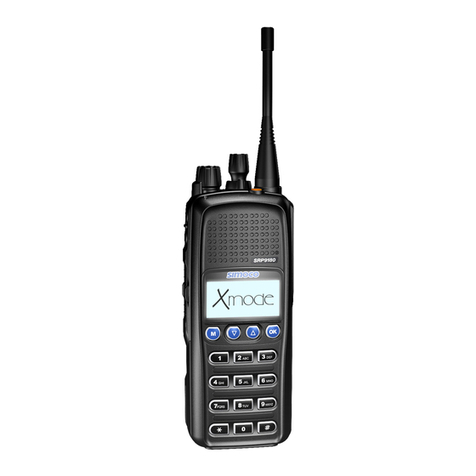
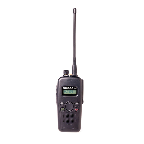
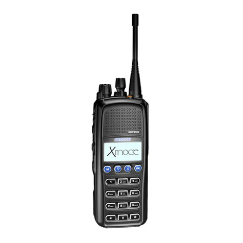
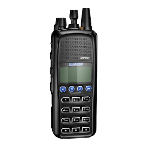
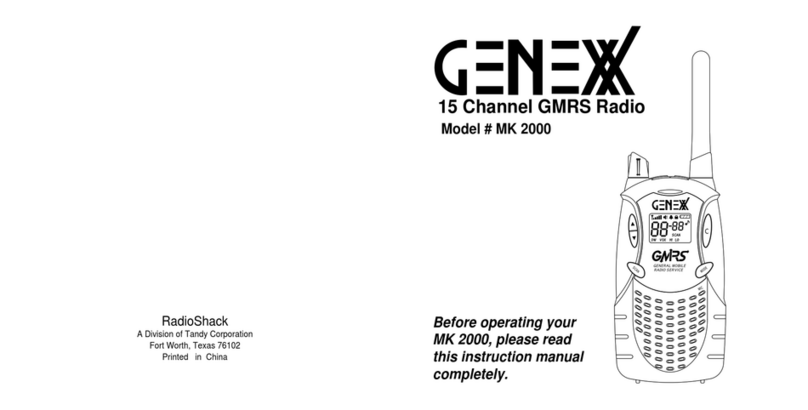
Simoco SRP8000 SERIES User manual

SERVICE MANUAL
TP0332/2
SRP8000 SERIES
VHF/UHF PORTABLE RADIO

Introduction
Simoco Europe Ltd is a leading manufacturer of
professional mobile radio communications with
more than fifty years experience of designing,
manufacturing, installing and maintaining their
product range.
With an enviable pedigree, Simoco Europe Ltd
leads the field for innovation and quality; is fully
committed in design,development and enhanc-
ing standards which included POCSAG and
MPT1327. Simoco is deeply involved in TETRA
digital technology; pioneering itsdevelopment
since 1990.
Simoco's products are backed by a world-wide
capability in system planning, installation and
commissioning,plus an after-sales service
organisation second to none.
The 'Simoco' name is synonymous with
outstanding technological innovation,
achievement and quality for mobile radio
communications systems world-wide that is
wholly dedicated to Customer satisfaction.
intro.fmPage1 Wednesday, August 5, 1998 10:39 AM

TP0332/2 1
The performance figures quoted are subject to normal manufacturing and service tolerances. The right is
reserved to alter the equipment described in this manual in the light of future technical development.
SRP8000 SERIES
VHF/UHF PORTABLE RADIO
SERVICE MANUAL
Publication No. TP0332/2
August 1998
Printed in England
© Simoco Europe Ltd. 1998
All rights reserved. No part of this publication may be
reproduced in any form or by any means without the prior permission of
Simoco Europe Ltd.
WARNING
The Battery Chargers which form partof this equipment are designed to
meet relevant safety requirements.
If it is necessary to replace any safety-conscious component the
correct item MUST be fitted. Ensure that all insulatorsor covers are
fitted after servicing. Check that all warning labels are in place.
If any re-wiring of the mains input supply cables is necessary, the
specified type must be used and alterations tothe routeing or
connections must not be made.
WARNING
NICAD batteries are used with this equipment. They must not be
short-circuited or incinerated. They must be disposed of safely in
accordance with the battery manufacturers’ instructions.
Amendspine.fm Page 1 Wednesday, August 5, 1998 10:42 AM

2TP0332/2
AMENDMENT LIST
Changes made to the equipment described in this publication are published as amendments which
are dated and consecutively numbered.
Reprints will incorporate all amendments, and applicable change notes and service bulletins to date
and entries to this effect will be recorded on the amendment list below.
Each page affected by amendment action will bear the amendment number as a suffix to the
reference number, eg. TP0123/1AM4 indicates that the page has been corrected by amendment
number 4.
The text content of the page that has been affected by the amendment will be indicated by a marker
in the outside margin, starting on the first line and ending on the last line of text affected. This paragraph is
marked as an example.
Amendment packs, where applicable, can be obtained from the Order Desk.
Should it become necessary to raise the issue of a publication, the amendment numbering will
recommence with No. 1.
ERRORS AND OMISSIONS
The usefulness of this publication depends upon its accuracy. Whilst every endeavour has been
made to eliminate errors, some may exist. It is requested therefore that any errors or omissions noted be
advised as follows:
Please quote: Please send to:
(1) Title of publication Simoco Europe Ltd,
(2) TP Ref No Technical Publications Department,
(3) Last amendment No. received. P.O. Box 24,
(4) Page and/or Figure No. in error. St Andrews Road,
Cambridge, CB4 1DP,
England.
Amendment No Date Initials Remarks
July 1998
July 1998 Change Notes up to 25 June 98 actioned in this issue.
Service Bulletins up to 17 July 98 actioned in this issue.

TP0332/2 (i)
SP8000 SERIES
VHF/UHF PORTABLE RADIO
CONTENTS
Page
PRELIMINARY
PRODUCT SUPPORT POLICY. . . . . . . . . . . . . . . . . . . . . . . . . . . . . . . . . . . . . . . . . . . . . . . . . (i)
Sevice Concept. . . . . . . . . . . . . . . . . . . . . . . . . . . . . . . . . . . . . . . . . . . . . . . . . . . . . . . . . . . . . . (i)
Warranty. . . . . . . . . . . . . . . . . . . . . . . . . . . . . . . . . . . . . . . . . . . . . . . . . . . . . . . . . . . . . . . . . . . (i)
Service . . . . . . . . . . . . . . . . . . . . . . . . . . . . . . . . . . . . . . . . . . . . . . . . . . . . . . . . . . . . . . . . . . . . (i)
-ServiceLevel1. . . . . . . . . . . . . . . . . . . . . . . . . . . . . . . . . . . . . . . . . . . . . . . . . . . . . . . . . (i)
-ServiceLevel2. . . . . . . . . . . . . . . . . . . . . . . . . . . . . . . . . . . . . . . . . . . . . . . . . . . . . . . . . (i)
-Service Level 3 . . . . . . . . . . . . . . . . . . . . . . . . . . . . . . . . . . . . . . . . . . . . . . . . . . . . . . . . . (i)
SERVICE BULLETINS . . . . . . . . . . . . . . . . . . . . . . . . . . . . . . . . . . . . . . . . . . . . . . . . . . . . . . . .(ii)
SECTION 1 - GENERAL INFORMATION
INTRODUCTION . . . . . . . . . . . . . . . . . . . . . . . . . . . . . . . . . . . . . . . . . . . . . . . . . . . . . . . . . . . . .1.1
SUMMARY OF DATA. . . . . . . . . . . . . . . . . . . . . . . . . . . . . . . . . . . . . . . . . . . . . . . . . . . . . . . . .1.2
General. . . . . . . . . . . . . . . . . . . . . . . . . . . . . . . . . . . . . . . . . . . . . . . . . . . . . . . . . . . . . . . . . . . .1.2
Receiver. . . . . . . . . . . . . . . . . . . . . . . . . . . . . . . . . . . . . . . . . . . . . . . . . . . . . . . . . . . . . . . .. . .1.2
Transmitter. . . . . . . . . . . . . . . . . . . . . . . . . . . . . . . . . . . . . . . . . . . . . . . . . . . . . . . . . . . . . . . . .1.3
ASSOCIATED EQUIPMENTS. . . . . . . . . . . . . . . . . . . . . . . . . . . . . . . . . . . . . . . . . . . . . . . . . . .1.3
ANCILLARY ITEMS . . . . . . . . . . . . . . . . . . . . . . . . . . . . . . . . . . . . . . . . . . . . . . . . . . . . . . . . . .1.3
EQUIPMENT VARIATION . . . . . . . . . . . . . . . . . . . . . . . . . . . . . . . . . . . . . . . . . . . . . . . . . . . . . .1.4
CTCSS TONE FREQUENCIES . . . . . . . . . . . . . . . . . . . . . . . . . . . . . . . . . . . . . . . . . . . . . . . . . .1.5
SELCALL TONE FREQUENCIES . . . . . . . . . . . . . . . . . . . . . . . . . . . . . . . . . . . . . . . . . . . . . . .1.5
SECTION 2 - COMMISSIONING
UNPACKING. . . . . . . . . . . . . . . . . . . . . . . . . . . . . . . . . . . . . . . . . . . . . . . . . . . . . . . . . . . . . . . .2.1
COMMISSIONING . . . . . . . . . . . . . . . . . . . . . . . . . . . . . . . . . . . . . . . . . . . . . . . . . . . . . . . . . . . .2.1
Warning Label . . . . . . . . . . . . . . . . . . . . . . . . . . . . . . . . . . . . . . . . . . . . . . . . . . . . . . . . . . . . . .2.1
Charging the Battery. . . . . . . . . . . . . . . . . . . . . . . . . . . . . . . . . . . . . . . . . . . . . . . . . . . . . . . . .2.2
Fitting the Antenna . . . . . . . . . . . . . . . . . . . . . . . . . . . . . . . . . . . . . . . . . . . . . . . . . . . . . . . . . .2.2
Fitting the Wrist Lanyard . . . . . . . . . . . . . . . . . . . . . . . . . . . . . . . . . . . . . . . . . . . . . . . . . . . . . .2.3
Fitting a Battery . . . . . . . . . . . . . . . . . . . . . . . . . . . . . . . . . . . . . . . . . . . . . . . . . . . . . . . . . . . . .2.4
LCD DISPLAY. . . . . . . . . . . . . . . . . . . . . . . . . . . . . . . . . . . . . . . . . . . . . . . . . . . . . . . . . . . . . . .2.4
17 x 7 Matrix . . . . . . . . . . . . . . . . . . . . . . . . . . . . . . . . . . . . . . . . . . . . . . . . . . . . . . . . . . . . . . . .2.4
Alphanumeric Characters. . . . . . . . . . . . . . . . . . . . . . . . . . . . . . . . . . . . . . . . . . . . . . . . . . . . .2.5
Message. . . . . . . . . . . . . . . . . . . . . . . . . . . . . . . . . . . . . . . . . . . . . . . . . . . . . . . . . . . . . . . . . . .2.5
Battery Level . . . . . . . . . . . . . . . . . . . . . . . . . . . . . . . . . . . . . . . . . . . . . . . . . . . . . . . . . . . . . . .2.5
Loudspeaker . . . . . . . . . . . . . . . . . . . . . . . . . . . . . . . . . . . . . . . . . . . . . . . . . . . . . . . . . . . . . . .2.5
Signal Strength . . . . . . . . . . . . . . . . . . . . . . . . . . . . . . . . . . . . . . . . . . . . . . . . . . . . . . . . . . . . .2.5
FUNCTION KEYS . . . . . . . . . . . . . . . . . . . . . . . . . . . . . . . . . . . . . . . . . . . . . . . . . . . . . . . . . . . .2.5
NUMERIC KEYPAD . . . . . . . . . . . . . . . . . . . . . . . . . . . . . . . . . . . . . . . . . . . . . . . . . . . . . . . . . .2.5
LED . . . . . . . . . . . . . . . . . . . . . . . . . . . . . . . . . . . . . . . . . . . . . . . . . . . . . . . . . . . . . . . . . . . . . . .2.6
Channel LEDs (SRP8010 only) . . . . . . . . . . . . . . . . . . . . . . . . . . . . . . . . . . . . . . . . . . . . . . . . .2.6
AUDIBLE ALERTS . . . . . . . . . . . . . . . . . . . . . . . . . . . . . . . . . . . . . . . . . . . . . . . . . . . . . . . . . . .2.7
CUSTOMIZATION DATA. . . . . . . . . . . . . . . . . . . . . . . . . . . . . . . . . . . . . . . . . . . . . . . . . . . . . . .2.7
SECTION 3 - TECHNICAL DESCRIPTION
INTRODUCTION . . . . . . . . . . . . . . . . . . . . . . . . . . . . . . . . . . . . . . . . . . . . . . . . . . . . . . . . . . . . .3.1
RADIO PCB DESCRIPTION . . . . . . . . . . . . . . . . . . . . . . . . . . . . . . . . . . . . . . . . . . . . . . . . . . . .3.1
Overall Block Schematic Diagram . . . . . . . . . . . . . . . . . . . . . . . . . . . . . . . . . . . . . . . . . . . . . .3.1
POWER SUPPLIES AND ON/OFF CONTROL . . . . . . . . . . . . . . . . . . . . . . . . . . . . . . . . . . . . .3.2
Turning On . . . . . . . . . . . . . . . . . . . . . . . . . . . . . . . . . . . . . . . . . . . . . . . . . . . . . . . . . . . . . . .. .3.2
Turning Off . . . . . . . . . . . . . . . . . . . . . . . . . . . . . . . . . . . . . . . . . . . . . . . . . . . . . . . . . . . . . . . . .3.3
Reset Circuit . . . . . . . . . . . . . . . . . . . . . . . . . . . . . . . . . . . . . . . . . . . . . . . . . . . . . . . . . . . . . . . .3.3

(ii) TP0332/2
Page
RECEIVER . . . . . . . . . . . . . . . . . . . . . . . . . . . . . . . . . . . . . . . . . . . . . . . . . . . . . . . . . . . . . . . . .3.4
Antenna Filter . . . . . . . . . . . . . . . . . . . . . . . . . . . . . . . . . . . . . . . . . . . . . . . . . . . . . . . . . . . . . .3.4
First Tracking Filter . . . . . . . . . . . . . . . . . . . . . . . . . . . . . . . . . . . . . . . . . . . . . . . . . . . . . . . . . .3.4
RF Amplifier . . . . . . . . . . . . . . . . . . . . . . . . . . . . . . . . . . . . . . . . . . . . . . . . . . . . . . . . . . . . . . . .3.4
Second Tracking Filter . . . . . . . . . . . . . . . . . . . . . . . . . . . . . . . . . . . . . . . . . . . . . . . . . . . . . . .3.4
First Mixer . . . . . . . . . . . . . . . . . . . . . . . . . . . . . . . . . . . . . . . . . . . . . . . . . . . . . . . . . . . . . . . . .3.4
First IF Filters and IF Amplifier . . . . . . . . . . . . . . . . . . . . . . . . . . . . . . . . . . . . . . . . . . . . . . . .3.4
Second Mixer, Second IF Amplifier and Ceramic Filters . . . . . . . . . . . . . . . . . . . . . . . . . . . .3.5
Squelch. . . . . . . . . . . . . . . . . . . . . . . . . . . . . . . . . . . . . . . . . . . . . . . . . . . . . . . . . . . . . . . . . . .3.5
TRANSMITTER . . . . . . . . . . . . . . . . . . . . . . . . . . . . . . . . . . . . . . . . . . . . . . . . . . . . . . . . . . . . .3.6
FREQUENCY GENERATION . . . . . . . . . . . . . . . . . . . . . . . . . . . . . . . . . . . . . . . . . . . . . . . . . . .3.6
CONTROL PROCESSOR SYSTEM . . . . . . . . . . . . . . . . . . . . . . . . . . . . . . . . . . . . . . . . . . . . . .3.9
BASEBAND AUDIO AND SIGNALLING . . . . . . . . . . . . . . . . . . . . . . . . . . . . . . . . . . . . . . . . . .3.10
Clock Generation . . . . . . . . . . . . . . . . . . . . . . . . . . . . . . . . . . . . . . . . . . . . . . . . . . . . . . . . . . .3.10
Receive Audio Path . . . . . . . . . . . . . . . . . . . . . . . . . . . . . . . . . . . . . . . . . . . . . . . . . . . . . . . . . .3.10
Transmit Audio Path . . . . . . . . . . . . . . . . . . . . . . . . . . . . . . . . . . . . . . . . . . . . . . . . . . . . . . . . .3.10
Signalling Facilities . . . . . . . . . . . . . . . . . . . . . . . . . . . . . . . . . . . . . . . . . . . . . . . . . . . . . . . . .3.12
-CTCSS. . . . . . . . . . . . . . . . . . . . . . . . . . . . . . . . . . . . . . . . . . . . . . . . . . . . . . . . . . . . . . .3.12
-Selcall/DTMF . . . . . . . . . . . . . . . . . . . . . . . . . . . . . . . . . . . . . . . . . . . . . . . . . . . . . . . . . .3.12
-FFSK. . . . . . . . . . . . . . . . . . . . . . . . . . . . . . . . . . . . . . . . . . . . . . . . . . . . . . . . . . . . . . . .3.12
-DTMF Encoding . . . . . . . . . . . . . . . . . . . . . . . . . . . . . . . . . . . . . . . . . . . . . . . . . . . . . . .3.12
USER INTERFACE. . . . . . . . . . . . . . . . . . . . . . . . . . . . . . . . . . . . . . . . . . . . . . . . . . . . . . . . . . .3.13
Smart Interface . . . . . . . . . . . . . . . . . . . . . . . . . . . . . . . . . . . . . . . . . . . . . . . . . . . . . . . . . . . . .3.13
-EXT_LSA, EXT_LSB. . . . . . . . . . . . . . . . . . . . . . . . . . . . . . . . . . . . . . . . . . . . . . . . . . . .3.15
-MIC1. . . . . . . . . . . . . . . . . . . . . . . . . . . . . . . . . . . . . . . . . . . . . . . . . . . . . . . . . . . . . . . . .3.15
RS232/IIC Serial Communications . . . . . . . . . . . . . . . . . . . . . . . . . . . . . . . . . . . . . . . . . . . . .3.15
Loudspeaker / Microphone Flexi Connector . . . . . . . . . . . . . . . . . . . . . . . . . . . . . . . . . . . . .3.15
PTT and Side Key Press Detection . . . . . . . . . . . . . . . . . . . . . . . . . . . . . . . . . . . . . . . . . . . . .3.15
MMI Display and Keypad (not fitted on SRP8010) . . . . . . . . . . . . . . . . . . . . . . . . . . . . . . . . .3.16
Processor Interface to LCD Display. . . . . . . . . . . . . . . . . . . . . . . . . . . . . . . . . . . . . . . . . . . .3.16
Key Press Detection . . . . . . . . . . . . . . . . . . . . . . . . . . . . . . . . . . . . . . . . . . . . . . . . . . . . . . . . .3.16
Backlighting . . . . . . . . . . . . . . . . . . . . . . . . . . . . . . . . . . . . . . . . . . . . . . . . . . . . . . . . . . . . . . .3.17
TRICKLE CHARGER . . . . . . . . . . . . . . . . . . . . . . . . . . . . . . . . . . . . . . . . . . . . . . . . . . . . . . . . .3.18
BATTERY CONNECTIONS. . . . . . . . . . . . . . . . . . . . . . . . . . . . . . . . . . . . . . . . . . . . . . . . . . . . .3.18
Battery Connections to Radio . . . . . . . . . . . . . . . . . . . . . . . . . . . . . . . . . . . . . . . . . . . . . . . . .3.18
Battery Connections to Charger. . . . . . . . . . . . . . . . . . . . . . . . . . . . . . . . . . . . . . . . . . . . . . . .3.18
SECTION 4 - SERVICING
DIS-ASSEMBLY. . . . . . . . . . . . . . . . . . . . . . . . . . . . . . . . . . . . . . . . . . . . . . . . . . . . . . . . . . . . .4.1
Remove the Battery . . . . . . . . . . . . . . . . . . . . . . . . . . . . . . . . . . . . . . . . . . . . . . . . . . . . . . . . .4.1
Remove the Antenna and On/Off/Volume Control Knob . . . . . . . . . . . . . . . . . . . . . . . . . . . .4.1
Remove the Metal Frame Assembly . . . . . . . . . . . . . . . . . . . . . . . . . . . . . . . . . . . . . . . . . . . .4.2
Remove the Metal Screen from the Radio PCB and Frame Assembly. . . . . . . . . . . . . . . .4.2
Remove the Radio PCB . . . . . . . . . . . . . . . . . . . . . . . . . . . . . . . . . . . . . . . . . . . . . . . . . . . . . .4.3
Remove the Speaker and Microphone . . . . . . . . . . . . . . . . . . . . . . . . . . . . . . . . . . . . . . . . . .4.4
Remove the MMI PCB . . . . . . . . . . . . . . . . . . . . . . . . . . . . . . . . . . . . . . . . . . . . . . . . . . . . . . . .4.4
Remove the Switch Mat . . . . . . . . . . . . . . . . . . . . . . . . . . . . . . . . . . . . . . . . . . . . . . . . . . . . . .4.4
RE-ASSEMBLY . . . . . . . . . . . . . . . . . . . . . . . . . . . . . . . . . . . . . . . . . . . . . . . . . . . . . . . . . . . . .4.5
TEST INFORMATION, EQUIPMENT AND DATA. . . . . . . . . . . . . . . . . . . . . . . . . . . . . . . . . . .4.5
Test Information . . . . . . . . . . . . . . . . . . . . . . . . . . . . . . . . . . . . . . . . . . . . . . . . . . . . . . . . . . . .4.5
CALIBRATION . . . . . . . . . . . . . . . . . . . . . . . . . . . . . . . . . . . . . . . . . . . . . . . . . . . . . . . . . . . . . .4.5
Test Equipment . . . . . . . . . . . . . . . . . . . . . . . . . . . . . . . . . . . . . . . . . . . . . . . . . . . . . . . . . . . . .4.6

TP0332/2 (iii)
Page
ALIGNING THE TRANSCEIVER USING THE ALIGNMENT TOOL . . . . . . . . . . . . . . . . . . . . .4.7
ReceiverTests . . . . . . . . . . . . . . . . . . . . . . . . . . . . . . . . . . . . . . . . . . . . . . . . . . . . . . . . . . . . . .4.7
-Sensitivity . . . . . . . . . . . . . . . . . . . . . . . . . . . . . . . . . . . . . . . . . . . . . . . . . . . . . . . . . . . .4.7
-Supply Input Power . . . . . . . . . . . . . . . . . . . . . . . . . . . . . . . . . . . . . . . . . . . . . . . . . . . . .4.7
-Distortion at Rated Audio Power . . . . . . . . . . . . . . . . . . . . . . . . . . . . . . . . . . . . . . . . . .4.7
-Squelch Function . . . . . . . . . . . . . . . . . . . . . . . . . . . . . . . . . . . . . . . . . . . . . . . . . . . . . .4.7
TransmitterTests. . . . . . . . . . . . . . . . . . . . . . . . . . . . . . . . . . . . . . . . . . . . . . . . . . . . . . . . . . . .4.7
-RF Output Power . . . . . . . . . . . . . . . . . . . . . . . . . . . . . . . . . . . . . . . . . . . . . . . . . . . . . . .4.7
-Supply Input Power . . . . . . . . . . . . . . . . . . . . . . . . . . . . . . . . . . . . . . . . . . . . . . . . . . . . .4.7
-Frequency Error . . . . . . . . . . . . . . . . . . . . . . . . . . . . . . . . . . . . . . . . . . . . . . . . . . . . . . . .4.7
-Peak System Deviation . . . . . . . . . . . . . . . . . . . . . . . . . . . . . . . . . . . . . . . . . . . . . . . . . .4.7
-Total Harmonic Distortion . . . . . . . . . . . . . . . . . . . . . . . . . . . . . . . . . . . . . . . . . . . . . . . .4.7
CTCSS Option Tests . . . . . . . . . . . . . . . . . . . . . . . . . . . . . . . . . . . . . . . . . . . . . . . . . . . . . . . . .4.7
Selcall Option Tests . . . . . . . . . . . . . . . . . . . . . . . . . . . . . . . . . . . . . . . . . . . . . . . . . . . . . . . . . .4.7
SECTION 5 - PARTS LIST
Antennae and Batteries . . . . . . . . . . . . . . . . . . . . . . . . . . . . . . . . . . . . . . . . . . . . . . . . . . . . . . .5.1
Ancillaries. . . . . . . . . . . . . . . . . . . . . . . . . . . . . . . . . . . . . . . . . . . . . . . . . . . . . . . . . . . . . . . . .5.1
Tranceiverparts . . . . . . . . . . . . . . . . . . . . . . . . . . . . . . . . . . . . . . . . . . . . . . . . . . . . . . . . . . . . .5.2
SECTION 6 - DIAGRAMS
See LIST OFILLUSTRATIONS
APPENDIX A - BATTERY CHARGERS
INTRODUCTION . . . . . . . . . . . . . . . . . . . . . . . . . . . . . . . . . . . . . . . . . . . . . . . . . . . . . . . . . . . . .A.1
SPECIFICATION . . . . . . . . . . . . . . . . . . . . . . . . . . . . . . . . . . . . . . . . . . . . . . . . . . . . . . . . . . . . .A.2
INSTALLATION . . . . . . . . . . . . . . . . . . . . . . . . . . . . . . . . . . . . . . . . . . . . . . . . . . . . . . . . . . . . . .A.2
General. . . . . . . . . . . . . . . . . . . . . . . . . . . . . . . . . . . . . . . . . . . . . . . . . . . . . . . . . . . . . . . . . . . .A.2
OPERATION . . . . . . . . . . . . . . . . . . . . . . . . . . . . . . . . . . . . . . . . . . . . . . . . . . . . . . . . . . . . . . . .A.3
Radio with Battery . . . . . . . . . . . . . . . . . . . . . . . . . . . . . . . . . . . . . . . . . . . . . . . . . . . . . . . . . . .A.3
Battery Alone . . . . . . . . . . . . . . . . . . . . . . . . . . . . . . . . . . . . . . . . . . . . . . . . . . . . . . . . . . . . . . .A.3
SERVICE . . . . . . . . . . . . . . . . . . . . . . . . . . . . . . . . . . . . . . . . . . . . . . . . . . . . . . . . . . . . . . . . . . .A.3
Cleaning of Charging Contacts . . . . . . . . . . . . . . . . . . . . . . . . . . . . . . . . . . . . . . . . . . . . . . . .A.3
Sensing Circuits . . . . . . . . . . . . . . . . . . . . . . . . . . . . . . . . . . . . . . . . . . . . . . . . . . . . . . . . . . . .A.3
LED Indications (except single unit charger) . . . . . . . . . . . . . . . . . . . . . . . . . . . . . . . . . . . . .A.4
PARTS LIST . . . . . . . . . . . . . . . . . . . . . . . . . . . . . . . . . . . . . . . . . . . . . . . . . . . . . . . . . . . . . . . .A.4
APPENDIX B - LAPEL SPEAKER / MICROPHONE
INTRODUCTION . . . . . . . . . . . . . . . . . . . . . . . . . . . . . . . . . . . . . . . . . . . . . . . . . . . . . . . . . . . . .B.1
Terminology . . . . . . . . . . . . . . . . . . . . . . . . . . . . . . . . . . . . . . . . . . . . . . . . . . . . . . . . . . . . . . . .B.1
SPECIFICATION . . . . . . . . . . . . . . . . . . . . . . . . . . . . . . . . . . . . . . . . . . . . . . . . . . . . . . . . . . . . .B.1
Microphone . . . . . . . . . . . . . . . . . . . . . . . . . . . . . . . . . . . . . . . . . . . . . . . . . . . . . . . . . . . . . . . .B.1
Loudspeaker . . . . . . . . . . . . . . . . . . . . . . . . . . . . . . . . . . . . . . . . . . . . . . . . . . . . . . . . . . . . . . .B.2
Environmental . . . . . . . . . . . . . . . . . . . . . . . . . . . . . . . . . . . . . . . . . . . . . . . . . . . . . . . . . . . . . .B.2
OPERATION . . . . . . . . . . . . . . . . . . . . . . . . . . . . . . . . . . . . . . . . . . . . . . . . . . . . . . . . . . . . . . . .B.2
Ancillary Type . . . . . . . . . . . . . . . . . . . . . . . . . . . . . . . . . . . . . . . . . . . . . . . . . . . . . . . . . . . . . .B.2
Microphone . . . . . . . . . . . . . . . . . . . . . . . . . . . . . . . . . . . . . . . . . . . . . . . . . . . . . . . . . . . . . . . .B.2
Loudspeaker . . . . . . . . . . . . . . . . . . . . . . . . . . . . . . . . . . . . . . . . . . . . . . . . . . . . . . . . . . . . . . .B.2
PARTS LIST. . . . . . . . . . . . . . . . . . . . . . . . . . . . . . . . . . . . . . . . . . . . . . . . . . . . . . . . . . . . . . . .B.3
APPENDIX C - HEADSET
INTRODUCTION . . . . . . . . . . . . . . . . . . . . . . . . . . . . . . . . . . . . . . . . . . . . . . . . . . . . . . . . . . . . .C.1
Terminology . . . . . . . . . . . . . . . . . . . . . . . . . . . . . . . . . . . . . . . . . . . . . . . . . . . . . . . . . . . . . . . .C.1
SPECIFICATION . . . . . . . . . . . . . . . . . . . . . . . . . . . . . . . . . . . . . . . . . . . . . . . . . . . . . . . . . . . . .C.1
Microphone . . . . . . . . . . . . . . . . . . . . . . . . . . . . . . . . . . . . . . . . . . . . . . . . . . . . . . . . . . . . . . . .C.1
Earpiece. . . . . . . . . . . . . . . . . . . . . . . . . . . . . . . . . . . . . . . . . . . . . . . . . . . . . . . . . . . . . . . .. . .C.2
Environmental . . . . . . . . . . . . . . . . . . . . . . . . . . . . . . . . . . . . . . . . . . . . . . . . . . . . . . . . . . . . . .C.2
OPERATION . . . . . . . . . . . . . . . . . . . . . . . . . . . . . . . . . . . . . . . . . . . . . . . . . . . . . . . . . . . . . . . .C.2

(iv) TP0332/2
Page
Ancillary Type . . . . . . . . . . . . . . . . . . . . . . . . . . . . . . . . . . . . . . . . . . . . . . . . . . . . . . . . . . . . . .C.2
Microphone . . . . . . . . . . . . . . . . . . . . . . . . . . . . . . . . . . . . . . . . . . . . . . . . . . . . . . . . . . . . . . . .C.2
Earpiece . . . . . . . . . . . . . . . . . . . . . . . . . . . . . . . . . . . . . . . . . . . . . . . . . . . . . . . . . . . . . . . . . . .C.2
PARTS LIST. . . . . . . . . . . . . . . . . . . . . . . . . . . . . . . . . . . . . . . . . . . . . . . . . . . . . . . . . . . . . . . .C.2
APPENDIX D - ALIGNMENT TOOL
INTRODUCTION . . . . . . . . . . . . . . . . . . . . . . . . . . . . . . . . . . . . . . . . . . . . . . . . . . . . . . . . . . . .D.1
Purpose of this Section . . . . . . . . . . . . . . . . . . . . . . . . . . . . . . . . . . . . . . . . . . . . . . . . . . . . . .D.1
Purpose of Alignment Tool . . . . . . . . . . . . . . . . . . . . . . . . . . . . . . . . . . . . . . . . . . . . . . . . . . .D.1
Components Associated with Alignment Tool . . . . . . . . . . . . . . . . . . . . . . . . . . . . . . . . . . . .D.1
Alignment Tool Requirements . . . . . . . . . . . . . . . . . . . . . . . . . . . . . . . . . . . . . . . . . . . . . . . . .D.1
Hardware Requirements . . . . . . . . . . . . . . . . . . . . . . . . . . . . . . . . . . . . . . . . . . . . . . . . . . . . . .D.1
Software Requirements. . . . . . . . . . . . . . . . . . . . . . . . . . . . . . . . . . . . . . . . . . . . . . . . . . . . . .D.2
INSTALLING THE ALIGNMENT TOOL . . . . . . . . . . . . . . . . . . . . . . . . . . . . . . . . . . . . . . . . . . .D.2
Preparation . . . . . . . . . . . . . . . . . . . . . . . . . . . . . . . . . . . . . . . . . . . . . . . . . . . . . . . . . . . . . . . .D.2
Installation . . . . . . . . . . . . . . . . . . . . . . . . . . . . . . . . . . . . . . . . . . . . . . . . . . . . . . . . . . . . . . . . .D.2
Installation Warnings . . . . . . . . . . . . . . . . . . . . . . . . . . . . . . . . . . . . . . . . . . . . . . . . . . . . . . . .D.4
Initialization File . . . . . . . . . . . . . . . . . . . . . . . . . . . . . . . . . . . . . . . . . . . . . . . . . . . . . . . . . . . .D.4
GETTING STARTED . . . . . . . . . . . . . . . . . . . . . . . . . . . . . . . . . . . . . . . . . . . . . . . . . . . . . . . . .D.4
Starting the Alignment Tool . . . . . . . . . . . . . . . . . . . . . . . . . . . . . . . . . . . . . . . . . . . . . . . . . . .D.4
Errorson Starting the Alignment Tool. . . . . . . . . . . . . . . . . . . . . . . . . . . . . . . . . . . . . . . . . .D.4
MultipleInstances. . . . . . . . . . . . . . . . . . . . . . . . . . . . . . . . . . . . . . . . . . . . . . . . . . . . . . . . . . .D.5
Alignment Tool Application Window. . . . . . . . . . . . . . . . . . . . . . . . . . . . . . . . . . . . . . . . . . . .D.5
USING THE ALIGNMENT TOOL . . . . . . . . . . . . . . . . . . . . . . . . . . . . . . . . . . . . . . . . . . . . . . . .D.5
Connecting a Radio . . . . . . . . . . . . . . . . . . . . . . . . . . . . . . . . . . . . . . . . . . . . . . . . . . . . . . . . .D.5
Aligning the Radio . . . . . . . . . . . . . . . . . . . . . . . . . . . . . . . . . . . . . . . . . . . . . . . . . . . . . . . . . .D.5
Using On-line Help. . . . . . . . . . . . . . . . . . . . . . . . . . . . . . . . . . . . . . . . . . . . . . . . . . . . . . . . . .D.5
Quitting the Alignment Tool . . . . . . . . . . . . . . . . . . . . . . . . . . . . . . . . . . . . . . . . . . . . . . . . . . .D.6
Possible Errors on Quitting . . . . . . . . . . . . . . . . . . . . . . . . . . . . . . . . . . . . . . . . . . . . . . . . . . .D.6
BACKGROUND SETTINGS . . . . . . . . . . . . . . . . . . . . . . . . . . . . . . . . . . . . . . . . . . . . . . . . . . . .D.6
Display Settings . . . . . . . . . . . . . . . . . . . . . . . . . . . . . . . . . . . . . . . . . . . . . . . . . . . . . . . . . . . .D.6
-Colour Scheme . . . . . . . . . . . . . . . . . . . . . . . . . . . . . . . . . . . . . . . . . . . . . . . . . . . . . . . .D.7
Memory Optimization . . . . . . . . . . . . . . . . . . . . . . . . . . . . . . . . . . . . . . . . . . . . . . . . . . . . . . . .D.7
-Optimizing the Disk Cache . . . . . . . . . . . . . . . . . . . . . . . . . . . . . . . . . . . . . . . . . . . . . .D.7
TECHNICAL SUPPORT. . . . . . . . . . . . . . . . . . . . . . . . . . . . . . . . . . . . . . . . . . . . . . . . . . . . . . .D.7
Help Desk and Upgrades . . . . . . . . . . . . . . . . . . . . . . . . . . . . . . . . . . . . . . . . . . . . . . . . . . . . .D.7
Feedback. . . . . . . . . . . . . . . . . . . . . . . . . . . . . . . . . . . . . . . . . . . . . . . . . . . . . . . . . . . . . . . . . .D.8
GLOSSARY. . . . . . . . . . . . . . . . . . . . . . . . . . . . . . . . . . . . . . . . . . . . . . . . . . . . . . . . . . . . . . . .D.8
PARTS LIST. . . . . . . . . . . . . . . . . . . . . . . . . . . . . . . . . . . . . . . . . . . . . . . . . . . . . . . . . . . . . . . .D.8
APPENDIX E - POWER SUPPLY FOR TRICKLE CHARGER
INTRODUCTION . . . . . . . . . . . . . . . . . . . . . . . . . . . . . . . . . . . . . . . . . . . . . . . . . . . . . . . . . . . .E.1
Terminology. . . . . . . . . . . . . . . . . . . . . . . . . . . . . . . . . . . . . . . . . . . . . . . . . . . . . . . . . . . . . . . .E.1
SPECIFICATION . . . . . . . . . . . . . . . . . . . . . . . . . . . . . . . . . . . . . . . . . . . . . . . . . . . . . . . . . . . . .E.1
Electrical . . . . . . . . . . . . . . . . . . . . . . . . . . . . . . . . . . . . . . . . . . . . . . . . . . . . . . . . . . . . . . . . . .E.1
Indicators. . . . . . . . . . . . . . . . . . . . . . . . . . . . . . . . . . . . . . . . . . . . . . . . . . . . . . . . . . . . . . . . . .E.1
Mechanical. . . . . . . . . . . . . . . . . . . . . . . . . . . . . . . . . . . . . . . . . . . . . . . . . . . . . . . . . . . . . . . . .E.2
Environmental . . . . . . . . . . . . . . . . . . . . . . . . . . . . . . . . . . . . . . . . . . . . . . . . . . . . . . . . . . . . . .E.2
OPERATION . . . . . . . . . . . . . . . . . . . . . . . . . . . . . . . . . . . . . . . . . . . . . . . . . . . . . . . . . . . . . . . .E.2
PARTS LIST. . . . . . . . . . . . . . . . . . . . . . . . . . . . . . . . . . . . . . . . . . . . . . . . . . . . . . . . . . . . . . . .E.2
APPENDIX F - PROGRAMMING LEAD
INTRODUCTION . . . . . . . . . . . . . . . . . . . . . . . . . . . . . . . . . . . . . . . . . . . . . . . . . . . . . . . . . . . .F.1
Terminology . . . . . . . . . . . . . . . . . . . . . . . . . . . . . . . . . . . . . . . . . . . . . . . . . . . . . . . . . . . . . . . .F.1
SPECIFICATION . . . . . . . . . . . . . . . . . . . . . . . . . . . . . . . . . . . . . . . . . . . . . . . . . . . . . . . . . . . . .F.1
Mechanical. . . . . . . . . . . . . . . . . . . . . . . . . . . . . . . . . . . . . . . . . . . . . . . . . . . . . . . . . . . . . . . . .F.1
Environmental . . . . . . . . . . . . . . . . . . . . . . . . . . . . . . . . . . . . . . . . . . . . . . . . . . . . . . . . . . . . . .F.1
PARTS LIST. . . . . . . . . . . . . . . . . . . . . . . . . . . . . . . . . . . . . . . . . . . . . . . . . . . . . . . . . . . . . . . .F.2
TP0332/2 (v)
Page
APPENDIX G - USER MEMORYPLUG
INTRODUCTION . . . . . . . . . . . . . . . . . . . . . . . . . . . . . . . . . . . . . . . . . . . . . . . . . . . . . . . . . . . . .G.1
Terminology. . . . . . . . . . . . . . . . . . . . . . . . . . . . . . . . . . . . . . . . . . . . . . . . . . . . . . . . . . . . . . . .G.1
SPECIFICATION . . . . . . . . . . . . . . . . . . . . . . . . . . . . . . . . . . . . . . . . . . . . . . . . . . . . . . . . . . . . .G.1
Mechanical. . . . . . . . . . . . . . . . . . . . . . . . . . . . . . . . . . . . . . . . . . . . . . . . . . . . . . . . . . . . . . . . .G.1
Environmental . . . . . . . . . . . . . . . . . . . . . . . . . . . . . . . . . . . . . . . . . . . . . . . . . . . . . . . . . . . . . .G.1
DESCRIPTION . . . . . . . . . . . . . . . . . . . . . . . . . . . . . . . . . . . . . . . . . . . . . . . . . . . . . . . . . . . . . .G.2
PARTS LIST. . . . . . . . . . . . . . . . . . . . . . . . . . . . . . . . . . . . . . . . . . . . . . . . . . . . . . . . . . . . . . . .G.2
APPENDIX H - VEHICLE MOUNT ATTACHMENT
INTRODUCTION . . . . . . . . . . . . . . . . . . . . . . . . . . . . . . . . . . . . . . . . . . . . . . . . . . . . . . . . . . . . .H.1
SPECIFICATION . . . . . . . . . . . . . . . . . . . . . . . . . . . . . . . . . . . . . . . . . . . . . . . . . . . . . . . . . . . . .H.1
Mechanical. . . . . . . . . . . . . . . . . . . . . . . . . . . . . . . . . . . . . . . . . . . . . . . . . . . . . . . . . . . . . . . . .H.1
Environmental . . . . . . . . . . . . . . . . . . . . . . . . . . . . . . . . . . . . . . . . . . . . . . . . . . . . . . . . . . . . . .H.1
Electrical . . . . . . . . . . . . . . . . . . . . . . . . . . . . . . . . . . . . . . . . . . . . . . . . . . . . . . . . . . . . . . . . . . .H.1
INSTALLATION . . . . . . . . . . . . . . . . . . . . . . . . . . . . . . . . . . . . . . . . . . . . . . . . . . . . . . . . . . . . . .H.2
PARTS LIST. . . . . . . . . . . . . . . . . . . . . . . . . . . . . . . . . . . . . . . . . . . . . . . . . . . . . . . . . . . . . . . .H.2
APPENDIX I - PRP70 CHARGER POCKET ADAPTOR
INTRODUCTION . . . . . . . . . . . . . . . . . . . . . . . . . . . . . . . . . . . . . . . . . . . . . . . . . . . . . . . . . . . . .I.1
PARTS LIST . . . . . . . . . . . . . . . . . . . . . . . . . . . . . . . . . . . . . . . . . . . . . . . . . . . . . . . . . . . . . . . .I.1

(vi) TP0332/2
LIST OF ILLUSTRATIONS Page
Figure 1.1The SRP8010, SRP8020/21 and SRP8030/31 Portable Radios . . . . . . . . . . . . . . . . . . 1.1
Figure 2.1Battery Warning Label . . . . . . . . . . . . . . . . . . . . . . . . . . . . . . . . . . . . . . . . . . . . . . . . . . 2.1
Figure 2.2Battery Charging Sequence . . . . . . . . . . . . . . . . . . . . . . . . . . . . . . . . . . . . . . . . . . . . . . 2.2
Figure 2.3Fitting the Antenna. . . . . . . . . . . . . . . . . . . . . . . . . . . . . . . . . . . . . . . . . . . . . . . . . . . . . 2.2
Figure 2.4Fitting the Wrist Lanyard. . . . . . . . . . . . . . . . . . . . . . . . . . . . . . . . . . . . . . . . . . . . . . . . 2.3
Figure 2.5Fitting a Battery . . . . . . . . . . . . . . . . . . . . . . . . . . . . . . . . . . . . . . . . . . . . . . . . . . . . . . . 2.4
Figure 2.6LCD Display. . . . . . . . . . . . . . . . . . . . . . . . . . . . . . . . . . . . . . . . . . . . . . . . . . . . . . . . . . . 2.4
Figure 2.7LCD Display Examples . . . . . . . . . . . . . . . . . . . . . . . . . . . . . . . . . . . . . . . . . . . . . . . . . . 2.5
Figure 2.8SRP8010 LEDs . . . . . . . . . . . . . . . . . . . . . . . . . . . . . . . . . . . . . . . . . . . . . . . . . . . . . . . . 2.6
Figure 3.1Overall Block Schematic Diagram. . . . . . . . . . . . . . . . . . . . . . . . . . . . . . . . . . . . . . . . . 3.1
Figure 3.2Power Supply Distribution . . . . . . . . . . . . . . . . . . . . . . . . . . . . . . . . . . . . . . . . . . . . . . . 3.3
Figure 3.3Receiver Block Diagram. . . . . . . . . . . . . . . . . . . . . . . . . . . . . . . . . . . . . . . . . . . . . . . . . 3.5
Figure 3.4Transmitter Block Diagram . . . . . . . . . . . . . . . . . . . . . . . . . . . . . . . . . . . . . . . . . . . . . . 3.6
Figure 3.5Frequency Generation Block Diagram. . . . . . . . . . . . . . . . . . . . . . . . . . . . . . . . . . . . . 3.7
Figure 3.6Various Types of Digital Interfaces . . . . . . . . . . . . . . . . . . . . . . . . . . . . . . . . . . . . . . . . 3.9
Figure 3.7Direct Processor Port Interface Signals . . . . . . . . . . . . . . . . . . . . . . . . . . . . . . . . . . . . 3.9
Figure 3.8Baseband Receive Audio Path . . . . . . . . . . . . . . . . . . . . . . . . . . . . . . . . . . . . . . . . . . . 3.11
Figure 3.9Baseband Transmit Audio Path . . . . . . . . . . . . . . . . . . . . . . . . . . . . . . . . . . . . . . . . . . . 3.11
Figure 3.10User Controls and Display Facilities Overview. . . . . . . . . . . . . . . . . . . . . . . . . . . . . . . 3.13
Figure 3.11Smart Interface Block Diagram. . . . . . . . . . . . . . . . . . . . . . . . . . . . . . . . . . . . . . . . . . . 3.14
Figure 3.12Keypad and Function Keys . . . . . . . . . . . . . . . . . . . . . . . . . . . . . . . . . . . . . . . . . . . . . . 3.17
Figure 4.1Removing the Battery . . . . . . . . . . . . . . . . . . . . . . . . . . . . . . . . . . . . . . . . . . . . . . . . . . . 4.1
Figure 4.2Removing the Metal Frame Assembly. . . . . . . . . . . . . . . . . . . . . . . . . . . . . . . . . . . . . 4.2
Figure 4.3Removing the Metal Screen . . . . . . . . . . . . . . . . . . . . . . . . . . . . . . . . . . . . . . . . . . . . . . 4.3
Figure 4.4Removing the Radio PCB . . . . . . . . . . . . . . . . . . . . . . . . . . . . . . . . . . . . . . . . . . . . . . . 4.3
Figure 4.5Removing the Speaker / Microphone Assembly. . . . . . . . . . . . . . . . . . . . . . . . . . . . . 4.4
Figure 4.6Removing the MMI PCB. . . . . . . . . . . . . . . . . . . . . . . . . . . . . . . . . . . . . . . . . . . . . . . . . 4.4
Figure 6.1Exploded View of the Portable Radio
Figure 6.2Radio PCB Usage
Figure 6.3Radio PCB Component Layout Diagram - Side 1
Figure 6.4Radio PCB Component Layout Diagram - Side 2
Figure 6.5PCB Connector Circuit Diagram
Figure 6.6Radio PCB Circuit Diagram
Figure 6.7Power Supplies Circuit Diagram
Figure 6.8Receiver Circuit Diagram
Figure 6.9Transmitter Circuit Diagram
Figure 6.10Frequency Generation Circuit Diagram
Figure 6.11Baseband Circuit Diagram
Figure 6.12Control Circuit Diagram
Figure 6.13SMART Interface Circuit Diagram
Figure 6.14Top Control Flexi Circuit Diagram
Figure 6.15MMI PCB Component Layout Diagrams
Figure 6.16MMI PCB Circuit Diagram
Figure 6.17Loudspeaker / Microphone Flexi Circiut Diagram
Figure A.1Desk-top and Multi-unit Battery Chargers. . . . . . . . . . . . . . . . . . . . . . . . . . . . . . . . . . A.1
Figure B.1Lapel Loudspeaker / Microphone . . . . . . . . . . . . . . . . . . . . . . . . . . . . . . . . . . . . . . . . . B.1
Figure B.2Lapel Speaker / Microphone Circuit Diagram . . . . . . . . . . . . . . . . . . . . . . . . . . . . . . . B.2
Figure C.1Headset . . . . . . . . . . . . . . . . . . . . . . . . . . . . . . . . . . . . . . . . . . . . . . . . . . . . . . . . . . . . . . C.1
Figure C.2Headset Circuit Diagram. . . . . . . . . . . . . . . . . . . . . . . . . . . . . . . . . . . . . . . . . . . . . . . . C.2
Figure D.1Installation Progress Indicators. . . . . . . . . . . . . . . . . . . . . . . . . . . . . . . . . . . . . . . . . . D.3
Figure E.1Trickle Charger Power Supply. . . . . . . . . . . . . . . . . . . . . . . . . . . . . . . . . . . . . . . . . . . . E.1
Figure F.1Programming Lead. . . . . . . . . . . . . . . . . . . . . . . . . . . . . . . . . . . . . . . . . . . . . . . . . . . . . F.1
Figure F.2ProgrammingLead Circuit. . . . . . . . . . . . . . . . . . . . . . . . . . . . . . . . . . . . . . . . . . . . . . . F.2
Figure G.1User Memory Plug. . . . . . . . . . . . . . . . . . . . . . . . . . . . . . . . . . . . . . . . . . . . . . . . . . . . . G.1
Figure G.2User Memory Plug Circuit. . . . . . . . . . . . . . . . . . . . . . . . . . . . . . . . . . . . . . . . . . . . . . . G.2
Figure H.1Vehicle Mount Attachment. . . . . . . . . . . . . . . . . . . . . . . . . . . . . . . . . . . . . . . . . . . . . . . H.1
Figure H.2Vehicle Mount Attachment Circuit. . . . . . . . . . . . . . . . . . . . . . . . . . . . . . . . . . . . . . . . . H.2
Figure I.1 PRP70 Charger Pocket Adaptor . . . . . . . . . . . . . . . . . . . . . . . . . . . . . . . . . . . . . . . . . . I.1

TP0332/2 (i)
SRP8000 SERIES
VHF/UHF PORTABLE RADIO
PRODUCT SUPPORT POLICY
SERVICE PHILOSOPHY
Service Concept
The SRP8000 series has been designed to provide low cost trunked and non trunked analogue,
portable transceivers, using common core electronics, software and interfacing. Once a customer has
purchased this equipment, Simoco Europe Ltd. can follow this by providing a ongoing, high level of
customer support together with a competitive and professional servicing activity.
There are three levels of service available, namely:
Warranty
The normal 12 month warranty will apply to all radios and ancillaries.
Service
The Field Service Level for the SRP8000 portable is Level 2, MMI PCB replacement.
Refer to Section 5 for the parts listing. Items marked with an asterisk ‘*’ are non-repairable and non-
returnable to the CRU.
- Service Level 1
All ancillary items are Level 1 service.
These items should be replaced if faulty. They are non-repairable and non-returnable to the CRU.
- Service Level 2
MMI PCB (only) and case part replacement, will be only be carried out in field repair workshops, or
in the Central Repair Unit (CRU) if required.
- Service Level 3
Radio PCB component level repair will ONLY be carried out in the CRU. For this, the COMPLETE
radio MUST be returned to the CRU.
The CRU will not accept individual Radio PCB’s that have been removed from a radio.
Turn around time for Level 3 repair will be 48 hours maximum from customer back to customer.
Level Activity Recommended
Spares Recommended
Test equipment
1 Replacement of complete
transceiver/battery/antenna/fuses
Reprogramming
Transceivers, Batteries,
Antennas, Fuses Ancillaries Multimeter, P.C.,
Radio software
Programmer
2 Replacement of MMI PCB or
mechanical component
replacement, cosmetic repair.
Listed in Level 2 Spares
Schedule As above + service aids
and test equipment
3 Repair by PCB or major component
replacement, Cosmetic repair.
Repair of Radio PCB to component
level in CRU.
Listed in Level 2 Spares
Schedule.
Radio PCB components
only available to CRU.
As above + service aids
and test equipment

(ii) TP0332/2
SERVICE BULLETINS
Service Bulletins will be issued as necessary to inform Branch Offices of any matter affecting the
serviceability of the equipment in the field.

TP0332/2 1.1
SRP8000 SERIES
VHF/UHF PORTABLE RADIO
SECTION 1 - GENERAL INFORMATION
INTRODUCTION
Figure 1.1 The SRP8010, SRP8020/21 and SRP8030/31 Portable Radios
The SRP8000 Series is an advanced portable radio for use in hand-held and body-worn
applications. It provides two main types of signalling operation:
Conventional operation (SRP8010, SRP8020 and SRP8030) offering CTCSS and DTMF signalling
and channel scanning.
Trunked operation (SRP8021 and SRP8031) supporting operation on MPT1327 based trunking
systems.
There are five variants of the SRP8000 Series radio:
Basic SRP8010 With PTT switch, On/Off/Volume control knob, channel change key, one other
programmable key* and four LEDs to indicate the channel in use.
* When one channel only is programmed, two programmable keys are
available.
Simple SRP8020 With PTT and Alarm switches, On/Off/Volume control knob, two other keys, an
LCD display and four keys associated with the display.
SRP8021 A trunked version of the SRP8020.
Complex SRP8030 The same controls as the Simple variant with an additional 12-key numeric
keypad.
SRP8031 A trunked version of the SRP8030.
All variants have a single interface for use with external ancillaries and tools. A coaxial RF connector
is provided for the antenna connection.
Operation of the SRP8000 Series is controlled by settings of the various software parameters.
These operating parameters are stored as data in Flash EPROM and these data may be programmed into
the radio using an external data programmer, allowing the SRP8000 Series to be customized to the
requirements of a particular user.
The SRP8000 Series can use customization data in a user memory plug (UMP), update its
customization data from a UMP, or copy its customization data to a UMP,
The radio is powered from a rechargeable battery unit which attaches to, and forms part of, the
equipment. The battery may either be removed for charging, or be charged whilst still attached to the
equipment, allowing the radio to remain in operation.

1.2 TP0332/2
SUMMARY OF DATA
Note: Typical figures based on normal operating conditions; certain options may modify the
figures quoted.
General
Operation Single and two-frequency simplex.
Modulation Frequency, with pre-emphasis.
Frequency Bands E0 68 to 88MHz
AB 138 to 174MHz
U0 440 to 470MHz
R1 335 to 375MHz
Tk 403 to 450MHz (Rx), 403 to 440MHz (Tx).
Number of Channels SRP8010 four
SRP8020 64
SRP8030 100.
Channel Spacing 12,5, 20 or 25kHz (depending on variant).
Power Supply 7,2V (nominal) 1600mAh re-chargeable nickel cadmium
battery.
Typical Battery Endurance 5% Transmit, 5% Receive, 90% Standby - 8 hours 20 minutes
5% Transmit, 20% Receive, 75% Standby - 8 hours.
Note: These battery endurance figures are for economized versions with no signalling or
encryption options.
Frequency Stability VHF ±2 ppm over full temperature range.
UHF (20/25kHz) ±2 ppm over full temperature range.
UHF (12,5kHz) ±2 ppm over full temperature range.
Overall Dimensions Height : 143mm
Width : 58mm
Depth : 42mm.
Weight Radio : 320g
Battery pack: 250g
Total : 570g.
Environmental Protection IEC 54.
Electromagnetic Compatibility (EMC) Conforms with draft European Directive on EMC.
Receiver
Switching Bandwidth Full band coverage without degradation.
Sensitivity Speech Better than 0,3µV (VHF), 0,35µV (UHF) for
12dB SINAD (unweighted)
Data Better than 0,4µV (VHF), 0,5µV (VHF) for 1% bit
error rate.
Adjacent Channel Selectivity Speech and DataBetter than 60dB for 12,5kHz
Better than 70dB for 20/25kHz.
Intermodulation Better than 65dB.
Spurious Response Attenuation Better than 70dB.
Audio Output 500mW into 16 ohms at less than 5% distortion.

TP0332/2 1.3
Transmitter
Switching Bandwidth Full band coverage without degradation.
Power Output (into 50 ohms) 4W (E0, Tk and U0 Bands).
5W (AB and R1 Bands).
Modulation Distortion Typically 5% with 60% modulation at 1kHz, better than 10%
at temperature extremes.
Spurious Emission Better than –36dBm (9kHz to 1GHz)
Better than –30 dBm (1 to 4GHz).
Deviation ±2,5kHz for 12,5kHz channel spacing
±4kHz for 20kHz channel spacing
±5kHz for 25kHz channel spacing.
Note: All measurements to ETS 300086.
Signalling Selective Calling EEA*
CCIR*
SVEI*
DZVEI*
SZVEI*
* Both ST500 and CML tone sets.
CTCSS - 39 tone EIA
DTMF.
ASSOCIATED EQUIPMENTS
Part NumberDescription
0000 138 10002 Battery 1,6Ah - Std
0000 138 10003 Battery 1,6Ah - FM. Available Autumn 1998
0000 138 20002 Trickle Charger PSU (UK)
0000 138 20003 Trickle Charger PSU (US)
0000 138 20004 Trickle Charger PSU (EU).
0000 138 20009 Battery Charger Pocket (2-way)
0000 138 20017 Battery Charger Pocket (Single-way)
ANCILLARY ITEMS
Part Number Description
0000 242 10001 Lapel Loudspeaker/Microphone
0000 242 10002 Headset, complete
0000 321 60001 Programming Lead
0000 445 90007 Carrying Case, Leather
0000 445 90008 Holster Assembly, complete (includes belt clip and stud)
0000 405 90005 Lanyard
0000 138 10002 User Memory Plug (UMP)
0000 138 20005 Desk Charger PSU - 110V
0000 138 20006 Desk Charger PSU - 230V
0000 138 20010 Multi-charger 6-way PSU - UK
0000 138 20011 Multi-charger 6-way PSU - EU
0000 138 20012 Multi-charger 10-way PSU - UK
0000 138 20013 Multi-charger 10-way PSU - EU
0000 138 20014 Single charger PSU - EU
0000 138 20015 Single charger PSU - UK
0000 138 20016 Single charger PSU - US
0000 138 20018 PRP70 Charger Pocket Adaptor
0000 268 90002 Antenna Adaptor
PA-PROG Programmer Kit
PA-VEHA Vehicle Mount Attachment (not yet available)

1.4 TP0332/2
EQUIPMENT VARIATION
The SRP8000 Series portable radio is ordered using a ten character product code as defined in
Table 1.1.
For example:
PCU0XC01E1 Packed Items - Portable radio, user guide plus 1,6Ahr battery
Antenna - 430 to 472MHz ¼ wave whip
Market - Standard production
Signalling Type - Conventional
Channel Spacing - 12,5 / 20 / 25kHz
Frequency Band - 440 to 470MHz
Product Type - Portable Complex
Table 1.1 Product Code Definitions
Product Code
Character Parameter Chars. Definition Chars. Definition
1
2Product
Type PB
PS =
=Portable Basic
Portable Simple PC
PA =
=Portable Complex
Portable Ancillaries
3
4Frequency
Band E0
Tk =
=68 to 88MHz
403 to 440MHz (Tx)
403 to 450MHz (Rx)
U0
AB
R1
=
=
440 to 470MHz
138 to 174MHz
335 to 375MHz
5Channel
Spacing S = 12,5kHz X = 12,5 / 20 / 25 kHz
6Signalling
Type C
G=
=Conventional
Gong An (China) T=Trunked
7
8Markets 01
02
03
06
07
10
11
=
=
=
=
=
=
=
Standard Production
France
Germany
Denmark
Sweden
Norway
Switzerland
12
13
14
18
23
25
27
SA
=
=
=
=
=
=
=
=
Finland
Holland
Italy
Spain
Australia
Austria
Belgium
South East Asia
9Antenna 0
1
2
3
4
5
6
7
=
=
=
=
=
=
=
=
NOT SUPPLIED
67 to 88MHz uncut
67 to 74MHz Helical
74 to 81MHz Helical
81 to 88MHz Helical
138 to 148MHz Helical
146 to 156MHz Helical
154 to 164MHz Helical
8
C
D
E
F
G
H
=
=
=
=
=
=
=
162 to 174MHz Helical
138 to 237MHz uncut
400 to 440MHz ¼wave Whip
430 to 472MHz ¼wave Whip
335 to 375MHz Helical
400 to 440MHz Helical
430 to 472MHz Helical
10 Packed
Items 0
1
2
=
=
=
Radio plus user guide only
Portable Radio, user guide and 1,6Ah battery
Portable Radio, user guide and factory mutual battery

TP0332/2 1.5
CTCSS TONE FREQUENCIES
Table 1.2 CTCSS Tone Frequencies (All frequencies in Hz)
Note: It is recommended that for any one system, all tones employed are taken from the
same group.
SELCALL TONE FREQUENCIES
Table 1.3 Selcall Tone Frequencies (All frequencies in Hz)
Group A Group B Group C
Tone No. Tone No. Tone No. Tone No. Tone No.
77,0
88,5
100,0
107,2
114,8
123,0
131,8
141,3
04
08
12
14
16
18
20
22
151,4
162,2
173,8
186,2
203,5
218,1
233,6
250,3
24
26
28
30
32
34
36
38
71,9
82,5
94,8
103,5
110,9
118,8
127,3
136,5
02
06
10
13
15
17
19
21
146,2
156,7
167,9
179,9
192,8
210,7
225,7
241,8
23
25
27
29
31
33
35
37
67,0
74,4
79,7
85,4
91,5
97,4
01
03
05
07
09
11
FUNCTION CODING
CHARACTER
SYSTEM TONE FREQUENCIES
ST-500 CML SZVEI
CCIR/
EEA
Type 1
ZVEI
Type 2 DZVEI
Type 3 CCIR
Type 4 EEA
Type 5 ZVEI
Type 6 DZVEI
Type 7
‘0’ TONE
‘1’ TONE
‘2’ TONE
‘3’ TONE
‘4’ TONE
‘5’ TONE
‘6’ TONE
‘7’ TONE
‘8’ TONE
‘9’ TONE
GROUP TONE
TONE B
ALARM TONE
TONE D
REPEAT
TONE
NO TONE
0
1
2
3
4
5
6
7
8
9
A
B
C
D
E
F
1981
1124
1197
1275
1358
1446
1540
1640
1747
1860
1055
-
2400
-
2110
-
2400
1060
1160
1270
1400
1530
1670
1830
2000
2200
970
-
2800
-
2600
-
2200
970
1060
1160
1270
1400
1530
1670
1830
2000
825
-
2600
-
2400
-
1981
1124
1197
1275
1358
1446
1540
1640
1747
1860
2400
930
2247
991
2110
-
1981
1124
1197
1275
1358
1446
1540
1640
1747
1860
1055
930
2247
991
2110
-
2400
1060
1160
1270
1400
1530
1670
1830
2000
2200
2800
810
970
886
2600
-
2200
970
1060
1160
1270
1400
1530
1670
1830
2000
2600
-
886
810
2400
-
2400
1060
1160
1270
1400
1530
1670
1830
2000
2200
886
-
740
680*
970
-

TP0332/2 2.1
SRP8000 SERIES
VHF/UHF PORTABLE RADIO
SECTION 2 - COMMISSIONING
UNPACKING
On unpacking, each item should be checked against the contents list and thoroughly inspected for
any physical damage.
Note: The Company, or its authorized agents, must be advised by letter, within ten days of
equipment receipt, of any damage or shortages found.
COMMISSIONING
Warning Label
Figure 2.1 Battery Warning Label
Each battery carries a label giving simple warning to highlight the dangers of misuse of nickel
cadmium cells. The batteries must not be incinerated or allowed to short circuit, and they must be disposed
of safely.
(1) Charge the battery before use. For full capacity, several complete charge/discharge cycles may be
required.
(2) If required, fit the wrist lanyard.
(3) Fit the antenna.
(4) Fit the battery.
NICAD batteries are used with this equipment.
They must not be short-circuited or incinerated.
They must be disposed of safely in accordance
with the battery manufacturers’ instructions.
SERIAL No. 0001288
DO NOT INCINERATE.
DO NOT SHORT CIRCUIT. OF PROPERLY.
RECYCLE OR DISPOSE

2.2TP0332/2
Charging the Battery
Figure 2.2 Battery Charging Sequence
The SRP8000 Series Portable Radio is supplied with batteries in their discharged state.Before
using the radio, it is necessary to charge the battery using one of the approved battery chargers.
This takes approximately one hour, after which the red LED changes to green.
Fitting the Antenna
Figure 2.3 Fitting the Antenna
WARNING
Toavoid injury from the high RF voltage available at
an unterminated connector, the radio should not be
operated without anantenna fitted.
REDLED GREEN LED
CYANOACRYLATE
(2)(1) (3)

TP0332/2 2.3
The antenna supplied with the radio is the correct length for the frequency band ordered and must
be fitted to the mounting boss at the top of the radio (refer to Figure 2.3 step 3).
As an option, an uncut antenna may be supplied which will cover a wide frequency band. In this
case, the antenna must be cut to the transmitter centre frequency of the frequency band to be used.
Proceed as follows:
(1) Using a suitable hacksaw or cutters, cut the antenna to the length required for the transmitter centre
frequency on which the radio is to be used, as shown on the cutting chart supplied (refer to
Figure 2.3).
(2) Fit the antenna end-cap provided, securing with cyanoacrylate adhesive.
(3) Fit the antenna.
Note: Where the antenna cutting chart shows a cut length that is longer than the uncut
length of the antenna supplied, then the antenna should be left uncut.
Fitting the Wrist Lanyard
Figure 2.4 Fitting the Wrist Lanyard
If purchased, the optional wrist lanyard is fitted as follows:
(1) Remove the antenna (if already fitted).
(2) Locate and hold the metal ring onto the antenna boss.
(3) Refit the antenna through the metal ring.
Table of contents
Other Simoco Portable Radio manuals

Simoco
Simoco SRP9170 User manual

Simoco
Simoco SDP650 User manual

Simoco
Simoco SRP9180-P25 User manual

Simoco
Simoco SDP600UW User manual

Simoco
Simoco SRP9170 User manual

Simoco
Simoco SDP650 User manual

Simoco
Simoco P25 User manual

Simoco
Simoco SDP660 User manual

Simoco
Simoco SRP9170 User manual

Simoco
Simoco SRP9180 User manual