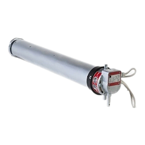
Simu T5E User manual

FR- Notice originale
5013732H
SIMU S.A.S. au capital de 5 000 000 €
Z.I. Les Giranaux - BP71 70103 Arc-Les-Gray CEDEX – FRANCE
RCS VESOUL B 425 650 090 SIRET 425 650 090 00011
n° T.V.A CEE FR 87 425 650 090
Installation
1
Réglage des ns de course
2
47
47 659 5 672 695
585 5 598 621
T
min. A
(mm) ØB
(mm) L1
(mm) L2
(mm)
A4xØB / 90
T5E
230V~50Hz
08/17 • 10/17 • 15/17
20/17 • 25/17 • 35/17 • 50/12
L1
L2
4
55
IP44
>>
1
OK
1
2
3
>>
2
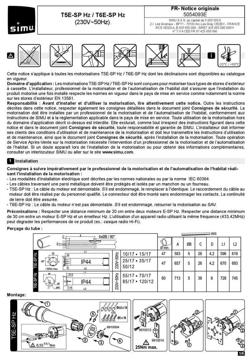
Perçage du tube :
Montage :
2.1. Connecter le moteur à l’interrupteur de réglage
(réf.: 2006024). Cet interrupteur est spécique aux moteurs
T5E / T5E-SP / T6E-SP
Ne l’utiliser en aucun cas avec un autre moteur !
2.2. Vérication du sens de rotation :
- Connecter l’interrupteur au secteur puis appuyer sur ▲ :
1- Si l’axe tourne dans le sens "montée", passer à l’étape 2.3
2- Si l’axe tourne dans le sens "descente", inverser les ls
marron (2) et noir (3) du moteur et refaire le test.
1/3
Durant les opérations de réglage des ns de course, le fonctionnement du moteur sera retardé de 1 seconde.
23
1
5
4
Ø4,8 x 10
Ø5 x 10
ACIER
25Nm max.
9910013
9910014
1
35Nm max.
T5E
(230V~50Hz)
-20°C / +60°C
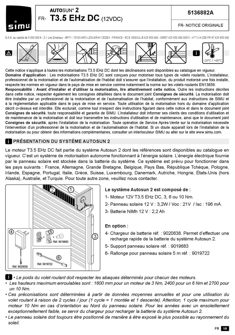
Cette notice s’applique à toutes les motorisations T5E dont les déclinaisons sont disponibles au catalogue en vigueur.
Domaine d’application : Les motorisations T5E sont conçues pour motoriser tous types de volets roulants. L’installateur, professionnel
de la motorisation et de l’automatisation de l’habitat doit s’assurer que l’installation du produit motorisé une fois installé respecte les
normes envigueur dans le pays demise en service comme notamment la norme sur les volets roulant EN13659.
Responsabilité : Avant d’installer et d’utiliser la motorisation, lire attentivement cette notice. Outre les instructions décrites dans
cette notice, respecter également les consignes détaillées dans le document joint Consignes de sécurité. La motorisation doit être
installée par un professionnel de la motorisation et de l’automatisation de l’habitat, conformément aux instructions de SIMU et à la régle-
mentation applicable dans le pays de mise en service. Toute utilisation de la motorisation hors du domaine d’application décrit ci-dessus
est interdite. Elle exclurait, comme tout irrespect des instructions gurant dans cette notice et dans le document joint Consignes de
sécurité, toute responsabilité et garantie de SIMU. L’installateur doit informer ses clients des conditions d’utilisation et de maintenance
de la motorisation et doit leur transmettre les instructions d’utilisation et de maintenance, ainsi que le document joint Consignes de
sécurité, après l’installation de la motorisation. Toute opération de Service Après-Vente sur la motorisation nécessite l'intervention d'un
professionnel de la motorisation et de l'automatisation de l'habitat. Si un doute apparaît lors de l'installation de la motorisation ou pour
obtenir des informations complémentaires, consulter un interlocuteur SIMU ou aller sur le site www.simu.com.
Consignes à suivre impérativement par le professionnel de la motorisation et de l’automatisation de l’habitat
réalisant l’installation de la motorisation :
- Les modalités d’installation électrique sont décrites par les normes nationales ou par la norme IEC 60364.
- Les câbles traversant une paroi métallique doivent être protégés et isolés par un manchon ou un fourreau.
- Le câble du moteur est démontable. S’il est endommagé, le remplacer à l’identique. Le raccordement du câble au moteur
doit être réalisé par du personnel qualié. Le connecteur doit être monté sans endommager les contacts. La continuité de
terre doit être assurée.
Bleu
Marron
Noir
Vert/jaune
PE
L
N
230V~50Hz
i

1
>>
0,5s
2
+
>>
≥3s
>>
6s max.
≥3s
>>
≥3s
>>
2.5 - Enregistrement du n de course bas :
L’utilisation de verrou (VAR, VAS, EASYLINK, OctoEasy) permet
le réglage automatique du n de course bas. Dans ce cas,
passer directement à l’étape 2.6. Si ce n’est pas le cas :
1- Positionner le moteur sur le point d’arrêt bas souhaité avec
les touches▲ et ▼
2- Pour mémoriser le n de course bas, faire 2 appuis successifs
sur la touche ▲:
- 1er appui d’une durée de 1/2s. sans obtenir de rotation du moteur.
- 2nd appui d’une durée supérieure à 3s. an d’obtenir une courte rotation du moteur dans un sens puis dans l’autre*.
Passer à l’étape 2.6.
2.3. Ouverture du mode réglage des ns de course :
- Appuyer simultanément sur ▲ et ▼ pendant 3 s. Le moteur effectue une courte rotation dans un
sens puis dans l’autre*. Passer à l’étape 2.4.
2.4. Initialisation de l’arrêt sur obstacle :
- Appuyer sur ▲ pendant 3 s. Le moteur effectue une courte rotation dans un sens puis dans
l’autre*. Passer à l’étape 2.5.
1
>>
0,5s
2
>>
≥3s
>>
6s max.
+
2.6. Enregistrement du n de course haut : L’utilisation de butée sur la lame nale permet le réglage automatique du n
de course haut en fonction du blocage fourni par les butées. Dans ce cas, passer directement à l’étape 2.7. Si ce n’est
pas le cas :
2- Pour mémoriser le n de course Haut, faire 2 appuis
successifs sur la touche ▼:
- 1er appui d’une durée de 1/2s. sans obtenir de rotation
du moteur.
- 2nd appui d’une durée supérieure à 3s. an d’ obtenir
une courte rotation du moteur dans un sens puis dans l’autre*.
Passer à l’étape 2.7.
≥3s
>>
2.7. Validation des réglages :
- Appuyer simultanément sur ▲ et ▼ pendant plus de 3 s. Le moteur effectue une courte rotation dans
un sens puis dans l’autre*. Après l’opération 2.7 les réglages sont terminés. Le fonctionnement du
moteur n’est plus retardé par rapport à la commande. Vous pouvez maintenant connecter le moteur sur
l’inverseur dénitif (§3).
* Maintenir l’appui jusqu’à ce que le moteur ait effectué une rotation dans les deux sens.
- Attention au sens de rotation des moteurs (§2.2).
- Utilisation obligatoire d’un inverseur interdisant d’actionner simultanément les touches ▲ et ▼.
- Possibilité de câbler 3 moteurs max. en parallèle sur un interrupteur.
- Longueur maxi. du câble entre le point de commande et le moteur : 50 mètres.
- Dans le cas d’une utilisation du moteur avec une commande type KNX / EIB, nous consulter.
- Attacher les câbles pour éviter tout contact avec une partie en mouvement.
- Si la motorisation est utilisée en extérieur, et si le câble d’alimentation est de type H05-VVF alors installer le câble dans un
conduit résistant aux UV, par exemple sous goulotte.
Câblage dénitif
3
Bleu
Marron
Noir
Vert/jaune
PE
L
NT5E
230V~50Hz
2/3
1- Positionner le moteur sur le point d’arrêt Haut souhaité
avec les touches▲ et ▼.

3
1
0,5s >3s
4
+
6s max.
2
>>
>> >> >> >> >>
4.1. Ré-ajustement du n de course bas : En cas de réglage automatique du n de course bas (utilisation de verrous),
le ré-ajustement sera effectué automatiquement tous les 60 cycles d’utilisation du produit.
Dans ce cas, ne pas effectuer les opérations ci-dessous.
1. Positionner le moteur sur le point d’arrêt bas réglé en §2.5 à l’aide de la touche ▼.
2. Effectuer 6 appuis successifs sur la touche ▼, d’une durée de 6 s chacun. A la n du 2ème, 3ème, 4ème, 5ème et du 6ème appui
le moteur effectue une courte rotation dans un sens puis dans l’autre*.
3. Positionner le moteur sur la nouvelle position basse souhaitée avec les touches ▲ et ▼.
4. Pour valider la nouvelle position n de course, effectuer 2 appuis successifs sur la touche ▲, le premier d’une durée de
0,5 s. et le seconde d’une durée de >3 s. A la n du second appui le moteur effectue une courte rotation dans un sens
puis dans l’autre*.
Ré-ajustement des ns de course
4
Annulation du réglage des ns de course
5
- Connecter le moteur à l’interrupteur de réglage (§2.1)
- Appuyer simultanément sur ▲ et ▼ pendant plus de 7 s. Le moteur effectue une courte rotation
dans un sens puis dans l’autre puis quelques secondes plus tard une deuxième rotation dans les
2 sens. Suite à cette opération, le moteur retourne dans sa conguration d’usine. Reprendre les
opérations au chapitre 2.
2s 7s
>7s
>> >>
3
1
0,5s >3s
4
+
6s max.
2
>>
>> >> >> >> >>
4.2. Ré-ajustement du n de course haut : En cas de réglage automatique du n de course haut (utilisation de butées),
le ré-ajustement sera effectué automatiquement tous les 60 cycles d’utilisation du produit.
Dans ce cas, ne pas effectuer les opérations ci-dessous.
1. Positionner le moteur sur le point d’arrêt haut réglé en §2.6 à l’aide de la touche ▲.
2. Effectuer 6 appuis successifs sur la touche ▲, d’une durée de 6 s. chacun. A la n du 2ème, 3ème, 4ème, 5ème et du 6ème appui
le moteur effectue une courte rotation dans un sens puis dans l’autre*.
3. Positionner le moteur sur la nouvelle position basse souhaitée avec les touches ▲ et ▼.
4. Pour valider la nouvelle position n de course, effectuer 2 appuis successifs sur la touche ▼, le premier d’une durée de
0,5 s. et le seconde d’une durée de >3 s. A la n du second appui le moteur effectue une courte rotation dans un sens
puis dans l’autre*.
Utilisation et maintenance
6
- Cette motorisation ne nécessite pas d’opération de maintenance.
- Appuyer sur la touche ▲du point de commande pour faire monter le produit motorisé.
- Appuyer sur la touche ▼ du point de commande pour faire descendre le produit motorisé.
Astuces et conseils d’utilisation :
Si le produit motorisé ne fonctionne toujours pas, contacter un professionnel de la motorisation et de l’automatisation de l’habitat.
3/3
Par la présente, SIMU SAS, F-70103 GRAY déclare en tant que fabricant que la motorisation couverte par ces instructions, marquée pour être alimentée en
230V~50Hz et utilisée comme indiqué dans ces instructions, est conforme aux exigences essentielles des Directives Européennes applicables et en particulier
de la Directive Machine 2006/42/EC et de la Directive CEM 2014/30/EU. Le texte complet de la déclaration de conformité à l'UE est disponible sur
www.simu.com. Emmanuel CARMIER, directeur général, GRAY, 11/2016.
CONSTATS
Le produit motorisé ne fonctionne pas
CAUSES POSSIBLES
La motorisation est en protection thermique
SOLUTIONS
Attendre que le moteur refroidisse

Adjustment of End limits
2
47
47 659 5 672 695
585 5 598 621
T
min. A
(mm) ØB
(mm) L1
(mm) L2
(mm)
A4xØB / 90
T5E
230V~50Hz
08/17 • 10/17 • 15/17
20/17 • 25/17 • 35/17 • 50/12
L1
L2
4
55
IP44
Blue
Brown
Black
Green/yellow
PE
L
N
230V~50Hz
>>
1
OK
1
2
3
>>
2
Drilling of the tube:
Assembly :
2.1. Connect the motor to the settings switch
(réf.: 2006024). This switch is specic to T5E / T5E-SP /
T6E-SP motors. Do not under any circumstances use
it with another motor!
2.2. Check the rotation direction:
- Connect the switch to the mains, then press ▲ :
1. If the tube turns in the "up" direction, go to step 2.3.
2. If the tube turns in the "down" direction, invert the Brown
(2) and Black (3) wires on the motor, and repeat the test.
During the End limits adjustment, there is a one-second delay in motor operation.
23
1
5
4
Ø4,8 x 10
Ø5 x 10
STEEL
25Nm max.
9910013
9910014
1
35Nm max.
Installation
1
-20°C / +60°C
These instructions apply to all T5E drive, the different versions of which are available in the current catalogue.
Field: T5E drive are designed to all types of roller shutters. The installer, who must be a motorisation and home automation professional,
must ensure that the drive product is installed in accordance with the standards in force in the country in which it is installed such as
EN 13659 relating to roller shutters.
Liability: Before installing and using the drive, please read operating and installation guide carefully. Please read these ins-
tructions carefully before installing and using the drive. In addition to following the instructions given in this guide, the instructions
detailed in the attached Safety instructions document must also be observed. The drive must be installed by a motorisation and home
automation professional, according to instructions from SIMU and the regulations applicable in the country in which it is commissioned.
It is prohibited to use the drive outside the eld of application described above. Such use, and any failure to comply with the instructions
given in this guide and in the attached Safety instructions document, absolves SIMU of any liability and invalidates the warranty. The
installer must inform its customers of the operating and maintenance conditions for the drive and must provide them with the instructions
for use and maintenance, and the attached Safety instructions document, after installing the drive. Any After-Sales Service operation
on the drive must be performed by a motorisation and home automation professional. If in doubt when installing the drive, or to obtain
additional information, contact a SIMU adviser or go to the website www.simu.com.
Instructions which must be followed by the drive and home automation professional installing the drive:
- Methods of wiring are given by national standards or IEC 60364 standard.
- Cables which pass through a metal wall must be protected and isolated using a sheath or sleeve.
- The cable for the motor can be removed. If it is damaged, replace by the same. The cable may only be connected to the
motor by qualied personnel. The connector is to be assembled without damaging the contacts. The continuity of the earth
connection must be ensured.
1/3
i
EN- Original instructions
5013732H
SIMU S.A.S. au capital de 5 000 000 €
Z.I. Les Giranaux - BP71 70103 Arc-Les-Gray CEDEX – FRANCE
RCS VESOUL B 425 650 090 SIRET 425 650 090 00011
n° T.V.A CEE FR 87 425 650 090
T5E
(230V~50Hz)

1
>>
0,5s
2
+
>>
≥3s
>>
6s max.
≥3s
>>
≥3s
>>
2.5. Adjustment of down end limit:
The use of rigid link (VAR, VAS, EASYLINK, OctoEasy) allows an
automatic adjustment of the Down end limit in accordance with the
blocking provided by the rigid link. If you use it, go directly to step
2.6, otherwise proceed to the following operations:
1. Position the motor on the desired down end limit using the ▲ and ▼ keys.
2. To memorize the down end limit, press ▲ twice, as folow:
2.3. Opening of the End limit switch setting mode:
- Press simultaneously on ▲ and ▼ for 3 seconds. The motor will run briey in one direction and
then in the in the other*. Go to step 2.4.
2.4. Initializing obstacle detection:
- Press on ▲ for 3 seconds. The motor will run briey in one direction and then in the other*. Go to
step 2.5.
- 1st press: for 0,5 second without the motor rotation.
- 2nd press: over 3 seconds, so the motor rotates briey one way, then the other*. Go to step 2.6.
1
>>
0,5s
2
>>
≥3s
>>
6s max.
+
2.6. Adjustment of up end limit:
The use of bottom slat stopper will allows an automatic adjustment of the up end limit in accordance with the blocking provi-
ded by the stopper. If you use it, go directly to step 2.7, otherwise proceed to the following operations:
1. Position the motor on the desired up end limit using the ▲ and
▼ keys.
2. To memorize the up end limit, press ▼ twice, as follow:
- 1st press for 0,5 second without the motor rotation.
- 2nd press over 3 seconds, so the motor rotates briey one way,
then the other*. Go to step 2.7.
≥3s
>>
2.7. Validation of end limits:
- Press the ▲ and ▼ keys simultaneously for at least 3 seconds. The motor will run briey in one
direction and then in the other*. The settings are now complete. There is not delay time any more.
You can now connect the motor to the nal switch (§3).
* Press the buttons until the motor turns into the two directions.
- Be careful of the direction of rotation (§2.2).
- Mandatory use of a reversing switch that stops the ▲ and ▼ keys being activated simultaneously.
- Possibility of wiring 3 motors max. in parallel on one switch.
- The length of the cable between the electrical switch and the motor must not exceed 50 m.
- Please do contact SIMU when using KNX / EIB electronic switching control devices.
- Attach cables to prevent any contact with moving parts. If the motor is used outdoors and if the power supply cable is of
the H05-VVF type, then run the cable in a UV-resistant conduit, e.g. trunking.
Final wiring
3
Blue
Brown
Black
Green/yellow
PE
L
NT5E
230V~50Hz
2/3

4.2. Re-adjustment of up end limit:
In case of an automatic adjustment (with buttom slat stopper) the re-adjustment will also be automatic (every 60 cycles).
In this case, do not proceed to the following operations.
1. Position the motor on the up end limit set in §2.6 using the ▲ key.
2. Press the ▲ key 6 times, each time for 6 seconds. After the 2nd, 3rd, 4th, 5th, and 6th press the motor rotates briey one way,
then the other*.
3. Position the motor on the new desired high position using the ▲ and ▼ keys.
4. To conrm the new End Limit position, press ▼ twice, once for 0,5 s without the motor rotation and the second time for at
least 3 seconds, so the motor rotates briey one way and then in the other*.
Cancelling the end limits adjustment
5
- Connect the motor to the settings switch (§2.1)
- Press the ▲ and ▼ keys simultaneously, for at least 7 seconds. The motor rotates
one way, then the other*, then a few seconds later rotates in both directions*.
After this operation, the motor returns to its factory settings; repeat the operations from
chapter 2.
2s 7s
>7s
>> >>
3
1
0,5s >3s
4
+
6s max.
2
>>
>> >> >> >> >>
3/3
Operation and maintenance
6
- This drive is maintenance-free.
- Press the ▲ button on the control point to raise the motorised product.
- Press the ▼ button on the control point to lower the motorised product.
Tips and recommendations for use:
If the motorised product still does not work, contact a drive and home automation professional.
SIMU SAS, F-70103 GRAY as manufacturer hereby declares that the drive covered by these instructions when marked for input voltage 230V~50Hz and used
as intended according to these instructions, is in compliance with the essential requirements of the applicable European Directives and in particular of the
Machinery Directive 2006/42/EC and EMC Directive 2014/30/EU. The full text of the EU declaration of conformity is available at www.simu.com.
Emmanuel CARMIER, general director, GRAY, 11/2016
PROBLEMS POSSIBLE CAUSES SOLUTIONS
The motorised product does not operate. The overheating protection on the drive has been activated. Wait for the drive to cool down.
4.1. Re-adjustment of down end limit:
In case of an automatic adjustment (with rigid link) the re-adjustment will also be automatic (every 60 cycles). In this case,
do not proceed to the following operations.
1. Position the motor on the down end limit set in §2.5 using the ▼ key.
2. Press the ▼ key 6 times, each time for 6 seconds. After the 2nd, 3rd, 4th, 5th, and 6th press the motor rotates briey one way,
then the other*.
3. Position the motor on the new desired lower position using the ▲ and ▼ keys.
4. To conrm the new End Limit position, press ▲ twice, once for 0,5 second without the motor rotating and the second time
for at least 3 seconds, so the motor rotates briey one way, then the other*.
Re-adjustment of end limits
4
3
1
0,5s >3s
4
+
6s max.
2
>>
>> >> >> >> >>

Installation
1
-20°C / +60°C
Diese Anleitung gilt für alle Antriebe vom T5E, deren Ausführungen im aktuellen Katalog zu nden sind.
Bestimmungsgemäße Verwendung: Die Antriebe T5E wurden für den Antrieb aller Arten von Rollläden. Der Installateur, ein Fach-
mann für Gebäudeautomation, muss sicherstellen, dass die Installation des Antriebs nach Montage den geltenden Vorschriften des
Orts der Inbetriebnahme entspricht. Hierzu gehören insbesondere die Norm: EN 13659 (Rollläden).
Haftung: Lesen Sie bitte vor der Montage und Verwendung des Antriebs diese Installationsanleitung sorgfältig durch.
Beachten Sie außer den Anweisungen in dieser Anleitung auch die detaillierten Hinweise im beiliegenden Dokument Sicherheit-
shinweise. Die Installation des Antriebs muss von einem Fachmann für Gebäudeautomation unter Einhaltung der Anweisungen
von SIMU und der am Ort der Inbetriebnahme geltenden Vorschriften ausgeführt werden. Jede Nutzung des Antriebs zu Zwecken,
die über den im vorliegenden Dokument beschriebenen Anwendungsbereich hinausgehen, ist untersagt. Jede Missachtung dieser
sowie aller anderen in dieser Anleitung und im beiliegenden Dokument Sicherheitshinweise enthaltenen Anweisungen führt zum
Ausschluss jeglicher Haftung und Gewährleistungsansprüche an SIMU. Der Installateur hat seine Kunden auf die Nutzungs- und
Wartungsbedingungen des Antriebs hinzuweisen und ihnen diese sowie das beiliegende Dokument Sicherheitshinweise nach
Abschluss der Installation des Antriebs auszuhändigen. Wartungs- und Reparaturarbeiten für den Antrieb dürfen ausschließlich von
Fachleuten für Gebäudeautomation ausgeführt werden. Für Fragen zur Installation des Antriebs und weiterführende Informationen
wenden Sie sich bitte an Ihren SIMU-Ansprechpartner oder besuchen Sie unsere Website www.simu.com.
Hinweise, die die installierende Fachkraft zu beachten hat:
- Die Verdrahtung muss internationalem oder dem IEC 60364 Standard entsprechen.
- Alle Kabel, die in Kontakt mit einer metallischen Wandung geraten könnten, müssen mit einer Hülse oder Ummantelung geschützt
und isoliert werden.
- Das Kabel des Antriebes kann demontiert werden : Wenn das Spannungsversorgungskabel beschädigt ist, muss es durch ein iden-
tisches Kabel ersetzt werden. Das Kabel muss vom qualizierten Personal an den Motor angeschlossen werden. Bei der Stecker-
montage dürfen die Kontakte nicht beschädigt werden. Die Durchgängigkeit des Schutzleiters muss sichergestellt sein.
Einstellen der Endlagen
2
47
47 6595672695
5855598621
T
min. A
(mm) ØB
(mm) L1
(mm) L2
(mm)
A4xØB / 90
T5E
230V~50Hz
08/17 • 10/17 • 15/17
20/17 • 25/17 • 35/17 • 50/12
L1
L2
4
55
48* IP44
Bohrungen in der Welle :
Montage :
23
1
5
4
Ø4,8 x 10
Ø5 x 10
STAHL
25Nm max.
9910013
9910014
1
35Nm max.
Blau
Braun
Schwarz
Grün/Gelb
PE
L
N
230V~50Hz230V~50Hz
>>
1
OK
1
2
3
>>
2
2.1. Verbinden Sie den Motor mit dem Einstellschalter
(Art.-Nr. :2006024). Dieser Schalter ist ausschließlich
für die Motoren T5E / T5E-SP / T6E-SP vorgesehen.
Verwenden Sie ihn in keinem Fall mit anderen
Motoren!
2.2. Überprüfen der Drehrichtung:
- Verbinden Sie den Schalter mit dem Stromnetz und drücken Auf:
1. Dreht sich die Achse "Aufwärts", gehen Sie zum Schritt 2.3. weiter.
2. Dreht sich die Achse "Abwärts" vertauschen Sie die Leitung Braun
(2) und Schwarz (3) und wiederholen den Test.
Während der Endlageneinstellung wird der Motorbetrieb um 1 Sekunde verzögert.
1/3
DE- Originalanleitung
5013732H
SIMU S.A.S. au capital de 5 000 000 €
Z.I. Les Giranaux - BP71 70103 Arc-Les-Gray CEDEX – FRANCE
RCS VESOUL B 425 650 090 SIRET 425 650 090 00011
n° T.V.A CEE FR 87 425 650 090
T5E
(230V~50Hz)
i

≥3s
>>
≥3s
>>
2.5. Einstellen der unteren Endlage:
Die Verwendung von feste Wellenverbinder (VAR, VAS, EASYLINK, OctoEasy) ermöglicht eine automatische Abschaltung
für den unteren Endpunkt. In diesem Fall Gehen Sie direkt weiter zu 2.6 Schritt , wenn es nicht der Fall ist:
1. Positionieren Sie den Motor mit den Tasten Auf und Ab auf
den gewünschten unteren Abschaltpunkt.
2. Zum Speichern der unteren Endlage drücken Sie die
Taste Auf 2 Mal hintereinander.
1. Druck: 0,5 Sek.lang ohne Motordrehung.
2. Druck: Länger als 3 Sek. mit kurzer Motordrehung in die eine,
dann in die andere Richtung*.Gehen Sie weiter zu Schritt 2.6.
2.3. Aktivieren des Endlagen-Einstellmodus:
- Drücken Sie gleichzeitig 3 Sek. lang Auf und Ab. Der Motor macht eine kurze Drehung in die
eine, dann in die andere Richtung*. Gehen Sie weiter zu Schritt 2.4.
2.4. Initialisieren der Sicherheitsabschaltung:
- Drücken Sie 3 Sek. lang Auf. Der Motor führt eine kurze Drehung in die eine, dann in die andere
Richtung aus*. Gehen Sie weiter zu Schritt 2.5.
1
>>
0,5s
2
>>
≥3s
>>
6s max.
+
2.6. Einstellen der oberen Endlage:
Die Verwendung von Stoppern an der Endschiene ermöglicht eine automatische Abschaltung für den oberen Endpunkt.
In diesem Fall Gehen Sie direkt weiter zu Schritt 2.7, wenn es nicht der Fall ist:
1. Positionieren Sie den Motor mit den Tasten Auf und Ab auf
den gewünschten oberen Abschaltpunkt.
2. Zum Speichern der oberen Endlage drücken Sie die Taste Ab
2 Mal hintereinander:
1. Druck: 0,5 Sek.lang ohne Motordrehung.
2. Druck: Länger als 3 Sek. mit kurzer Motordrehung in die eine,
dann in die andere Richtung*. Gehen Sie weiter zu Schritt 2.7.
≥3s
>>
2.7. Bestätigen der Einstellunge
n:
- Drücken Sie die Tasten Auf und Ab gleichzeitig über 3 Sek. lang. Der Motor führt eine kurze
Drehung in die eine, dann in die andere Richtung aus*. Nach Schritt 2.7 sind die Einstellungen
beendet. Der Motorbetrieb wird im Verhältnis zur Steuerung nicht mehr verzögert. Sie können den
Motor jetzt an den eigentlichen Schalter anschliessen (§3).
* Die Unterstützung aufrechterhalten, bis der Motor eine Umdrehung in den zwei Richtungen
durchgeführt hat.
- Vorsicht: Achten Sie auf die Drehrichtung (§2.2).
- Verwenden Sie unbedingt einen Schalter, bei dem das gleichzeitige Drücken der Tasten Auf und Ab nicht möglich ist.
- Es besteht die Möglichkeit, maximal 3 Motoren mit einem Schalter parallel zu verkabeln.
- Die länge der Zuleitung zwischen Shalter und Motor darf 50 Meter nicht überschreiten.
- Sollte der Motor durch ein KNX/EIB System gesteuert werden, wenden Sie sich bitte an uns, um die korrekte Funktion des
Motors zu gewährleisten.
- Bringen Sie die Kabel so an, dass sie nicht Kontakt zu beweglichen Teilen geraten können.
- Wenn der Antrieb im Freien montiert wird und mit einem Netzkabel vom Typ H05-VVF versehen ist, ist das Netzkabel vor
UV-Strahlen zu schützen, z.B. durch ein Schutzrohr.
Endgültiges Verkabeln
3
Blau
Braun
Schwarz
Grün/Gelb
PE
L
NT5E
230V~50Hz
2/3
1
>>
0,5s
2
+
>>
≥3s
>>
6s max.

4.1. Justieren der unteren Endlage:
Bei der vollautomatischen Endlageneinstellung (mit feste Wellenverbinder) erfolgt die Justierung der Endlagen automatisch
(alle 60 Zyklen). In diesem Fall die Operationen unten nicht durchführen.
1. Positionieren Sie den Motor auf den untere Abschaltpunkt, den Sie im Schritt §2.5 mit der Taste Ab geregelt haben.
2. Drücken Sie die Taste Ab 6 Mal hintereinander jeweils 6 Sek. lang. Nach dem 2ten, 3ten, 4ten, 5ten und 6ten Mal führt der
Motor eine kurze Drehung in die eine, dann in die andere Richtung aus*.
3. Positionieren Sie den Motor auf die neue gewünschte untere Lage mit den Tasten Auf und Ab.
4. Bestätigen Sie die neue Endposition, indem Sie die Taste Auf 2 Mal hintereinander drücken. 1. Druck: 0,5 Sek. lang ohne
Motordrehung, 2. Druck: Länger als 3 Sek. mit kurzer Motordrehung in die eine, dann in die andere Richtung*.
Neueinstellung der Endbegrenzung
4
3
1
0,5s >3s
4
+
6s max.
2
>>
>> >> >> >> >>
3/3
4.2. Justieren der oberen Endlage:
Bei der vollautomatischen Endlageneinstellung (mit Stoppern an der Endscheine) erfolgt die Justierung der Endlagen
automatisch (alle 60 Zyklen). In diesem Fall die Operationen unten nicht durchführen.
1. Positionieren Sie den Motor auf den obere Abschaltpunkt, den Sie im Schritt §2.6 mit der Taste Auf geregelt haben.
2. Drücken Sie die Taste Auf 6 Mal hintereinander jeweils 6 Sek. lang. Nach dem 2ten, 3ten, 4ten, 5ten und 6ten Mal führt der
Motor eine kurze Drehung in die eine, dann in die andere Richtung aus*.
3. Positionieren Sie den Motor auf die neue gewünschte obere Lage mit den Tasten Auf und Ab.
4. Bestätigen Sie die neue Endposition, indem Sie die Taste Ab 2 Mal hintereinander drücken. 1. Druck: 0,5 Sek. lang ohne
Motordrehung, 2. Druck: Länger als 3 Sek. mit kurzer Motordrehung in die eine, dann in die andere Richtung*.
- Verbinden Sie den Motor mit dem Einstellschalter (§2.1).
- Drücken Sie die Tasten Auf und Ab gleichzeitig über 7 Sekunden lang. Der Motor führt eine
kurze Drehung in die eine, dann in die andere Richtung aus und wenige Sekunden später
eine zweite Drehung in die 2 Richtungen*. Nach diesem Schritt kehrt der Motor in seine
werkseitig denierte Konguration zurück. Wiederholen Sie die Schritte des Abschnitts 2.
Rückgängigmachen der Endlageneinstellung
5
2s 7s
>7s
>> >>
3
1
0,5s >3s
4
+
6s max.
2
>>
>> >> >> >> >>
Anwendung und Wartung
6
- Für diesen Antrieb sind keine Wartungsarbeiten erforderlich:
- Ein einfacher Druck auf die Taste ▲ löst eine Öffnung des Behanges aus.
- Ein einfacher Druck auf die Taste ▼ löst eine Schliessung des Behanges aus.
Tipps und Empfehlungen die Installation:
Wenn das Produkt weiterhin nicht funktioniert, wenden Sie sich bitte an einen Fachmann für Gebäudeautomation.
SIMU SAS, F-70103 GRAY (Frankreich), erklärt hiermit als Hersteller, dass der in dieser Anleitung beschriebene Antrieb bei bestimmungsgemäßem Einsatz
und angeschlossen gemäß Kennzeichnung an eine 230V / 50Hz-Stromversorgung die grundlegenden Anforderungen der geltenden europäischen Richtlinien
und insbesondere der Maschinenrichtlinie 2006/42/EG sowie der EMV-Richtlinie 2014/30/EU erfüllt Der vollständige Text der EU-Konformitätserklärung ist
unter der Internetadresse www.simu.com verfügbar. Emmanuel CARMIER, Geschäftsführer, GRAY (Frankreich), 11/2016.
PROBLEME
Der angetriebene Behang funktionniert nicht
MÖGLICHE URSACHEN
Der Überhitzungsschutz des Antriebs wurde ausgelöst
LÖSUNGEN
Warten Sie, bis des Antrieb
abekühlt ist.

Instelling van de eindschakelaars
2
47
47 659 5 672 695
585 5 598 621
T
min. A
(mm) ØB
(mm) L1
(mm) L2
(mm)
A4xØB / 90
T5E
230V~50Hz
08/17 • 10/17 • 15/17
20/17 • 25/17 • 35/17 • 50/12
L1
L2
4
55
IP44
Blauw
Bruin
Zwart
Geel/groen
PE
L
N
230V~50Hz230V~50Hz
>>
1
OK
1
2
3
>>
2
Het Boren van de gaten:
Montage:
2.1. Sluit de motor aan op de schakelaar voor de instel-
ling (ref.: 2006024). Deze schakelaar is speciek voor
de motoren T5E / T5E-SP / T6E-SP. In geen geval
gebruiken met een andere motor!
2.2. Controle van de draairichting:
- Sluit de schakelaar op de stroom aan en druk op ▲ :
1. Als de as in de richting "omhoog" draait, doorgaan naar stap 2.3.
2. Als de as in de richting "omlaag" draait, de draden Bruin (2) en
Zwart (3) van de motor verwisselen en de test opnieuw uitvoeren.
Tijdens het instellen van de eindschakelaars wordt de werking van de motor 1 seconde vertraagd.
23
1
5
4
Ø4,8 x 10
Ø5 x 10
STAAL
25Nm max.
9910013
9910014
1
35Nm max.
Installation
1
-20°C / +60°C
Deze handleiding is geldig voor alle uitvoeringen van de motorisaties T5E die in de actuele catalogus zijn opgenomen.
Toepassingsgebied: De motorisaties T5E zijn ontworpen voor het motoriseren van elke typ rolluik. Het gemotoriseerde systeem moet
geïnstalleerd worden door een erkende installateur van automatiseringssystemen in woningen, in overeenstemming met de instructies
van SIMU en met de van het land van gebruik geldende normen en met name met de norm voor rolluiken EN13659.
Verantwoordelijkheid: Voordat de motorisatie geïnstalleerd en gebruikt wordt, moet deze handleiding zorgvuldig gelezen wor-
den. Houd u altijd aan de aanwijzingen die in deze handleiding staan. Houd u ook altijd aan de gedetailleerde voorschriften die in het
bijgevoegde document Veiligheidsvoorschriften staan. De motorisatie moet geïnstalleerd worden door een erkende installateur van
automatiseringssystemen in woningen, in overeenstemming met de instructies van SIMU en met de in het land van gebruik geldende
wet- en regelgeving. Ieder gebruik van de motorisatie buiten het hierboven beschreven toepassingsgebied is verboden. Hierdoor en
door het niet opvolgen van de instructies die in deze handleiding en in het bijgevoegde document Veiligheidsvoorschriften staan,
vervalt de aansprakelijkheid en de garantie van SIMU. De installateur moet de klant informeren over de voorwaarden voor het gebruik
en het onderhoud van de motorisatie en moet hem/haar, na de installatie van de motorisatie, de aanwijzingen voor het gebruik en het
onderhoud, evenals het bijgevoegde document Veiligheidsvoorschriften, overhandigen. Servicewerkzaamheden aan de motorisatie
mogen alleen uitgevoerd worden door een erkende installateur van automatiseringssystemen in woningen. Raadpleeg, bij twijfel tijdens
de installatie van de motorisatie of voor aanvullende informatie uw SIMU leverancier of ga naar de website www.simu.com.
Verplichte voorschriften voor de erkende installateur van automatiseringssystemen in woningen die de installatie van de
motorisatie uitvoert:
- Bedradingsvoorschriften worden voorgeschreven volgens de nationale normen of IEC 60364 normen.
- Kabels die door een metalen schot lopen moeten beschermd en geïsoleerd worden door een doorvoerrubber of.
- De kabel van de motor is afneembaar. Vervang hem door een identiek exemplaar als hij beschadigd raakt. De aansluiting van
de kabel van de motor moet worden uitgevoerd door gekwaliceerd personeel. De connector moet worden gemonteerd zonder de
contactpunten te beschadigen. De aardaansluiting moet worden verzekerd.
1/3
NL- Vertaling van de originele handleiding
5013732H
SIMU S.A.S. au capital de 5 000 000 €
Z.I. Les Giranaux - BP71 70103 Arc-Les-Gray CEDEX – FRANCE RCS
VESOUL B 425 650 090 SIRET 425 650 090 00011
n° T.V.A CEE FR 87 425 650 090
T5E
(230V~50Hz)
i

1
>>
0,5s
2
+
>>
≥3s
>>
6s max.
≥3s
>>
≥3s
>>
2.5. Instelling van de Eindschakelaar Beneden:
Door het gebruik van een vaste verbinding naar de lamellen
(VAR, VAS, EASYLINK, of OctoEasy) kan de motor de beneden
eindstand automatisch detecteren en instellen. In dit gaat geval
rechtstreeks naar 2.6, in ander geval:
1. Zet de motor op het gewenste eindpunt beneden met behulp
van de toetsen ▲ en ▼.
2. Om de Eindschakelaar beneden in het geheugen op te slaan
twee keer achter elkaar op de toets ▲ drukken:
2.3. Openen van de modus instelling van de eindschakelaars:
- Druk gedurende 3 sec. gelijktijdig op ▲ en ▼ . De motor draait kort in één richting en daarna in de
andere*. Ga door met stap 2.4.
2.4. Initialiseren van het stoppen voor een obstakel:
- Druk gedurende 3 seconden op ▲. De motor draait kort in één richting en daarna in de andere*.
Ga door met stap 2.5.
1e druk: met een duur van 0,5 s. Motor mag niet gaan draaien.
2e druk: met een duur langer dan 3 sec zodat de motor kort één kant op draait en dan de andere*. Ga door met stap 2.6.
2/3
1
>>
0,5s
2
>>
≥3s
>>
6s max.
+
2.6. Instelling van de Eindschakelaar bovenste:
Door het gebruik van een eindstop op de onderste lamel kan de motor de bovenste eindstand automatisch detecteren en
instellen. In dit gaat geval rechtstreeks naar 2.7, in ander geval:
1. Zet de motor op het gewenste eindpunt bovenste met behulp
van de toetsen ▲ en ▼.
2. Om de Eindschakelaar bovenste in het geheugen op te slaan
twee keer achter elkaar op de toets ▼ drukken:
1e druk: met een duur van 0,5 s (Motor mag niet gaan draaien).
2e druk: met een duur langer dan 3 sec zodat de motor kort één
kant op draait en dan de andere*. Ga door met stap 2.7.
≥3s
>>
2.7. Validatie van de instellingen:
- Druk gelijktijdig op de knoppen ▲ en ▼ gedurende meer dan 3 sec. De motor draait kort in één
richting en dan in de andere*. Na handeling 2.7 zijn de instellingen beëindigd. De werking van de
motor is niet meer 1 sec. vertraagd ten opzichte van de bediening. U kunt de motor nu aansluiten
op de schakelaar (§3).
* Druk op de knop totdat de motor kort in één richting draait en dan in de andere.
- Let op de draairichting (§2.2).
- Het is verplicht om een schakelaar te gebruiken waarbij het onmogelijk is om de toetsen ▲ en ▼ gelijktijdig in te drukken.
- Mogelijkheid om 3 parallelle max. motoren op een schakelaar te kabelen.
- De lengte van de kabel tussen de schakelaar en de motor mag nooit meer dan 50 m bedragen.
- Bij gebruik van de motor met een KNX / EIB controlepunt, gelieve ons te raadplegen.
- Kabels die door een metalen schot lopen moeten beschermd en geïsoleerd worden door een doorvoerrubber of huls.
Indien de motor buiten wordt gebruikt, moet de voedingskabel van het type H05-VVF in een tegen uv-licht bestendige koker
worden geïnstalleerd (bv. In een kabelgoot).
Denitieve bekabeling
3
Blauw
Bruin
Zwart
Geel/groen
PE
L
NT5E
230V~50Hz

4.2. Aanpassing van de eindschakelaar hoog:
Bij het gebruik van automatische instelling van de eindpodities (eindstop op onderste lamel) zal de her-instelling van beide eindposities
automatish plaatsvinden (iedere 60 cycli). In dit geval gaat u dus niet verder met de volgende acties.
1. Zet de motor op het eindpunt bovenste dat is ingesteld in §2.6 met behulp van de toets ▲.
2. Druk 6 keer achter elkaar op de toets ▲, telkens gedurende 6 sec. Na de 2de, 3de, 4de, 5de en 6de keer drukken draait de motor kort in één
richting en dan in de andere*.
3. Zet de motor op het nieuwe eindpunt bovenste met behulp van de toetsen ▲ en ▼.
4. Om de nieuwe positie te valideren drukt u 2 keer achter elkaar op de toets ▼, de eerste keer met een duur van 0,5 sec. (motor mag
niet gaan draaien) en de tweede keer met een duur van meer dan 3 sec, zodat de motor kort in één richting draait en dan in de andere*.
Annulering van de instelling van de eindschakelaars
5
3/3
- Sluit de motor aan op de schakelaar voor de instelling (§2.1)
- Druk gelijktijdig op de knoppen ▲ en ▼ gedurende meer dan 7 seconden. De motor
draait kort in één richting en dan in de andere* en dan na enkele seconden opnieuw in
de beide richtingen*. Na deze handeling staat de motor weer in de fabrieksinstellingen.
Begin de handelingen opnieuw bij hoofdstuk 2.
2s 7s
>7s
>> >>
3
1
0,5s >3s
4
+
6s max.
2
>>
>> >> >> >> >>
Gebruik en onderhoud
6
- Deze motorisatie heft geen onderhoud nodig.
- Door een druk op de toets ▲gaat het gemotoriseerde system omhoog.
- Door een druk op de toets ▼ gaat het gemotoriseerde system respectievelijk omlaag.
Tips en adviezen voor het gebruik:
Als het gemotoriseerd system nog steeds niet werkt, neem dan contact op met een erkende installateur van automatiseringssyste-
men in woningen.
Hierbij verklaart SIMU SAS, F-70103 GRAY dat de motorisatie die bestemd is om te worden gebruikt met 230V~50Hz volgens de aanwijzingen in dit document,
in overeenstemming is met de essentiële eisen en de andere relevante bepalingen van de Europese richtlijnen voor toepassing binnen de Europese Unie en in
het bijzonder met de Machinerichtlijn 2006/42/EG en de EMC-Richtlijn 2014/30/EU. De volledige EU-conformiteitsverklaring staat ter beschikking op de website
www.simu.com. Emmanuel CARMIER, directeur-generaal,GRAY, 11/2016.
PROBLEMEN
Het gemotoriseerde systeem werkt niet.
MOGELIJKE OORZAKEN
De thermische beveiliging van de motor is in werking gatreden.
OPLOSSINGEN
Wacht totdat de motor is afgekoeld
4.1. Her-instellen van de eindposities:
Bij het gebruik van automatische instelling van de eindpodities (vaste verbinding naar lamellen) zal de her-instelling van beide eindposities
automatish plaatsvinden (iedere 60 cycli). In dit geval gaat u dus niet verder met de volgende acties.
1. Zet de motor op het eindpunt beneden dat is ingesteld in §2.5 met behulp van de toets ▼.
2. Druk 6 keer achter elkaar op de toets ▼, telkens gedurende 6 sec. Na de 2de, 3de, 4de, 5de en 6de keer drukken draait de motor kort in één
richting en dan in de andere*.
3. Zet de motor op het nieuwe eindpunt beneden met behulp van de toetsen ▲ en ▼.
4. Om de nieuwe positie te valideren drukt u 2 keer achter elkaar op de toets ▲, de eerste keer met een duur van 0,5 sec. (motor mag
niet gaan draaien) en de tweede keer met een duur van meer dan 3 sec, zodat de motor kort in één richting draait en dan in de andere*.
Her-instellen van de eindposities
4
3
1
0,5s >3s
4
+
6s max.
2
>>
>> >> >> >> >>

Instalación
1
-20°C / +60°C
Este manual se aplica a todos los motores T5E cuyas versiones se encuentran disponibles en el catálogo en vigor.
Ámbito de aplicación: Los motores T5E están diseñados para automatizar todos los tipos de persianas enrollables. El instalador,
profesional del motor y de la automatización de la vivienda, debe asegurarse de que la instalación del producto automatizado una vez
instalado respete las normas vigentes en el país donde vaya a utilizarse y las normas sobre persianas enrollables EN 13659.
Responsabilidad: Antes de instalar y utilizar a motorización, lea atentamente este manual. Además de las instrucciones descritas
en este manual, deben respetarse las normas detalladas en el documento adjunto Normas de seguridad. La motorización debe ser
instalada por un profesional de la motorización y de la automatización de la vivienda, de conformidad con las instrucciones propor-
cionadas por SIMU y con la normativa aplicable en el país donde vaya a utilizarse. Se prohíbe cualquier uso de la motorización fuera
del ámbito de aplicación anteriormente descrito. Ello conllevaría, como todo incumplimiento de las instrucciones que guran en este
manual y en el documento adjunto Normas de seguridad, la exclusión de toda responsabilidad por parte de SIMU y la anulación de la
garantía. El instalador debe informar a sus clientes de las condiciones de uso y de mantenimiento de la motorización y debe entregarles
las instrucciones de uso y de mantenimiento, así como el documento adjunto Normas de seguridad, tras la instalación de la motori-
zación. Cualquier operación del Servicio posventa que deba realizarse en la motorización requiere la intervención de un profesional
de la motorización y la automatización de la vivienda. Para resolver cualquier duda que pudiera surgir durante la instalación del motor
o para obtener información adicional, póngase en contacto con uno de los agentes de SIMU o visite la página web www.simu.com.
Instrucciones que debe seguir obligatoriamente el profesional de la motorización y la automatización del hogar que efectúe
la instalación de la motorización:
- Las modalidades de instalación eléctrica se describen en las normas nacionales o en la norma IEC 60364.
- En caso de que los cables deban atravesar una pared metálica, deben protegerse y aislarse con un manguito o una vaina.
- El cable de la motorización es desmontable. Si está deteriorado, sustitúyalo por otro idéntico. Sólo Personal calicado podrá efectuar
la conexión del cable al motor. El conector deberá montarse sin dañar los contactos. Se deberá garantizar la continuidad de tierra.
Ajuste de los nales de carrera
2
47
47 659 5 672 695
585 5 598 621
T
min. A
(mm) ØB
(mm) L1
(mm) L2
(mm)
A4xØB / 90
T5E
230V~50Hz
08/17 • 10/17 • 15/17
20/17 • 25/17 • 35/17 • 50/12
L1
L2
4
55
IP44
Azul
Marrón
Negro
Verde/amarillo
PE
L
N
230V~50Hz
230V~50Hz
>>
1
OK
1
2
3
>>
2
Perforación del tubo:
Montaje:
2.1. Conectar el motor al interruptor de maniobra
(ref.: 2006024). Este interruptor es especíco para
los motores T5E / T5E-SP / T6E-SP. No utilizarlo en
ningún caso con otro motor!
2.2. Comprobación del sentido de rotación:
- Conectar el interruptor a la red eléctrica y luego pulsar en ▲:
1- Si el eje gira en el sentido de "subida", pasar a la etapa 2.3.
2- Si el eje gira en el sentido de "bajada", invertir los hilos Marrón
(2) y negro (3) del motor, y reanudar el test.
Durante las operaciones de ajuste de los nales de carrera, el funcionamiento del motor tendrá un retraso de 1 segundo.
23
1
5
4
Ø4,8 x 10
Ø5 x 10
ACERO
25Nm max.
9910013
9910014
1
35Nm max.
1/3
ES- Traducción del manual original
5013732H
SIMU S.A.S. au capital de 5 000 000 €
Z.I. Les Giranaux - BP71 70103 Arc-Les-Gray CEDEX – FRANCE
RCS VESOUL B 425 650 090 SIRET 425 650 090 00011
n° T.V.A CEE FR 87 425 650 090
T5E
(230V~50Hz)
i

1
>>
0,5s
2
+
>>
≥3s
>>
6s max.
≥3s
>>
≥3s
>>
2.5. Ajuste del Final de carrera bajada:
La utilizacion de los tirantes de bloqueo (VAR, VAS, EASYLINK,
OctoEasy) permite al motor de regular automaticamente el Final
de carrera de Bajada. En este caso, pasar directamente a las
instrucciones 2.6, si no fuera el caso:
1. Colocar el motor en el punto de parada bajada deseado por
medio de las teclas ▲ y ▼.
2. Para memorizar el n de recorrido bajo, presionar 2 veces
sucesivamente la tecla ▲:
2.3. Abertura del modo ajuste de los nes de recorrido:
- Pulsar simultáneamente en ▲ y ▼ durante 3 seg. El motor efectúa una corta rotación en un
sentido y luego en el otro*. Pasar a la etapa 2.4.
2.4. Inicialización de la parada por obstáculo:
- Pulsar en ▲ durante 3 segundos. El motor efectúa una corta rotación en un sentido y luego en el
otro*. Pasar a la etapa 2.5.
1a impulsión: de una duración de 0,5sg sin obtener rotación del motor.
2a impulsión: de una duración superior a 3 seg, con objeto de obtener una corta rotación del motor en un sentido y luego en
el otro*. Pasar a la etapa 2.6.
2/3
1
>>
0,5s
2
>>
≥3s
>>
6s max.
+
2.6. Ajuste del Final de carrera subida:
La utilizacion de topes sobre la lama terminal permite al motor de regular automaticamente el Final de Carrera de Subida,
en funccion del bloqueo ofrecido por los topes. En este cado pasar directamente a las instrucciones 2.7, si no fuera el caso:
1. Colocar el motor en el punto de parada subida deseado por
medio de las teclas ▲ y ▼.
2. Para memorizar el n de recorrido bajo, presionar 2 veces
sucesivamente la tecla ▼:
1a impulsión: de una duración de 0,5 sg sin obtener rotación del
motor.
2a impulsión: de una duración superior a 3 seg, con objeto de
obtener una corta rotación del motor en un sentido y luego en el
otro*. Pasar a la etapa 2.7.
≥3s
>>
2.7. Validación de los ajustes:
- Presionar simultáneamente las teclas ▲ y ▼ durante más de 3 seg. El motor efectúa una corta
rotación en un sentido y luego en el otro*. Tras la operación 2.7, los ajustes están programado.
El funcionamiento del motor no será retrasado con respecto a la maniobra. Se puede conectar
ahora el motor al inversor denitivo (§3).
* Mantener la impulsion del inverseur hasta que el motor haya efectuado una rotación en los
dos sentidos.
- Atención al sentido de rotación (§2.2).
- Utilización obligatoria del inversor, bloqueando la acción simultánea en las teclas ▲ y ▼.
- Posibilidad de cablear 3 motores como máximo en paralelo en un interruptor.
- La longitud del cable entre el motor y el punto de mando no debe exceder de 50 m.
- Cuando se utilice el motor con un control KNX / EIB, por favor consúltenos.
- Fije los cables para evitar cualquier contacto con un componente en movimiento.
- Si el motor esta a la intemperie y el cable de alimentación es de tipo H05-VVF, instale el cable en un conducto resistente a
los rayos UV, como una canaleta.
Cableado denitivo
3
Azul
Marrón
Negro
Verde/amarillo
PE
L
NT5E
230V~50Hz

4.1. Reajuste del Final de carrera bajada:
En caso de regulación automatica del nal de carrera de Bajada gracias a la utilización de los tirantes de bloqueo, el reajuste sera efec-
tuado automaticamente todos los 60 ciclos de utilizacion del motor. En este caso, no efectuar las operaciones mencionadas debajo.
4.2. Reajuste del Final de carrera subida:
En caso de regulación automatica del nal de carrera de Subida, gracias a la utilización de topes, el reajuste sera efectuado automatica-
mente todos los 60 ciclos de utilización del motor. En este caso, no efectuar las operaciones mencionadas debajo.
1. Posicionar el motor sobre el punto de parada de bajada regulado en §2.5 con la ayuda de la tecla ▼.
2. Efectuar 6 impulsiones sucesivas en la tecla ▼, de una duración de 6 seg cada vez. Después de las 2, 3, 4, 5 y 6 impulsión el motor
efectúa una corta rotación en un sentido y luego en el otro*.
3. Poner el motor en la nueva posición de bajada deseada por medio de las teclas ▲ y ▼.
4. Para validar la nueva posición Fin de carrera : efectuar 2 impulsiones sucesivas en la tecla ▲ ,la primera de una duración de 0,5 seg
sin obtener la rotación del motor, y la segunda de una duración superior a 3 seg, con objeto de obtener una corta rotación del motor en
un sentido y luego en el otro*.
1. Poner el motor en el punto de parada subida ajustado en §2.6 por medio de la tecla ▲.
2. Efectuar 6 impulsiones sucesivas en la tecla ▲, de una duración de 6 seg cada vez. Después de las 2, 3, 4, 5 y 6 impulsión el motor
efectúa una corta rotación en un sentido y luego en el otro*.
3. Poner el motor en la nueva posición de subida deseada por medio de las teclas ▲ y ▼.
4. Para validar la nueva posición Fin de carrera: efectuar 2 impulsiones sucesivas en la tecla ▼,la primera de una duración de 0,5 seg sin
obtener la rotación del motor, y la segunda de una duración superior a 3 seg, con objeto de obtener una corta rotación del motor en un
sentido y luego en el otro*.
Reajuste del nale de carrera
4
Anulación del ajuste de los nales de carrera
5
- Conectar el motor al interruptor de ajuste (§2.1)
- Presionar simultáneamente las teclas ▲ y ▼, durante más de 7 segundos. El motor
efectúa una corta rotación en un sentido y luego en el otro, y unos segundos más tarde
una segunda rotación en ambos sentidos*. Tras esta operación, el motor vuelve a su
conguración de base. Reanudar las operaciones a partir del capítulo 2.
2s 7s
>7s
>> >>
3
3
1
1
0,5s >3s
4
+
6s max.
0,5s >3s
4
+
6s max.
2
>>
>> >> >> >> >>
2
>>
>> >> >> >> >>
Uso y Mantenimiento
6
- Este mecanismo no requiere ninguna operación de mantenimiento.
- Al pulsar una vez el botón ▲, el producto automatizado sube por completo
- Al pulsar una vez el botón ▼ el producto automatizado baja por completo.
Trucos y consejos de uso:
Si el producto automatizado sigue sin funcionar, póngase en contacto con un profesional de la motorización y la automatización de
la vivienda.
3/3
En virtud del presente documento, SIMU SAS, F-70103 GRAY declara que, en tanto que fabricante de la motorización que cubren estas instrucciones, mar-
cada para recibir alimentacióna 230V~50Hz y utilizada tal y como se indica en las mismas, es conforme a las exigencias básicas de las Directivas europeas
aplicables y, en particular, la Directiva de máquinas 2006/42/CE y la Directiva de CEM 2014/30/UE. El texto completo de la declaración de conformidad en la
UE se encuentra disponible en www.simu.com. Emmanuel CARMIER, director general, GRAY, 11/2016.
PROBLEMAS
El producto automatizado no funciona
POSIBLES CAUSAS
La motorizaci
ón esta en térmico.
SOLUCIONES
Espere a que la motorizaci
ó
n se enfrie.

Regulação do m de curso
2
47
47 659 5 672 695
585 5 598 621
T
min. A
(mm) ØB
(mm) L1
(mm) L2
(mm)
A4xØB / 90
T5E
230V~50Hz
08/17 • 10/17 • 15/17
20/17 • 25/17 • 35/17 • 50/12
L1
L2
4
55
IP44
Azul
Castanho
Preto
Amarelo/verde
230V~50Hz
PE
L
N
>>
1
OK
1
2
3
>>
2
Furação do tubo:
Montagem:
2.1. Ligar o motor ao interruptor de Regulação
(réf.: 2006024). Este interruptor é espécífíco para os
motores T5E / T5E-SP / T6E-SP Não deve ser utilizado
com outro tipo de motor!
2.2. Vericação do sentido de rotação:
- Ligar o interruptor a rede eléctrica, em seguida pressionar a tecla ▲:
1- Se o eixo rodar no sentido da "subida", passar para a etapa 2.3.
2- Se o eixo rodar no sentido da "bajada", inverter os os
Castanho(2) e Preto(3) do motor, e voltar a fazer o teste.
Durante a regulação de m de curso, o funcionamento do motor será retardado de 1 segundo
23
1
5
4
Ø4,8 x 10
Ø5 x 10
AÇO
25Nm max.
9910013
9910014
1
35Nm max.
Instalação
1
-20°C / +60°C
Estas instruções aplicam-se a todos os motores T5E, cujas variantes estão disponíveis no catálogo em vigor.
Área de aplicação: Os motores Typ T5E foram concebidos para motorizar todos os tipos de estores. O técnico de instalação, pro
ssional da motorização e da automatização do lar, deve assegurar que a instalação do produto motorizado respeita as normas em vigor
no país de colocação em serviço, tais como a norma sobre os estores EN13659.
Responsabilidade: Antes de instalar e de utilizar o motor, ler atentamente estas instruções. Tal como acontece com as instru-
ções descritas nestas instruções, também devem ser respeitadas as instruções detalhadas apresentadas no documento em anexo
Instruções de segurança. O motor deve ser instalado por um prossional da motorização e da automatização do lar, em conformidade
com as instruções da SIMU e a regulamentação do país no qual é instalado. Qualquer utilização do motor fora da área de aplicação
acima descrita é proibida. Tal utilização excluiria, como qualquer desrespeito pelas instruções constantes deste guia e no documento
em anexo Instruções de segurança, toda a responsabilidade e garantia da SIMU. O técnico de instalação deve informar os seus
clientes sobre as condições de funcionamento e de manutenção do motor e deve comunicar-lhes as instruções de utilização e de
manutenção, bem como o documento em anexo Instruções de segurança, após a instalação do motor. Todas as operações do Ser-
viço Pós-Venda no motor requerem a intervenção de um prossional da motorização e da automatização do lar. Em caso de dúvidas
aquando da instalação do motor ou para obter informações complementares, consultar um interlocutor SIMU ou o site www.simu.com.
Instrucciones que debe seguir obligatoriamente el profesional de la motorización y la automatización del hogar que efectúe
la instalación de la motorización:
- Las modalidades de instalación eléctrica se describen en las normas nacionales o en la norma IEC 60364.
- En caso de que los cables deban atravesar una pared metálica, deben protegerse y aislarse con un manguito o una vaina.
- El cable de la motorización es desmontable. Si está deteriorado, sustitúyalo por otro idéntico. Sólo Personal calicado podrá
efectuar la conexión del cable al motor. El conector deberá montarse sin dañar los contactos. Se deberá garantizar la continuidad de
tierra.
1/3
PT- Tradução do manual original
5013732H
SIMU S.A.S. au capital de 5 000 000 €
Z.I. Les Giranaux - BP71 70103 Arc-Les-Gray CEDEX – FRANCE
RCS VESOUL B 425 650 090 SIRET 425 650 090 00011
n° T.V.A CEE FR 87 425 650 090
T5E
(230V~50Hz)
i

1
>>
0,5s
2
+
>>
≥3s
>>
6s max.
≥3s
>>
≥3s
>>
2.5. Ajuste do m de curso inferior:
A utilização de uma ligação rígida (VAR, VAS, EASYLINK, OctoEasy) permite um ajuste automático do m de curso inferior
em conformidade com o sistema de bloqueio da ligação. Se utilizar esta ligação, siga para o ponto 2.6, caso contrário,
proceda de acordo com o seguinte:
1. Posicionar o motor no ponto de paragem inferior desejado
servindo-se das teclas ▲ e ▼.
2. Para memorizar o m de curso inferior, pressionar 2 vezes
a tecla ▲:
2.3. Abertura da programação do m de curso :
- Pressionar simultaneamente nas teclas ▲ e ▼ durante 3 segundos. O motor efectua uma curta
rotação em ambos os sentidos*. Passar para a etapa 2.4.
2.4. Inicialização da paragem face a obstáculo :
- Pressionar na tecla ▲ durante 3 segundos. O motor efectua uma curta rotação num sentido e de
seguida em sentido oposto*. Passar para a etapa 2.5.
- Pressionnar durante 0,5 segundo sem provocar rotação
do motor.
- Pressionnar durante 3 segundos, a m de provocar uma curta
rotação do motor num sentido e depois no sentido oposto*. Passar para a etapa 2.6.
2/3
1
>>
0,5s
2
>>
≥3s
>>
6s max.
+
2.6. Ajuste do m de curso superior:
Com a utilização de batentes na base do estore, o m de curso superior é ajustado automaticamente. Neste caso, passar
directamente ao ponto 2.7, caso contrário proceda de acordo com o seguinte:
1. Posicionar o motor no ponto de paragem superior desejado
servindo-se das teclas ▲ e ▼.
2. Para memorizar o m de curso superior, pressionar 2 vezes
a tecla ▼:
- Pressionnar durante 0,5 segundo sem provocar rotação do
motor.
- Pressionnar durante 3 segundos, a m de provocar uma curta
rotação do motor num sentido e depois no sentido oposto*.
Passar para a etapa 2.6.
≥3s
>>
2.7. Validação do programação :
- Pressionar simultaneamente nas teclas e mais de 3 seg. O motor efectua uma curta rotação em
ambos sentidos*. Após a operação 2.7 os ajustes estão terminados. O funcionamento do motor
deixou de estar retardado em relação ao comando. Agora já pode conectar o motor ao inversor
denitivo (§3).
* Pressione as teclas até que o motor rode em ambos os sentidos.
- Vericar ao sentido de rotação (§2.2).
- Utilização obrigatória de um inversor que impeça de activar simultaneamente as teclas ▲ e ▼.
- Possibilidade de ligar 3 motores máximos em paralelo sobre um interruptor.
- Prender os cabos para evitar um eventual contacto com uma parte móvel.
- O comprimento do cabo entre o motor e o ponto de comando não deve exceder os 50 M.
- Quando utilizar um motor com controlo KNX / EIB, por favor contacte-nos.
- Se o motor for utilizado no exterior e o cabo de alimentação for do tipo H05-VVF, instale o cabo numa conduta resistente
aos UV, por exemplo, debaixo de caleiras O cabo do motor não pode ser desmontado.
Ligação denitiva
3
Azul
Castanho
Preto
Amarelo/verde
PE
L
NT5E
230V~50Hz

4.2 - Reajuste m de curso superior :
No caso de um ajuste automático (com a tecla de paragem da lâmina), o reajuste também será automático (em casa 60 ciclos). Neste
caso, não siga as seguintes instruções:
1. Posicionar o motor no ponto de paragem superior ajustado em §2.6 por meio da tecla ▲.
2. Efectuar 6 pressões sucessivas na tecla ▲, de uma duração de 6 segundos cada uma. Depois de 2, 3, 4, 5 e 6 Pressione o motor
efectua uma curta rotação num sentido e depois no sentido oposto*.
3. Posicionar o motor numa nova posição superior pretendida servindo-se das teclas ▲ e ▼.
4. Para validar a nova posição do interruptor de m de curso: pressionar 2 vezes na tecla ▼, a primeira de uma duração de 0,5 seg.
sem provocar rotação do motor, e a segunda de uma duração superior a 3 seg., a m de provocar uma curta rotação em ambos os
sentidos*.
Anulação do programação
5
- Ligar o motor ao interruptor de ajuste (§2.1)
- Pressionar simultaneamente nas teclas ▲ e ▼,durante pelo menos 7 segundos. O
motor efectua uma curta rotação em ambos os sentidos*, passados alguns segundos, o
motor volta a efectuar uma curta rotação em ambos os sentidos*. Após esta operação,
o motor volta à sua conguração inicial; retomar as operações a partir do capítulo 2.
2s 7s
>7s
>> >>
3
1
0,5s >3s
4
+
6s max.
2
>>
>> >> >> >> >>
Utilização e manutenção
6
- Este motor não necessita de manutenção.
- Pressionar o botão ▲ do ponto de comando, para fazer subir op roduto electricado.
- Pressionar o botão ▼ do ponto de comando, para fazer descer o produto electricado.
Sugestões e conselhos de utilização:
Se o produto electricado continuar a não funcionar ,contactar um prossional da motorização e da automatização do lar.
3/3
En virtud del presente documento, SIMU SAS, F-70103 GRAY declara que, en tanto que fabricante de la motorización que cubren estas instrucciones, mar-
cada para recibir alimentacióna 230V~50Hz y utilizada tal y como se indica en las mismas, es conforme a las exigencias básicas de las Directivas europeas
aplicables y, en particular, la Directiva de máquinas 2006/42/CE y la Directiva de CEM 2014/30/UE. El texto completo de la declaración de conformidad en la
UE se encuentra disponible en www.simu.com. Emmanuel CARMIER, director general, GRAY, 11//2016.
PROBLEMAS CAUSAS POSSÍVEIS SOLUÇÕES
O produto electricado não funciona. A motorização está quente. Aguardar até que a motorização arrefeça.
4.1- Reajuste m de curso inferior :
No caso de um ajuste automático (utilização de uma ligação rígida), o reajuste também será automático (em cada 60 ciclos). Neste caso,
não siga as seguintes instruções.
1. Posicionar o motor no ponto de paragem inferior ajustado em §2.5 por meio da tecla ▼.
2. Efectuar 6 pressões sucessivas na tecla ▼, de uma duração de 6 segundos cada uma. Depois de 2, 3, 4, 5 e 6 pressione o motor
efectua uma curta rotação num sentido e depois no sentido oposto*.
3. Posicionar o motor numa nova posição inferior pretendida servindo-se das teclas ▲ e ▼.
4. Para validar a nova posição do interruptor de m de curso : pressionar 2 vezes na tecla ▲, a primeira de uma duração de 0,5 seg.
sem provocar rotação do motor, e a segunda de uma duração superior a 3 seg., a m de provocar uma curta rotação em ambos os
sentidos*.
Reajuste dos ns de curso
4
3
1
0,5s >3s
4
+
6s max.
2
>>
>> >> >> >> >>

Instalacja
1
-20°C / +60°C
Ta instrukcja dotyczy wszystkich napędów Typ T5E, których różne wersje są dostępne w aktualnym katalogu.
Zakres stosowania: Napędy T5E są przeznaczone do napędzania wszystkich rodzajów rolet. Instalator, będący specjalistą w z zakresu
urządzeń mechanicznych i automatyki w budynkach mieszkalnych, powinien upewnić się, czy instalacja napędzanego produktu została
wykonana zgodnie z normami obowiązującymi w kraju użytkowania produktu, a w szczegolności z normą dotyczącą rolet EN13659.
Odpowiedzialność: Przed zamontowaniem i użytkowaniem napędu, należy uważnie przeczytać niniejszą instrukcję. Poza
wskazówkami podanymi w tej instrukcji, konieczne jest również przestrzeganie zaleceń przedstawionych w załączonym dokumencie
Zasady bezpieczeństwa. Napęd powinien być montowany przez specjalistę z zakresu urządzeń mechanicznych i automatyki w budyn-
kach mieszkalnych, zgodnie z instrukcjami SIMU oraz zasadami obowiązującymi w kraju użytkowania produktu. Użytkowanie napędu
poza zakresem stosowania opisanym powyżej jest zabronione. Spowodowałoby ono, podobnie jak nieprzestrzeganie wskazówek
zawartych w niniejszej instrukcji oraz w załączniku Zasady bezpieczeństwa, zwolnienie producenta z wszelkiej odpowiedzialności
oraz utratę gwarancji SIMU. Po zakończeniu montażu napędu, instalator powinien poinformować klientów o warunkach użytkowania
i konserwacji napędu i przekazać im instrukcje dotyczące jego użytkowania i konserwacji, jak również załączony dokument Zasady
bezpieczeństwa. Wszelkie czynności z zakresu obsługi posprzedażowej napędu muszą być wykonywane przez specjalistę z zakresu
urządzeń mechanicznych i automatyki w budynkach mieszkalnych. W przypadku pojawienia się wątpliwości podczas montażu napędu
lub w celu uzyskania dodatkowych informacji, należy skonsultować się z przedstawicielem SIMU lub odwiedzić stronę internetową
www.simu.com.
Zalecenia, które muszą być stosowane przez specjalistę z zakresu napędów i automatyki w budynkach mieszkalnych,
wykonującego instalację napędu:
- Sposoby okablowania są określone w normach krajowych oraz w normie europejskiej IEC 60364.
- W przypadku wykonywania instalacji elektrycznych przez ściany, przewody muszą być zabezpieczone i odizolowane przez prze-
pusty kablowe i/ lub rurki osłonowe.
- Przewodu da się zdemontować, Uszkodzony przewód zasilający należy wymienić na taki sam. Przewód zasilający może być
podłączany do napędu wyłącznie przez wykwali kowany personnel. Złącze należy zamontować bez uszkadzania styków. Należy
zapewnić ciągłość uziemienia.
47
47 659 5 672 695
585 5 598 621
T
min. A
(mm) ØB
(mm) L1
(mm) L2
(mm)
A4xØB / 90
T5E
230V~50Hz
08/17 • 10/17 • 15/17
20/17 • 25/17 • 35/17 • 50/12
L1
L2
4
55
IP44
Wykonywanie otworów w
rurze nawojowej:
Montaż:
23
1
5
4
Ø4,8 x 10
Ø5 x 10
STAL
25Nm max.
9910013
9910014
1
35Nm max.
Regulacja położeń krańcowych
2
Niebieski
Bràzowy
Czarny
Zielono/żółty
PE
L
N
230V~50Hz
230V~50Hz
>>
1
OK
1
2
3
>>
2
2.1. Połączyć napęd z przełącznikiem regulacyjnym
(nr fabr.:2006024). Ten przełącznik jest wykonany specjalnie
dla napędów
T5E / T5E-SP / T6E-SP
. W żadnym wypadku
nie wolno stosować go do innych napędów!
2.2. Sprawdzenie kierunku obrotów:
- Podłączyć zazilanie do przełącznika, a następnie nacisnąć na przycisk ▲:
1. Jeżeli rura nawojowa obraca się w kierunku "Góra" należy przejść
do pkt. 2.3.
2. Jeżeli rura nawojowa obraca się w kierunku "Doł", zamienić przewody
brązowy(2) i czarny(3) napędu, a następnie ponowić próbę.
Podczas wykonywania regulacji położeń krańcowych działanie napędu będzie opóźnione o 1 sekundę.
1/3
PL- Tłumaczenie instrukcji oryginalnej
5013732H
SIMU S.A.S. au capital de 5 000 000 €
Z.I. Les Giranaux - BP71 70103 Arc-Les-Gray CEDEX – FRANCE RCS
VESOUL B 425 650 090 SIRET 425 650 090 00011
n° T.V.A CEE FR 87 425 650 090
T5E
(230V~50Hz)
i

1
>>
0,5s
2
>>
≥3s
>>
6s max.
+
2.6. Regulacja górnego położenia krańcowego:
Zastosowanie odbojników w listwie dolnej pozwala na automatyczną regulację górnego wyłącznika krańcowego. Zapewniają one odpowiednie blokowanie.
Jeżeli są stosowane, należy bezpośrednio przejść do etapu 2.7. W przeciwnym przypadku należy postępować zgodnie z poniższą procedurą:
1. Ustawić napęd w żądanym górnym położeniu krańcowym stosując przyciskow ▲ i ▼.
2. W celu apisania w pamięci ustawienia górnego położenia krańcowego, należy
nacisnąć 2- krotnie na przycisk ▼:
- Pierwszy raz naciskać przez 0,5 s bez obrotów napędu.
- Drugi raz naciskać ponad 3 sekundy tak, aby napęd wykonał krótki obrót w
jednym kierunku, a następnie w drugim*.Należy przejść do punktu 2.7.
≥3s
>>
2.7. Zatwierdzenie regulacji:
- Naciskać równocześnie na przyciski ▲ i ▼ przez okres ponad 3 sek. Napęd wykonuje krótki obrót w jednym
kierunku, a następnie w drugim*. Po wykonaniu czynności 2.7 regulacje są zakończone. Działanie napędu nie
jest już opóźnione w stosunku do polecenia. Można teraz połączyć napęd z przełącznikiem do pracy (§3).
* Naciskać na przyciski aż do chwili, kiedy napęd wykona obroty w obu kierunkach.
- Uwaga na kierunek obrotów (§2.2).
- Obowiązkowo należy używać przełącznik uniemoż-liwiający równoczesne naciśnięcie przyciskow ▲ i ▼.
- Równolegle można podłączyć maksymalnie 3 napędy do jednego przełącznika.
- Długość przewodu pomiędzy przełącznikiem a napędem elektrycznym nie może przekracznać 50 m.
- Proszę skontaktować się z SIMU, kiedy zastosowano urządzenie sterujące z przekaźnikami elektronicznymi.
- Zamocować przewody, aby zapobiec ich zetknięciu się z ruchomymi elementami.
- Jeżeli napęd jest używany na zewnątrz, a przewód zasilający jest typu H05-VVF, zamontować go w np. w korytku lub peszlu odpornym
na działanie promieni UV.
Okablowanie końcowe
3
Niebieski
Bràzowy
Czarny
Zielono/żółty
PE
L
NT5E
230V~50Hz
1
>>
0,5s
2
+
>>
≥3s
>>
6s max.
≥3s
>>
≥3s
>>
2.5. Regulacja dolnego położenia krańcowego :
Zastosowanie szelek blokujących (VAR, VAS, EASYLINK, lub OctoEasy) pozwala
na automatyczną regulację dolnego wyłącznika krańcowego. Zapewniają one od-
powiednie blokowanie. Jeżeli są stosowane, należy bezpośrednio przejść do etapu
2.6. W przeciwnym przypadku należy postępować zgodnie z poniższą procedurą:
1. Ustawić napęd w żądanym punkcie dolnego zatrzymania a pomocą przycisków ▲ i ▼.
2. W celu zapisania w pamięci ustawienia dolnego położenia krańcowego, należy
nacisnąć 2-krotnie na przycisk ▲:
2.3. Uruchomienie trybu regulacji położeń krańcowych :
- Naciskać równocześnie na przyciski ▲ i ▼ przez 3 sek. Napęd wykonuje krótki obrót w jednym kierunku, a
następnie w drugim*. Należy przejść do punktu 2.4.
2.4. Uruchomienie trybu zatrzymania na przeszkodzie:
- Naciskać na przycisk przez 3 sek. Napęd wykonuje krótki obrót w jednym kierunku, a następnie w drugim*.
Należy przejść do punktu 2.5.
- Pierwszy raz naciskać przez 0,5 s bez obrotów napędu.
- Drugi raz naciskać ponad 3 sekundy tak, aby napęd wykonał krótki obrót w jednym kierunku, a następnie w drugim*. Należy przejść do punktu 2.6.
2/3
Table of contents
Languages:
Other Simu DC Drive manuals
Simu
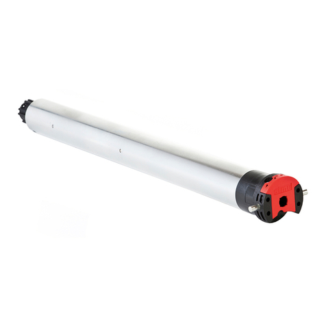
Simu T3.5EBHz User manual
Simu
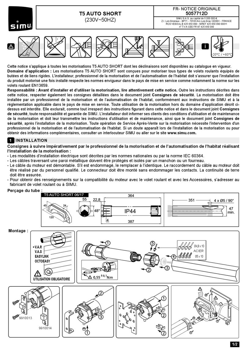
Simu 5057712D User manual
Simu
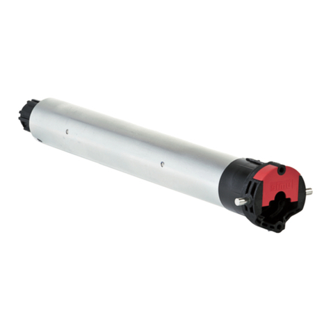
Simu T5 AUTO SHORT Hz User manual
Simu
Simu T5 AUTO+JOB Series User manual
Simu
Simu T5 AUTO User manual
Simu
Simu T5 AUTOSHORT BHz User manual
Simu
Simu T3.5EBHz User manual
Simu
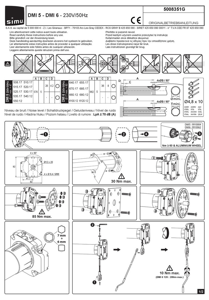
Simu DMI 6 User manual

Simu
Simu T5E-SP User manual
Simu
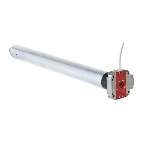
Simu DMI5 Hz User manual
Popular DC Drive manuals by other brands

Inovance
Inovance MD500-PLUS Series Hardware guide

ForceDoor
ForceDoor BASE 35 Instructions and user guide
LOVATO ELECTRIC
LOVATO ELECTRIC VLA1 series quick guide
Festo
Festo DRRD Series operating instructions
Rockwell Automation
Rockwell Automation Allen-Bradley PowerFlex 750 Series Service manual
BINZEL-ABICOR
BINZEL-ABICOR MFS-V3 operating instructions
