Simu Autosun 2 T3.5 EHz DC User manual

1/8
FR
PRÉSENTATION DU SYSTÈME AUTOSUN 2
i
-20°C / +60°C
i
S.A.S. au capital de 5 000 000 € - Z.I. Les Giranaux - BP71 - 70103 ARC-LÈS-GRAY CEDEX - FRANCE - RCS VESOUL B 425 650 090 - SIRET 425 650 090 00011 - n° T.V.A CEE FR 87 425 650 090
Cette notice s’applique à toutes les motorisations T3.5 EHz DC dont les déclinaisons sont disponibles au catalogue en vigueur.
Domaine d’application : Les motorisations T3.5 EHz DC sont conçues pour motoriser tous types de volets roulants. L’installateur,
professionnel de la motorisation et de l’automatisation de l’habitat doit s’assurer que l’installation, du produit motorisé une fois installé,
respecte les normes en vigueur dans le pays de mise en service comme notamment la norme sur les volets roulants EN13659.
Responsabilité : Avant d’installer et d’utiliser la motorisation, lire attentivement cette notice. Outre les instructions décrites
dans cette notice, respecter également les consignes détaillées dans le document joint Consignes de sécurité. La motorisation doit
être installée par un professionnel de la motorisation et de l’automatisation de l’habitat, conformément aux instructions de SIMU et
à la réglementation applicable dans le pays de mise en service. Toute utilisation de la motorisation hors du domaine d’application
décrit ci-dessus est interdite. Elle exclurait, comme tout irrespect des instructions gurant dans cette notice et dans le document joint
Consignes de sécurité, toute responsabilité et garantie de SIMU. L’installateur doit informer ses clients des conditions d’utilisation et
de maintenance de la motorisation et doit leur transmettre les instructions d’utilisation et de maintenance, ainsi que le document joint
Consignes de sécurité, après l’installation de la motorisation. Toute opération de Service Après-Vente sur la motorisation nécessite
l’intervention d’un professionnel de la motorisation et de l’automatisation de l’habitat. Si un doute apparaît lors de l’installation de la
motorisation ou pour obtenir des informations complémentaires, consulter un interlocuteur SIMU ou aller sur le site www.simu.com.
FR-
2
T3.5 EHz DC (12VDC)
5136882A
FR- NOTICE ORIGINALE
Le moteur T3.5 EHz DC fait partie du système Autosun 2 dont les références sont disponibles au catalogue en
vigueur. C’est un système de motorisation autonome fonctionnant à l’énergie solaire. L’énergie électrique fournie
par le panneau solaire est stockée dans la batterie du système. Ce système est prévu pour fonctionner dans
les pays suivants : France, Allemagne, Grande Bretagne, Belgique, Pays Bas, République Tchèque, Pologne,
Irlande, Espagne, Portugal, Italie, Grèce, Suisse, Luxembourg, Danemark, Autriche, Hongrie, États-Unis (hors
Alaska), Australie, et Turquie. Pour toute autre zone, veuillez nous contacter.
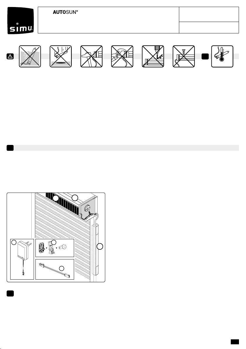
Le système Autosun 2 est composé de :
1- Moteur 12V T3.5 EHz DC, 3, 6 ou 10 Nm.
2- Panneau solaire 12 V : 3,2W / Voc : 21V / Isc : 196 mA.
3- Batterie NiMh 12 V : 2,2 Ah
En option :
4- Chargeur de batterie réf. : 9020638. Permet d’eectuer une
recharge rapide de la batterie du système Autosun 2.
5- Support panneau solaire réf. : 9019683
6- Rallonge pour panneau solaire 5 m réf. : 9019722
i• Le poids du volet roulant doit respecter les abaques déterminés pour chacun des moteurs.
• Les hauteurs maximum enroulables sont : 1600 mm pour un moteur de 3 Nm, 2400 pour un 6 Nm et 2700 pour
un 10 Nm.
• Ces préconisations sont déterminées à partir de données moyennes annuelles et pour une utilisation du
volet roulant à raison de 2 cycles / jour (1 cycle = 1 montée et 1 descente). Attention, 1 cycle maximum pour
moteur 10 Nm en cas d’orientation au Nord du panneau solaire. Pour les années avec un ensoleillement
exceptionnellement faible, se servir du chargeur pour recharger la batterie du système Autosun 2.
• Le panneau solaire doit toujours être positionné de manière à être exposé le plus possible au rayonnement du
soleil.
1
2
3
+ +
4
Réf. 9020638
Réf. 9019683
Réf. 9019722
6
5

2/8 FR
1
23
4
PLASTITE FXSN7/7X12 ZING JA.
(5005970)
1,2
40
9016635
=
INSTALLATION
1
Consignes à suivre impérativement par le professionnel de la motorisation et de l’automatisation de
l’habitat réalisant l’installation de la motorisation :
- Les modalités d’installation électrique sont décrites par les normes nationales ou par la norme IEC 60364.
- Les câbles traversant une paroi métallique doivent être protégés et isolés par un manchon ou un fourreau.
- Le câble du moteur n’est pas démontable. S’il est endommagé, retourner la motorisation au SAV.
Préconisations : Respecter une distance minimum de 20 cm entre deux moteurs T3.5 EHz DC. Respecter une
distance minimum de 30 cm entre un moteur T3.5 EHz DC et un émetteur Hz. SIMU recommande de placer les
connecteurs entre la joue et la asque, et de xer les câbles à l’intérieur du core du volet roulant. L’utilisation
d’un appareil radio utilisant la même fréquence (433,42 MHz) peut dégrader les performances de ce produit (ex. :
casque radio Hi-Fi).
Se référer à la notice 5117585/5139459 pour l’installation du panneau solaire.
Se référer à la notice 5136806/5139158 pour l’installation et la charge de la batterie. Charger la
batterie avant utilisation avec le chargeur réf. : 9020638
iLe moteur T3.5 EHz DC est compatible avec tous les émetteurs SIMU Hz (12 émetteurs (1 canal) max. par
moteur). Se référer aux notices correspondantes.
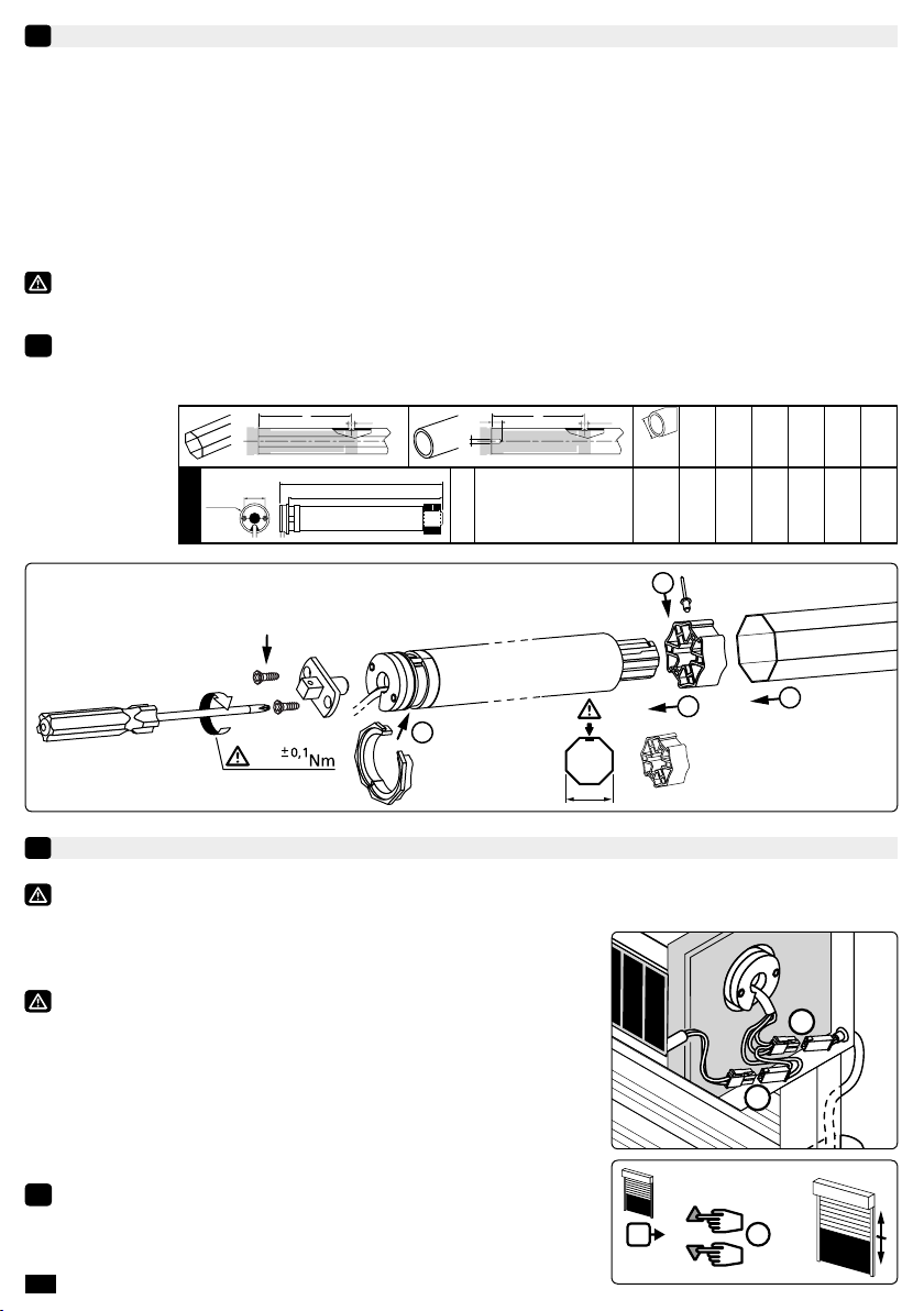
Perçage du tube :
Montage du moteur :
Ø min.
(mm)
A
(mm)
ØB
(mm)
C
(mm)
D
(mm)
L1
(mm)
L2
(mm)
AØB ØB
A
C
D
L2
L1
29
Ø38,2
T3.5 EHz D
C
12 VDC
3Nm - 6Nm - 10Nm 37 433 4,2 8 5,5 457 470
IP44
RÉGLAGE DES FINS DE COURSE
2
Si l’installation comporte plusieurs moteurs, un seul moteur doit être alimenté pendant les opérations
du chapitre 2.1, ceci pour éviter les interférences avec les autres moteurs lors de la programmation.
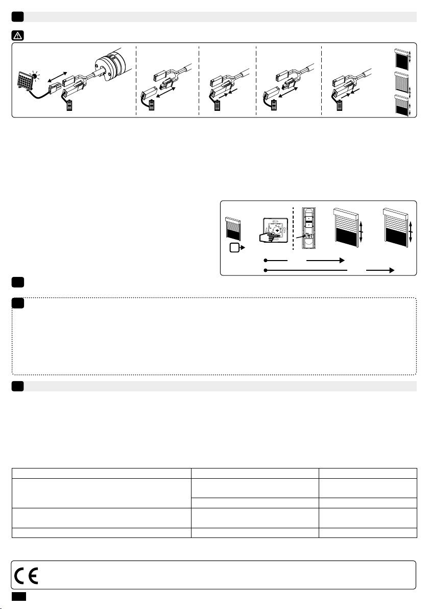
2.1- Mode apprentissage :
1- Connecter la batterie 12 V au moteur.
Dans le cas d’une alimentation autre que la batterie et le
panneau solaire du système Autosun 2, se référer au cahier
technique 5137581.
2- Ensuite, connecter le panneau solaire 12 V au moteur. Passer à
l’étape suivante.
3- Appuyer simultanément sur les touches « Montée » et
« Descente » d’un émetteur Hz. Le moteur eectue une rotation de
0,5 seconde dans un sens puis dans l’autre. Cet émetteur commande
maintenant le moteur en mode instable. Passer à l’étape 2.2.
iPendant les trois premières secondes de fonctionnement lors d’un
mouvement en montée ou en descente, le moteur fonctionne avec
une vitesse plus lente an de faciliter les réglages ns de course.
13>>
2
1
3/8
FR
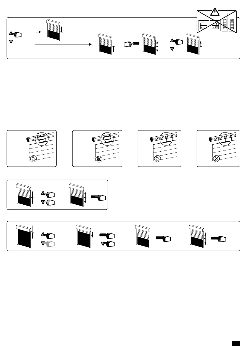
2.2- Conguration du sens de rotation :
Appuyer sur la touche « Montée » de l’émetteur :
a- Si l’axe tourne dans le sens montée, passer à l’étape 2.3.
b- Si l’axe tourne dans le sens descente, inverser le sens de rotation en appuyant sur la touche « Stop » pendant
au moins 3 secondes. Le moteur conrme la modication par une rotation de 0,5 seconde dans un sens puis
dans l’autre. Passer à l’étape 2.3.
2.3- Réglage des ns de course :
Le réglage des ns de course du moteur T3.5 EHz DC s’eectue de 4 façons diérentes en fonction des
paramètres suivants : Présence ou absence de butées sur la lame nale, liaison souple ou rigide* entre l’axe
d’enroulement et le tablier.
A
* V.A.R
V.A.S
Easylink
OctoEasy
B
* V.A.R
V.A.S
Easylink
OctoEasy
C
D
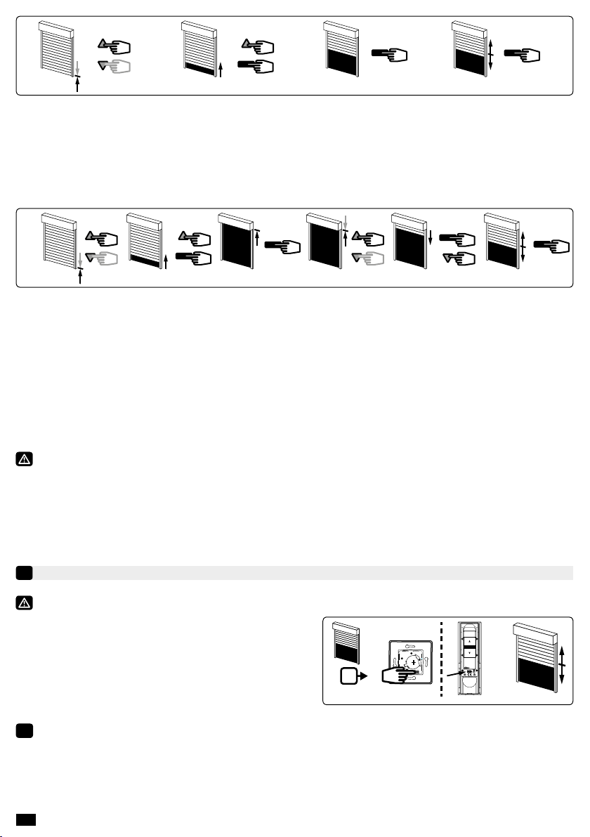
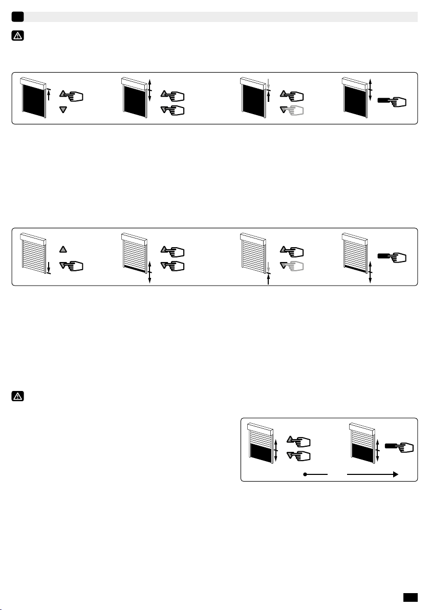
1- Appuyer simultanément sur les touches « Montée » et
« Descente » de l’émetteur Hz. Le moteur eectue une
rotation de 0,5 seconde dans un sens puis dans l’autre.
2- Appuyer sur la touche « Stop » pendant 2 s. Le moteur
eectue une rotation de 0,5 s. dans un sens puis dans
l’autre. L’opération est terminée. Passer au §3.
B123
2 s
4
1- Positionner le moteur sur le point d’arrêt haut souhaité à l’aide des touches « Montée » et « Descente ».
2- Appuyer simultanément sur les touches « Stop » et « Descente » pour mémoriser le point d’arrêt haut. Le
moteur se met automatiquement en rotation en descente.
3- Appuyer sur la touche « Stop » pour immobiliser le moteur.
4- Appuyer 2 secondes sur la touche « Stop » pour valider le réglage, le moteur eectue une rotation de
0,5 seconde dans un sens puis dans l’autre. L’opération est terminée. Passer au §3.
a
>>
>> OK >> 2.3
b>> >>
3 s
>> OK >> 2.3
2 s
A12

4/8 FR
C123
2 s
4
1- Positionner le moteur sur le point d’arrêt bas souhaité à l’aide des touches « Descente » et « Montée ».
2- Appuyer simultanément sur les touches « Stop » et « Montée » pour mémoriser le point d’arrêt bas. Le moteur
se met automatiquement en rotation en montée.
3- Appuyer sur la touche « Stop » pour immobiliser le moteur.
4- Appuyer 2 secondes sur la touche « Stop » pour valider le réglage, le moteur eectue une rotation de
0,5 seconde dans un sens puis dans l’autre. L’opération est terminée. Passer au §3.
D12 43
2 s
6
5
1- Positionner le moteur sur le point d’arrêt bas souhaité à l’aide des touches «Montée» et «Descente».
2- Appuyer simultanément sur les touches « Stop » et « Montée » pour mémoriser le point d’arrêt bas. Le
moteur se met automatiquement en rotation en montée.
3- Lorsque le moteur arrive au point d’arrêt haut souhaité, appuyer sur la touche «Stop».
4- Si nécessaire, aner le réglage à l’aide des touches «Montée» et «Descente».
5- Appuyer sur les touches « Stop » et « Descente » pour mémoriser le point d’arrêt haut. Le moteur se met
automatiquement en rotation en descente.
6- Appuyer 2 secondes sur la touche « Stop » pour valider les réglages n de course. Le moteur s’arrête puis
eectue une rotation de 0,5 seconde dans un sens puis dans l’autre. L’opération est terminée. Passer au §3.
Si vous souhaitez programmer un autre émetteur que celui utilisé jusqu’à présent comme point de
commande du moteur :
- couper l’alimentation du moteur (2 secondes minimum).
- reprendre l’opération 2.1* avec un nouvel émetteur avant de passer au chapitre 3.
* A la mise sous tension le moteur eectue une courte rotation dans un sens puis dans l’autre, ce qui
indique que les ns de course sont déjà réglés.
PROGRAMMATION DU PREMIER POINT DE COMMANDE INDIVIDUELLE
3
Cette opération ne peut être eectuée que depuis l’émetteur ayant eectué l’opération 2.1.
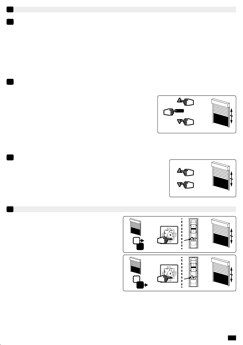
- Appuyer environ 1 seconde sur la touche PROG
de l’émetteur. Le moteur eectue une rotation de
0,5 seconde dans un sens puis dans l’autre.
i- Votre émetteur est maintenant programmé et commande le moteur en mode stable.
- La radio du moteur peut être mise en veille pendant 10 minutes, après cette opération (voir §4).
1
>>
PROG 1 s
5/8
FR
MISE EN VEILLE / RÉVEIL DU MOTEUR
4
iIl est possible de mettre la radio du moteur en veille an :
- de limiter la décharge de la batterie pendant les périodes où le panneau solaire n’est pas en mesure de
fonctionner normalement (emballage du volet roulant, transport, stockage…).
- d’empêcher tout risque de manœuvre intempestive (transport, stockage…).
Après la pose du volet roulant, il sura de réveiller le moteur pour poursuivre la programmation
des autres points de commande.
4.1 Mise en veille de la radio du moteur :
iIl n’est possible d’activer la mise en veille qu’après avoir enregistré le premier point de commande au §3 et
avant d’avoir procédé aux programmations du §5 (pendant 10 min max., ou pendant les 10 min qui suivent
une coupure d’alimentation depuis la batterie et du panneau solaire en simultané).
- Appuyer simultanément sur les touches « Montée »,
« Stop » et « Descente » de l’émetteur (programmé au §3)
pendant plus de 3 secondes. Le moteur eectue une rotation
de 0,5 seconde dans un sens puis dans l’autre.
La radio du moteur est mise en veille.
4.2 Réveil de la radio du moteur :
iLe réveil du moteur n’est possible que si le panneau solaire est connecté au moteur et éclairé (lumière diuse
du soleil, lampe de poche…).
- Appuyer simultanément sur les touches « Montée » et
« Descente » pendant 10 secondes. Le moteur eectue une
rotation de 0,5 seconde dans un sens puis dans l’autre.
Le moteur est de nouveau fonctionnel.
>>
> 3 s
>>
10 s
PROGRAMMATION D’UN NOUVEAU POINT DE COMMANDE (INDIVIDUEL, GROUPÉ OU GÉNÉRAL)
5
5.1- Ouvrir la mémoire du moteur depuis l’émetteur
de commande individuelle :
- Appuyer environ 3 secondes sur la touche PROG
de l’émetteur de commande individuelle. Le moteur
eectue une rotation de 0,5 seconde dans un sens puis
dans l’autre.
5.2- Valider l’opération depuis le nouvel émetteur à
programmer :
- Appuyer environ 1 seconde sur la touche PROG du
nouvel émetteur. Le moteur eectue une rotation de
0,5 seconde dans un sens puis dans l’autre.
- Si votre nouveau point de commande est une commande de groupe : répéter les opérations 5.1 et 5.2 pour
chaque moteur du groupe.
- Si votre nouveau point de commande est une commande générale : répéter les opérations 5.1 et 5.2 pour
chaque moteur de l’installation.
- Pour supprimer un émetteur de la mémoire du moteur : Eectuer les opérations 5.1 depuis l’émetteur de
commande individuelle et l’opération 5.2 depuis l’émetteur à supprimer.
1
>>
PROG ≥ 3 s
>>
PROG < 1 s
2
6/8 FR
FONCTIONNEMENT DU MOTEUR T3.5 EHzDC
6
6.1 - Avec une batterie en bon état de charge, les commandes possibles sont : Montée, Stop et Descente.
- Le moteur ralentira en arrivant en n de course haute / basse.
- Il eectuera un démarrage avec une vitesse plus lente après une commande de « Montée » depuis la n
de course basse.
- Il est également possible de commander/modier une position intermédiaire (voir §7).
6.2 - Fonction détection du gel : Un blocage du volet en présence de gel à la montée provoque l’arrêt du
moteur.
6.3 - Fonction détection d’obstacle : Un blocage du volet en présence d’un obstacle à la descente provoque
l’arrêt du moteur, et une inversion du mouvement.
6.4 - Fonction protection de la batterie contre la décharge excessive : Avant chaque opération de montée ou
de descente, le moteur contrôle la tension de la batterie :
- Si la tension est inférieure à 12 V: Il ne sera plus possible d’eectuer des opérations de programmation du
moteur (§2->§9).
- Si la tension est inférieure à 11,5 V : Le moteur marquera un temps d’arrêt au début de chaque ordre de
montée. La descente n’est possible qu’en donnant plusieurs impulsions sur la touche “Descente”.
- Si la tension est inférieure à 10 V : Le moteur n’acceptera aucun ordre de commande.
iDans tous ces cas, utiliser le chargeur de la batterie an d’eectuer une recharge rapide de la
batterie. Le fonctionnement du moteur redeviendra normal uniquement si la tension de la batterie
remonte au dessus de 12 V.
ATTENTION : Ne jamais laisser une batterie déchargée (un état de décharge prolongé peut
l’endommager).
ENREGISTREMENT / COMMANDE / SUPPRESSION DE LA POSITION INTERMÉDIAIRE
7
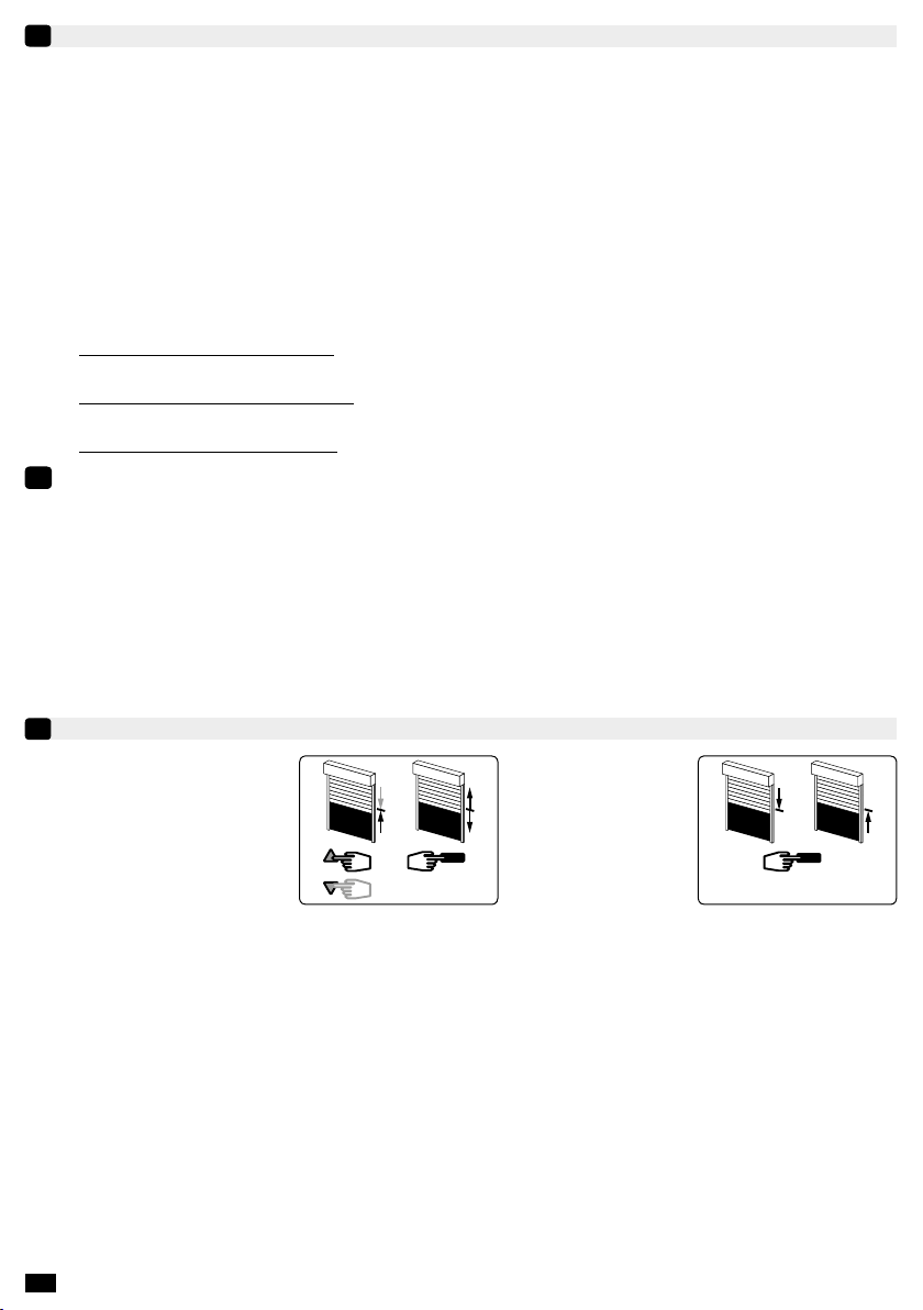
Enregistrement :
- Positionner le moteur sur la
position intermédiaire désirée.
- Appuyer 5ssur la touche
« Stop ». Le moteur eectue
une rotation de 0,5 s dans un
sens puis dans l’autre.
5 s
Commande :
- Appuyer sur la touche
« Stop » pendant
0,5 s. Le moteur
rejoint la position
intermédiaire.
0,5 s
Suppression :Positionner le moteur sur la position intermédiaire. Appuyer 5 s sur la touche « Stop ». la position
intermédiaire est supprimée.
7/8
FR
MODIFICATION DES POSITIONS DE FINS DE COURSE ET DU SENS DE ROTATION (EN MODE UTILISATEUR)
8
Le ré-ajustement est automatique tous les 60 cycles (pendant 4 cycles) ou après une coupure d’alimentation
dans les cas suivants : Fin de course Haut, montages A et C, n de course bas, montages A et B.
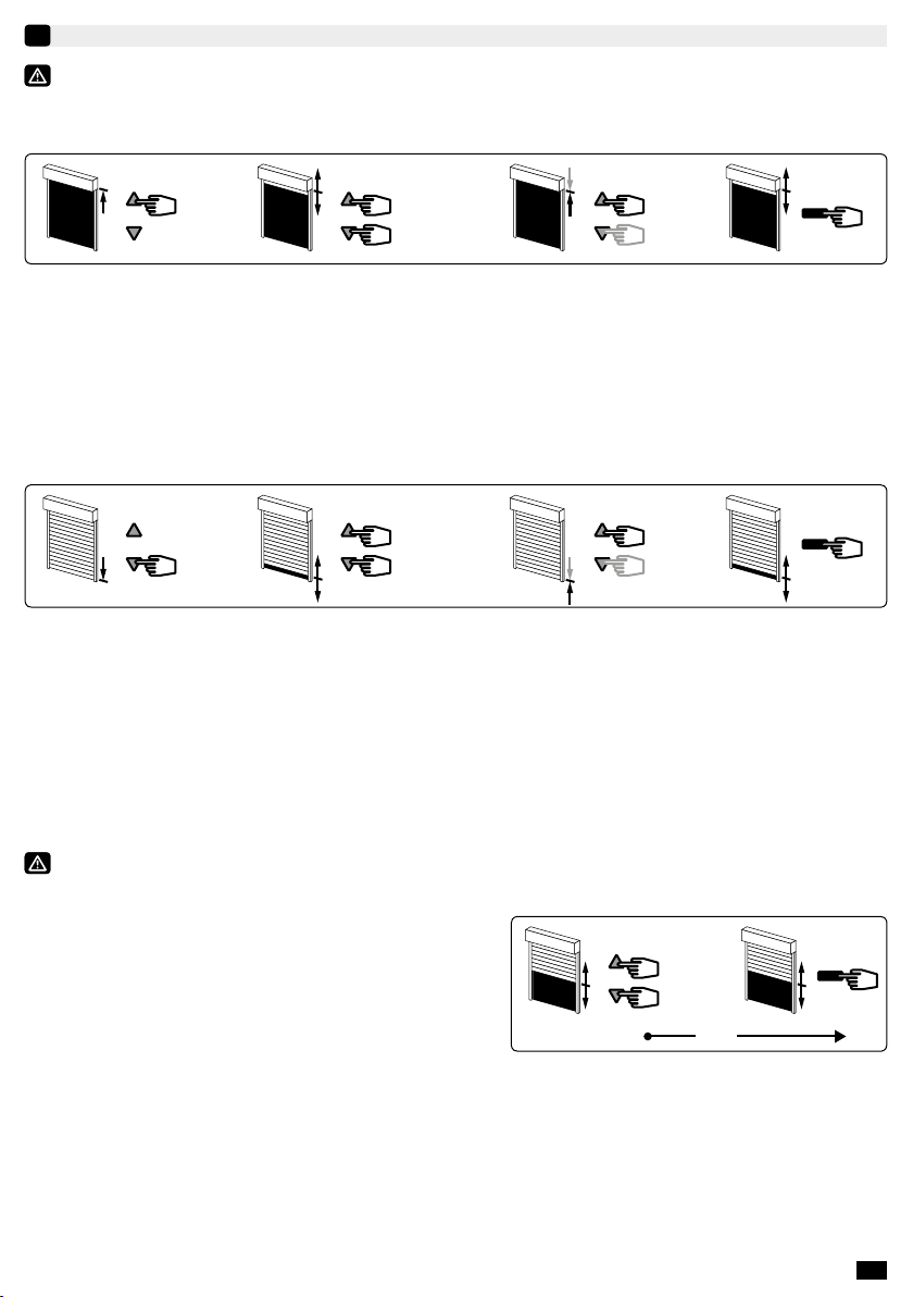
8.1- Modication de la position de n de course haute (montages B et D uniquement) :
1
> 2 s
4
32
5 s
1- Positionner le moteur sur le point d’arrêt haut réglé en §2.3 à l’aide de la touche « Montée ».
2- Appuyer simultanément sur les touches « Montée » et « Descente » pendant 5 secondes. Le moteur eectue
une rotation de 0,5 seconde dans un sens puis dans l’autre.
3-
Aner le réglage à l’aide des touches « Descente » et « Montée» pour obtenir la position de n de course souhaitée.
4- Appuyer 2 secondes sur la touche « Stop ». Le moteur eectue une rotation de 0,5 seconde dans un sens puis
dans l’autre, la nouvelle position de n de course est mémorisée.
8.2- Modication de la position de n de course basse (montages C et D uniquement) :
1 4
> 2 s
3
2
5 s
1- Positionner le moteur sur le point d’arrêt bas réglé en §2.3 à l’aide de la touche « Descente ».
2- Appuyer simultanément sur les touches « Montée » et « Descente » pendant 5 secondes. Le moteur eectue
une rotation de 0,5 seconde dans un sens puis dans l’autre.
3- Aner le réglage à l’aide des touches « Descente » et « Montée » pour obtenir la position de n de course
souhaitée.
4- Appuyer 2 secondes sur la touche « Stop ». Le moteur eectue une rotation de 0,5 seconde dans un sens puis
dans l’autre, la nouvelle position de n de course est mémorisée.
8.3- Modication du sens de rotation :
Ne pas positionner le volet roulant en n de course haute ou basse.
1 - Appuyer simultanément sur les touches « Montée » et
« Descente » de l’émetteur pendant 5 secondes. Le
moteur tourne 0.5 seconde dans un sens puis dans l’autre.
2 - Dans un délai de 2 secondes, appuyer sur la touche
« Stop » de l’émetteur pendant 2 secondes. Le moteur
tourne 0.5 seconde dans un sens puis dans l’autre. Le
sens de rotation est inversé.
2
> 2 s
1
5 s
2 s
8/8 FR
iIl est possible d’eectuer la procédure de double coupure d’alimentation depuis le connecteur du
panneau solaire, (sans intervenir sur le connecteur de la batterie), si les deux conditions suivantes
sont réunies :
- la radio du moteur doit être en veille (voir §4)
- le panneau solaire doit être éclairé depuis moins de 10 min (lumière diuse du soleil, lampe de poche…).
S’il est éclairé depuis plus de 10 minutes, déconnecter le panneau solaire pendant 10 secondes.
- Eectuer ensuite la procédure 9.2, 9.3, 9.4, 9.5, depuis le connecteur du panneau solaire (en conservant
la connexion du moteur à la batterie), avant d’eectuer l’opération 9.6.
UTILISATION ET MAINTENANCE
10
- Cette motorisation ne nécessite pas d’opération de maintenance.
- Appuyer sur la touche ▲du point de commande pour faire monter le produit motorisé.
- Appuyer sur la touche ▼ du point de commande pour faire descendre le produit motorisé.
-
Quand le produit motorisé est en cours de mouvement, un appui bref sur la touche « Stop » arrête le produit motorisé.
- Quand le produit motorisé est à l’arrêt, un appui bref sur la touche « Stop » commande le produit motorisé sur la
position intermédiaire programmée. (Pour modier ou supprimer une position intermédiaire voir le chapitre §7).
Astuces et conseils d’utilisation :
Constats Causes possibles Solutions
Le produit motorisé ne fonctionne pas.
La pile du point de commande est
faible.
Contrôler si la pile est faible
et la remplacer si besoin.
La batterie du système est faible. Recharger la batterie.
Le produit motorisé marque un temps d’arrêt avant
de monter, lors d’un appui sur la touche « Montée ».
La batterie du système est faible. Recharger la batterie.
La programmation du moteur est impossible. La batterie du système est faible. Recharger la batterie.
Si le produit motorisé ne fonctionne toujours pas, contacter un professionnel de la motorisation et de l’automatisation de l’habitat.
Par la présente, SIMU SAS, F-70103 GRAY déclare en tant que fabricant que la motorisation couverte par ces instructions et utilisée
comme indiqué dans ces instructions, est conforme aux exigences essentielles des Directives Européennes applicables et en particulier
à la Directive Machine 2006/42/EC et à la Directive Radio 2014/53/EU. Emmanuel CARMIER, directeur général, GRAY, 10/2017.
ANNULATION DE LA PROGRAMMATION
9
Durant les opérations de ce chapitre (§9), ne pas travailler sur plusieurs moteurs simultanément.
>>>>
9.1- 9.2- 9.3-
5 s
7s
9.4- 9.5-
2s 2s
9.1- Déconnecter le panneau solaire du moteur T3.5 EHz DC
9.2- Déconnecter la batterie du moteur T3.5 EHz DC pendant 2 secondes.
9.3- Connecter la batterie au moteur pendant 7 secondes.
9.4- Déconnecter la batterie du moteur pendant 2 secondes.
9.5- Rétablir la connexion. Si le moteur se trouve en position de n de course (haute ou basse), il eectue
une brève rotation dans les deux sens. S’il se trouve dans une autre position, il eectue une rotation de
5 secondes dans un sens quelconque.
Le moteur est maintenant en mode « annulation de la programmation ».
9.6- Ensuite valider l’annulation de la programmation
du moteur concerné depuis l’émetteur de commande
individuelle ou depuis un nouvel émetteur :
-
Appuyer plus de 7 secondes sur la touche PROG de
l’émetteur. Maintenir l’appui jusqu’à ce que le moteur
eectue une première rotation de 0,5 seconde dans un
sens puis dans l’autre, puis quelques secondes plus tard
une seconde rotation de 0,5 seconde dans les deux sens.
iLa mémoire du moteur est maintenant complètement vidée. Vous pouvez reconnecter le panneau solaire,
puis eectuer de nouveau la programmation complète du moteur (§2).
9.6-
1
>> >>
PROG > 7 s
2 s
7 s
EN 1/8
AUTOSUN 2 SYSTEM PRESENTATION
i
-20°C / +60°C
i
S.A.S. au capital de 5 000 000 € - Z.I. Les Giranaux - BP71 - 70103 ARC-LÈS-GRAY CEDEX - FRANCE - RCS VESOUL B 425 650 090 - SIRET 425 650 090 00011 - n° T.V.A CEE FR 87 425 650 090
These instructions apply to all T3.5 EHz DC drive, the dierent versions of which are available in the current catalogue.
Field of application: T3.5 EHz DC drive are designed to all types of roller shutters. The installer, who must be a motorisation and home
automation professional, must ensure that the drive product is installed in accordance with the standards in force in the country in which
it is installed such as EN 13659 relating to roller shutters.
Liability: Before installing and using the drive, please read operating and installation guide carefully. Please read these
instructions carefully before installing and using the drive. In addition to following the instructions given in this guide, the instructions
detailed in the attached Safety instructions document must also be observed. The drive must be installed by a motorisation and home
automation professional, according to instructions from SIMU and the regulations applicable in the country in which it is commissioned.
It is prohibited to use the drive outside the eld of application described above. Such use, and any failure to comply with the instructions
given in this guide and in the attached Safety instructions document, absolves SIMU of any liability and invalidates the warranty. The
installer must inform its customers of the operating and maintenance conditions for the drive and must provide them with the instructions
for use and maintenance, and the attached Safety instructions document, after installing the drive. Any After-Sales Service operation
on the drive must be performed by a motorisation and home automation professional. If in doubt when installing the drive, or to obtain
additional information, contact a SIMU adviser or go to the website www.simu.com.
EN-
2
T3.5 EHz DC (12VDC)
5136882A
EN- ORIGINAL INSTRUCTIONS
The T3.5 EHz DC motor is part of the Autosun 2 system which references are available in the current catalogue.
It is a powered system working with solar energy. The electrical energy supplied by the solar panel is stored
inside the battery of the system. This system was developed to run into the following countries: France, Germany,
England, Belgium, Netherlands, Czech Republic, Poland, Ireland, Spain, Portugal, Italy, Greece, Switzerland,
Luxembourg, Denmark, Austria, Hungary, USA (excluding Alaska), Australia and Turkey. For other countries,
please contact us.
Autosun 2 system components:
1- 12V motor T3.5 EHz DC, 3, 6 or 10 Nm.
2- SOLAR PANEL 12V: 3.2W / Voc: 21V / Isc : 196 mA.
3- Battery NiMh 12V: 2.2Ah
In option:
4- Battery charger ref. 9020638. Allows rapid recharging of the
battery for the Autosun 2 system.
5- Solar Panel bracket ref.: 9019683
6- Extension cable 5m ref.: 9019722
i• The weight of roller shutter must comply with the charts determined for the motors. Maximum shutter heights
are: 1600 mm for 3Nm motors, 2400 mm for 6Nm motors and 2700 mm for 10Nm motors.
• These consign are based on average annual data and for a roller shutter used for 2 cycles/day (1 cycle = 1 up
and 1 down movement). Caution 1 cycle maximum for the 10 Nm motor when North orientation (or South
orientation for Australia only). In exceptional years, use the battery charger to recharge the Autosun 2 ’s battery.
• The solar panel should always be placed on the shutter housing so as to be as exposed as possible to the sun’s
rays.
1
2
3
+ +
4
Ref. 9020638
Ref. 9019683
Ref. 9019722
6
5
EN
2/8
1
23
4
PLASTITE FXSN7/7X12 ZING JA.
(5005970)
1,2
40
9016635
=
INSTALLATION
1
Instructions which must be followed by the drive and home automation professional installing the drive:
- Methods of wiring are given by national standards or IEC60364 standard.
- Cables which pass through a metal wall must be protected and isolated using a sheath or sleeve.
- The cable for the motor cannot be removed. If it is damaged, return the drive to the After-Sales department.
Recommendations: Keep a minimum distance of 20 cm between two T3.5 EHz DC motors. Keep a minimum
distance of 30 cm between T3.5 EHz DC motors and Hz transmitters. Simu recommends placing the connectors
between the end piece and ange, and xing the cables inside the roller shutter box. The cables and connectors
must be protected from the roller shutter movement. A radio appliance using the same frequency (433,42MHz)
may deteriorate our product’s performance (ex.: hi- radio headphones). Do not position the transmitter near
metal in order to avoid range losses.
Refer to instruction 5117585/5139459 for solar panel installation.
Refer to instruction 5136806/5139158 for battery installation. Recharge the battery before use with
the charger ref. 9020638.
iThe T3.5 EHz DC motor is compatible with all Simu Hz transmitters (12 transmitters (1 channel) max. for one
motor). Please refer to the corresponding instructions.
Drilling of the tube:
Mounting:
Ø min.
(mm)
A
(mm)
ØB
(mm)
C
(mm)
D
(mm)
L1
(mm)
L2
(mm)
AØB ØB
A
C
D
L2
L1
29
Ø38,2
T3.5 EHz D
C
12 VDC
3Nm - 6Nm - 10Nm 37 433 4,2 8 5,5 457 470
IP44
END LIMIT ADJUSTMENT
2
If the installation includes several motors, only one motor should to be powered during this programming
procedure 2.1. It will eliminate interferences with the other motors during the procedure.
2.1- Learning mode:
1- Connect the 12V battery to the motor.
When using another power supply than Autosun 2 system battery
and solar panel, please refer to the technical booklet 5139543.
2- Then, connect the 12V solar panel to the motor. Go to next step.
3- Press simultaneously on the “UP” and “DOWN” buttons of the Hz
transmitter. The motor turns 0.5 second in one direction, then in the
other. This transmitter now commands the motor in unstable mode.
Go to step 2.2.
i During the rst three seconds of running during a Up or Down
movement, the motor will operate with slower speed to ease the limit
setting.
13>>
2
1

EN 3/8
2.2- Checking the rotation direction:
Press the “UP” button of the transmitter :
a- If the motorized tube runs in the Up direction, move to next stage 2.3.
b- If the motorized tube runs in the Down direction, reverse the rotation direction by pressing the “STOP” button
for at least 3 seconds. The motor will run for 0,5 second in one direction, then in the other direction. Move to the
stage 2.3.
2.3- End limit adjustment:
The end limits of the T3.5 EHz DC are adjusted in 4 dierent ways depending on the following conditions : Bottom
slat stop or not, rigid* or exible link between the rolling shaft and the shutter.
A
* V.A.R
V.A.S
Easylink
OctoEasy
B
* V.A.R
V.A.S
Easylink
OctoEasy
C
D
1- Simultaneously press the “UP” and “DOWN” buttons
of a Hz transmitter. The motor will run for 0.5 second in one
direction and then in the other.
2- Press the “STOP” button for 2 s. The motor will run
for 0.5 second in one direction and then in the other. The
operation is completed. Go to step §3.
B123
2 s
4
1- Position the motor on the Up end limit by using the buttons “UP” or “DOWN”.
2- To memorize the UP end limit position, press simultaneously the buttons “STOP” and “DOWN”. The motor will
run automatically in the down direction.
3- Press the “STOP” button to immobilize the motor.
4- Press 2 seconds the “STOP” button to validate the setting. The motor will run for half a second in one
direction, then in the other direction. The operation is completed. Go to step §3.
a
>>
>> OK >> 2.3
b>> >>
3 s
>> OK >> 2.3
2 s
A12
EN
4/8
C123
2 s
4
1- Position the motor on the Down end limit by using the buttons “UP” or “DOWN”.
2- To memorize the Down end limit position, press simultaneously the buttons “STOP” and “UP”. The motor
will run automatically in the UP direction.
3- Press the “STOP” button to immobilize the motor.
4- Press 2 seconds the “STOP” button to validate the setting. The motor will run for 0.5 second in one direction,
then in the other. The operation is completed. Go to step §3.
D12 43
2 s
6
5
1- Position the motor on the Down end limit by using the buttons “DOWN” or “UP”.
2- To memorize the Down end limit position, press simultaneously the buttons “STOP” and “UP”. The motor
will run automatically in the Up direction.
3- When the motor arrives on the Up End limit, press the button “STOP”.
4- If necessary adjust the position with the button “UP” or “DOWN”.
5- To memorize the Up end limit position, press simultaneously the buttons “STOP” and “DOWN”. The motor
will run automatically in the Down direction.
6- Press 2 seconds the “STOP” button to validate the setting. The motor will stop, and will run for 0.5 second in
one direction, then in the other. The operation is completed. Go to step §3.
If you do not want to use this transmitter as the individual control:
- cut the power supply (2 seconds minimum).
- repeat the operation 2.1* with a new transmitter and then go to step §3.
* In this case, the motor will run for 0,5 second in both directions, that means the limits setting is already
done.
PROGRAMMING THE FIRST INDIVIDUAL CONTROL POINT
3
This operation can only be performed from the transmitter that was used for operation 2.1.
- Press the transmitter “PROG” key for approximately
one second. The motor will run for 0.5 second in
one direction and then in the other.
i- Your transmitter is now programmed to control the motor in stable mode.
- After this operation it is possible for 10 minutes to put the motor in stand by mode (see §4).
1
>>
PROG 1 s

EN 5/8
MOTOR STAND BY / WAKE UP
4
iIt is possible to put the motor in stand by (radio de-activated) to:
- limit the battery discharge when the solar panel is unable to operate normally (packaging of the roller
shutter, transport, storage,…)
- eliminate any risk of random use (packaging of the roller shutter, transport).
After installation of the roller shutter, normal operation will be restored by woken up the motor
(radio re-activated).
4.1 Motor’s radio Stand-by :
iIt is only possible to put the motor in standby after programming the rst control point in §3 and before
performing the programming of the § 5 (for 10 min max. or during the 10 min following a simultaneously
power cut from the battery and from the solar panel).
- Press simultaneously and for 3 seconds the “UP” / “STOP”
and “DOWN” buttons from transmitter (programmed in §3), the
motor will run for 0.5 second in one direction and then in the
other direction. The motor’s radio is de-activated.
4.2 Motor’s radio wake up:
iWake up is only possible if the solar panel is connected to the motor and illumated (diuse sun light,
ashlight,…at minimum).
- Press simultaneously and for more than 10 seconds the “UP”
and “DOWN” buttons of the programmed transmitter. The motor will
run for 0.5 second in one direction and then in the other direction.
The motor’s radio is waked up. The motor work now normally.
>>
> 3 s
>>
10 s
PROGRAMMING A NEW (INDIVIDUAL, GROUP OR MAIN) CONTROL POINT
5
5.1- Open the memory of the receiver from the
control transmitter:
- Press the “PROG” key of the transmitter for about
3 seconds. The motor will run for 0,5 second in one
direction and then in the other.
5.2- Conrm the operation from the new transmitter
you want to program:
- Press the “PROG” key of the transmitter for 1 second.
The motor will run for 0,5 second in one direction and
then in the other.
- For group controls, repeat operations 5.1 and 5.2 for each motor in the group.
- For general controls, repeat operations 5.1 and 5.2 for each motor in the installation.
- To delete an transmitter from the memory of a motor, perform operations 5.1 with a programmed transmitter,
then perform the operation 5.2 with the transmitter to be deleted.
1
>>
PROG ≥ 3 s
>>
PROG < 1 s
2

EN
6/8
T3.5 EHzDC FUNCTIONING
6
6.1 - With a well charged battery, the possible commands are: Up, Stop and Down.
- The motor slows down at the UP & Down end-limit.
- The motor will start with a slower speed after a “UP” order starting from the Down end-limit position.
- It is also possible to set an intermediate position (see §7).
6.2 - Frost detection function: The motor stops if the shutter is stuck by ice during opening.
6.3 - Obstacle detection function: When closing the shutter if the motor is stuck by an obstacle, the motor will
stop & then run in the reverse direction.
6.4 - Battery protection against excessive discharge: Before each downward or upward movement of the
shutter, the motor checks the voltage of the battery:
- If the voltage is below 12V: It would not be possible to perform the programming of the motor (§2 -> §9).
- If the voltage is below 11,5V: The motor will pause at the beginning of each command to lift the shutter. The
shutter can only be closed by pressing several times on the «down» button.
- If the voltage is below 10V: The motor won’t accept any order.
iIn these cases, use the battery charger in order to perform a quick battery recharge. Operation of the
motor will go back to normal only if the battery voltage reaches above 12V.
WARNING: Never leave a battery discharged (the battery can be damaged by being left in a discharged
condition for an extended period).
RECORDING / CONTROLING / DELETING INTERMEDIATE POSITION
7
Recording:
- Move the motor to the wanted
position.
- Press 5 seconds on the
« STOP » button. The motor
will run for 0,5 second in one
direction and then in the other.
5 s
Control:
- Press the « STOP »
button for 0,5 second.
The motor runs to the
intermediate position.
0,5 s
Deleting: Position the motor on the intermediate position. Press 5 seconds on the “Stop” button, the intermediate
position is deleted.
EN 7/8
RE-ADJUSTMENT OF END LIMITS AND MODIFICATION OF THE ROTATION DIRECTION (IN USER MODE)
8
The re-adjustment of end limits is automatic every 60 cycles (during 4 cycles) or after a battery disconnection
for the following installation: UP end limit, mounting A and C, DOWN end limit, mounting A and B.
8.1- Re-adjustment of Up end limit (mounting B and D only):
1
> 2 s
4
32
5 s
1- Move the motor to the Up end limit previously adjusted in §2.3 with the “UP” button.
2- Press simultaneously for 5 seconds the “UP” and “DOWN” buttons. The motor will run for 0,5 second in one
direction and then in the other direction.
3- Adjust the new position with the “UP” and “DOWN” buttons.
4- Conrm the new position by pressing 2 seconds the “STOP” button. The motor will run for 0,5 second in one
direction and then in the other direction. The new end limit is memorized.
8.2- Re-adjustment of Down end limit (mounting C and D only):
1 4
> 2 s
3
2
5 s
1- Move the motor to the Down end limit previously adjusted in §2.3 with the “DOWN” button.
2- Press simultaneously for 5 seconds the “UP” and “DOWN” buttons, The motor will run for 0,5 second in one
direction and then in the other direction.
3- Adjust the new position with the “UP” and “DOWN” buttons.
4- Conrm the new position by pressing 2 seconds the “STOP” button. The motor will run for 0,5 second in one
direction and then in the other direction. The new end limit is memorized.
8.3- Modication of the rotation direction :
Do not move the roller shutter to the up or down end limit position.
1 - Press the “UP” and “DOWN” buttons simultaneously for
5 seconds. The motor runs briey in one direction, then
in the other.
2 - Within 2 seconds, press the “STOP” button for
2 seconds. The motor briey runs in one direction, then in
the other. The rotation direction has been changed.
2
> 2 s
1
5 s
2 s

EN
8/8
iIt is possible to perform the double power-cut procedure directly from the solar panel’s connector
(without disconnecting the battery from the motor), if the following two conditions are met:
-The motor radio must be in standby mode (see § 4).
- The solar panel must be illuminated by diuse sunlight, ashlight, ...for less than 10 min. If it is illuminated
for more than 10 minutes, disconnect the solar panel for 10 seconds.
-Then follow double power-cut procedure 9.2, 9.3, 9.4, 9.5, from the solar panel connector (the connection
between battery and the motor is kept), before carrying out operation 9.6.
OPERATION AND MAINTENANCE
10
- This drive is maintenance-free.
- Press the ▲ button on the control point to raise the motorised product.
- Press the ▼ button on the control point to lower the motorised product.
- If the motorised product is moving, briey press the “Stop” button, the motorised product stop automatically.
- The motorised product is then stopped, briey press the “Stop” button, the motorised product moves to the
programmed intermediate position. (To modify or delete an intermediate position, see the section §7).
Tips and recommendations for use:
Problems Causes possibles Solutions
The motorised product is not operational.
The battery of the control point is
low.
Check the battery and
replace is as required.
The battery of the system is low Recharge the battery
The motorised product stops briey before rising
when the Up button is pressed.
The battery of the system is low Recharge the battery
The programming of the motor is not possible. The battery of the system is low Recharge the battery
If the motorised product still does not work, contact a drive and home automation professional.
SIMU SAS, F-70103 GRAY as manufacturer hereby declares that the drive covered by these instructions and used as intended according to these instructions
is in compliance with the essential requirements of the applicable European Directives and in particular of the Machinery Directive 2006/42/EC, and the Radio
Directive 2014/53/EU. The full text of the EU declaration of conformity is available at www.simu.com. Emmanuel CARMIER, general director, GRAY, 10/2017.
CANCELLING PROGRAMMING
9
During the operations in this section (§9), do not work on several motors at the same time.
>>>>
9.1- 9.2- 9.3-
5 s
7s
9.4- 9.5-
2s 2s
9.1 - Disconnect the solar panel from the T3.5 EHz DC motor
9.2 - Disconnect the battery from the T3.5 EHz DC motor for 2 seconds.
9.3 - Connect the battery to the motor for 7 seconds.
9.4 - Disconnect the battery from the motor for 2 seconds.
9.5 - Restore the power supply. If the motor is on the end limit position (up or down), the motor will run briey in
one direction and then in the other, otherwise, the motor runs for 5 seconds in random direction.
The motor is now in the « cancelling mode”.
9.6 - Then, conrm the cancelling of the concerned
motor from the individual control:
- Press the PROG key of the transmitter more than
7 seconds. Maintain the pressure until the motor will
rst run for 0,5 second in one direction and then in the
other, and a few second later, it will run again in both
direction.
iThe memory of the motor is now completely deleted. You can connect the solar panel onto the battery, and
then proceed to the complete programming (§2).
9.6-
1
>> >>
PROG > 7 s
2 s
7 s

DE 1/8
BESCHREIBUNG AUTOSUN 2 SYSTEM
i
-20°C / +60°C
i
S.A.S. au capital de 5 000 000 € - Z.I. Les Giranaux - BP71 - 70103 ARC-LÈS-GRAY CEDEX - FRANCE - RCS VESOUL B 425 650 090 - SIRET 425 650 090 00011 - n° T.V.A CEE FR 87 425 650 090
Diese Anleitung gilt für alle Antriebe vom Typ T3.5 EHz DC, deren Ausführungen im aktuellen Katalog zu nden sind.
Bestimmungsgemäße Verwendung: Die Antriebe T3.5 EHz DC sind für den Antrieb aller Arten von Rollläden. Der Installateur, ein
Fachmann für Gebäudeautomation, muss sicherstellen, dass die Installation des Antriebs nach Montage den geltenden Vorschriften
des Ortes der Inbetriebnahme entspricht. Hierzu gehören insbesondere die Norm: EN13659 (Rollläden).
Haftung: Lesen Sie bitte vor der Montage und Verwendung des Antriebs diese Installationsanleitung sorgfältig durch. Beachten
Sie außer den Anweisungen in dieser Anleitung auch die detaillierten Hinweise im beiliegenden Dokument „Sicherheitshinweise“.
Die Installation des Antriebs muss von einem Fachmann für Gebäudeautomation unter Einhaltung der Anweisungen von SIMU
und der am Ort der Inbetriebnahme geltenden Vorschriften ausgeführt werden. Jede Nutzung des Antriebs zu Zwecken, die über
den im vorliegenden Dokument beschriebenen Anwendungsbereich hinausgehen, ist untersagt. Jede Missachtung dieser, sowie
aller anderen in dieser Anleitung und im beiliegenden Dokument „Sicherheitshinweise“ enthaltenen Anweisungen führt zum
Ausschluss jeglicher Haftung und Gewährleistungsansprüche durch SIMU. Der Installateur hat seine Kunden auf die Nutzungs-und
Wartungsbedingungen des Antriebs hinzuweisen und ihnen diese sowie das beiliegende Dokument „Sicherheitshinweise“ nach
Abschluss der Installation des Antriebs auszuhändigen. Wartungs- und Reparaturarbeiten für den Antrieb dürfen ausschließlich von
Fachleuten für Gebäudeautomation ausgeführt werden. Für Fragen zur Installation des Antriebs und weiterführende Informationen
wenden Sie sich bitte an Ihren SIMU-Ansprechpartner oder besuchen Sie unsere Website www.simu.com.
DE-
2
T3.5 EHz DC (12VDC)
5136882A
DE- ORGINALANLEITUNG
Der Motor T3.5 EHz DC ist Teil des Autosun-2-Systems, dessen Artikelnummern im aktuellen Katalog zu
nden sind. Es handelt sich um ein autonomes Motorisierungssystem, das mit Solarenergie betrieben wird. Die
elektrische Energie, die vom Solarpanel bereitgestellt wird, wird in dem Akku des Systems gespeichert. Dieses
System ist für die Verwendung in folgenden Ländern entwickelt worden: Frankreich, Deutschland, Belgien,
Niederlande, Tschechien, Polen, Grossbritanien, Spanien, Portugal, Italien, Griechenland, Schweiz, Luxemburg,
Dänemark, Österreich, Ungarn, USA (ausgenommen Alaska), Türkei, Australien. Für andere Länder setzen Sie
sich bitte mit uns in Verbindung.
Das Autosun-2-System besteht aus:
1- Motor 12V T3.5 EHz DC, 3, 6 oder 10 Nm.
2- Solarpanel 12V: 3,2W / Voc: 21V / Isc : 196 mA.
3- Akku NiMh 12V: 2.2Ah
Optional :
4- Ladegerät Nr.: 9020638. Für eine schnelle Nachladung des
Akku des Autosun 2-Systems.
5- Halter Solarpaneel Art.-Nr: 9019683
6- Verlängerungsleitung 5m Art.-Nr: 9019722
i• Das Rollladengewicht muss mit dem für jeden der Motoren festgelegten Diagrammen übereinstimmen.
Die aufrollbaren Maximalhöhen sind: 1600 mm für einen 3Nm, 2400 für einen 6Nm- und 2700 für einen
10Nm-Motor.
• Die Anweisung der Tabellen werden ausgehend von jährlichen Mittelwerten ermittelt und gehen von einer
Rollladenbenutzung à 2 Zyklen/Tag aus (1 Zyklus = 1 x Hochfahren und 1 x Herunterfahren). Achtung: Bei einer
Ausrichtung nach Norden (oder nach Süden in Australien) ist für den Motor mit 10Nm maximal 1 Zyklus pro Tag
vorgesehen.
• In Ausnahmejahren kann das Ladegerät zum Auaden der System-Akkus dienen. Das Solarpanel muss immer
so installiert werden, dass die Sonnenstrahlen es erreichen.
1
2
3
+ +
4
Art.-Nr: 9020638
Art.-Nr: 9019683
Art.-Nr: 9019722
6
5

DE
2/8
1
23
4
PLASTITE FXSN7/7X12 ZING JA.
(5005970)
1,2
40
9016635
=
INSTALLATION
1
Hinweise, die die installierende Fachkraft zu beachten hat:
- Die Verdrahtung muss den geltenden VDE Vorschriften entsprechen.
- Alle Kabel, die in Kontakt mit einer metallischen Wandung geraten könnten, müssen mit einer Hülse oder
Ummantelung geschützt und isoliert werden.
- Das Kabel des Antriebes kann nicht demontiert werden. Wenn es beschädigt ist, müssen Sie den Antrieb zum
Kundendienst bringen.
Empfehlungen: Halten Sie eine Mindestdistanz von 20 cm zwischen zwei T3.5 EHz DC Motoren ein. Halten
Sie eine Mindestdistanz von 30 cm zwischen T3.5 EHz DC Motoren und Hz- Funksendern ein. Simu empehlt,
die Steckverbinder zwischen die Lagerplatte und den Flansch einzuführen und die Kabel im Inneren des
Rollladenkastens zu xieren. Die Kabel und Steckverbinder müssen davor geschützt werden, vom Rollladen mit
aufgewickelt zu werden. Ein Radiogerät, das die gleiche Frequenz nutzt (433,42 MHz), könnte die Leistung des
Produkts stören (z.B. Hi-Fi Radio-Kopfhörer).
iFür die Installation des Solarpanels sehen Sie bitte in der Bedienungsanleitung 5117585/5139459 nach.
Für die Installation und Auadung des Akkus sehen Sie bitte in der Bedienungsanleitung 5136806
/5139158 nach. Laden Sie den Akku vor Gebrauch mit dem Ladegerät Art.-Nr.: 9020638 auf.
Die Antriebe T3.5 EHz DC ist kompatibel mit allen Simu Hz Sendern (max. 12 Sender (1 Kanal) pro Antrieb).
Siehe dazu die entsprechenden Hinweise.
Bohrungen in der Welle:
Montage:
Ø min.
(mm)
A
(mm)
ØB
(mm)
C
(mm)
D
(mm)
L1
(mm)
L2
(mm)
A
ØB ØB
A
C
D
L2
L1
29
Ø38,2
T3.5 EHz D
C
12 VDC
3Nm - 6Nm - 10Nm 37 433 4,2 8 5,5 457 470
IP44
EINSTELLUNG ENDBEGRENZUNG
2
Wenn die Installation mehrere Motoren umfasst, darf während der Programmierung nur ein Motor
mit Strom versorgt werden. Auf diese Weise werden Störungen durch andere Motoren während der
Programmierung vermieden.
2.1- Programmiermodus :
1- Verbinden Sie den Akku 12V mit dem Motor.
Falls eine andere Stromversorgung als die Batterie und das
Solarpanel des Autosun-2-Systems verwendet wird, sehen Sie
bitte im technischen Merkblatt 5139543 nach.
2- Dann das 12V Solarpanel an den Motor anschließen. Gehen Sie zum
nächsten Punkt.
3- Drücken Sie gleichzeitig die AUF- und AB-Taste eines Hz Senders.
Der Motor läuft 0,5 Sekunde in die eine, dann in die andere Richtung.
Der Sender steuert nun den Motor im Totmannbetrieb.
Siehe Schritt 2.2.
iIn den ersten drei Sekunden einer Auf- bzw. Abwärtsbewegung
funktioniert der Motor mit einer niedrigeren Geschwindigkeit, um die
Endlageneinstellungen zu erleichtern.
13>>
2
1

DE 3/8
2.2- Überprüfen der Laufrichtung:
Drücken Sie die AUF-Taste am Sender :
a- Dreht sich die Achse „Aufwärts“, gehen Sie zum Schritt 2.3. weiter.
b- Dreht sich die Achse „Abwärts“, ändern Sie die Richtung, indem Sie die STOPP Taste mindestens 3 S. lang
gedrückt halten. Der Motor bestätigt den Richtungswechsel und läuft 0,5 Sekunde in die eine, dann in die
andere Richtung. Siehe Schritt 2.3.
2.3- Einstellung der Endbegrenzung:
Die Art der Einstellung der Endbegrenzung hängt von den vier folgenden Montagesituationen ab: Mit oder ohne
Endstopper, feste Wellenverbinder* (V.A.R, V.A.S oder OctoEasy) oder exible Aufhängefedern für den Behang.
A
* V.A.R
V.A.S
Easylink
OctoEasy
B
* V.A.R
V.A.S
Easylink
OctoEasy
C
D
1- Drücken Sie gleichzeitig die AUF und die AB Taste des
Senders. Der Motor läuft für 0,5 Sekunde in die eine und in
die andere Richtung.
2- Drücken Sie die STOPP Taste für 2 Sekunden. Der
Motor läuft für 0,5 Sekunde in die eine und in die andere
Richtung. Die Einstellung ist beendet, weiter mit Schritt 3.
B123
2 s
4
1- Fahren Sie den Motor mit den AUF und AB Tasten in die obere Endposition.
2- Um die obere Endlage zu speichern, drücken Sie die STOPP und die AB Taste gleichzeitig. Der Motor fährt
jetzt in AB Richtung.
3- Drücken Sie jetzt die STOPP Taste um den Motor anzuhalten.
4- Zur Speicherung der Endbegrenzung OBEN drücken Sie 2 Sekunden lang die STOPP Taste. Der Motor läuft
0,5 Sekunde in die eine, dann in die andere Richtung. Die Einstellung ist beendet, weiter mit Schritt 3.
a
>>
>> OK >> 2.3
b>> >>
3 s
>> OK >> 2.3
2 s
A12

DE
4/8
C123
2 s
4
1- Fahren Sie den Motor mit den AUF und AB Tasten in die untere Endposition.
2- Um die untere Endlage zu speichern , drücken Sie die STOPP und die AUF Taste gleichzeitig. Der Motor
fährt jetzt in AUF Richtung.
3- Drücken Sie jetzt die STOPP Taste um den Motor anzuhalten.
4- Zur Speicherung der Endbegrenzung UNTEN drücken Sie 2 Sekunden lang die STOPP Taste. Der Motor läuft
0,5 Sekunde in die eine, dann in die andere Richtung. Die Einstellung ist beendet, weiter mit Schritt 3.
D12 43
2 s
6
5
1- Positionieren Sie den Motor mit den AUF- oder AB Tasten an der Endbegrenzung UNTEN.
2. Zur Speicherung der Endbegrenzung UNTEN drücken Sie gleichzeitig die Tasten STOPP und OBEN. Der
Motor läuft automatisch aufwärts.
3. Wenn der Motor das Endbegrenzung OBEN erreicht, drücken Sie die Taste STOP.
4. Justieren Sie die Position gegebenenfalls mit den AUF- oder AB Tasten.
5. Zur Speicherung der Endbegrenzung OBEN drücken Sie gleichzeitig die Tasten STOPP & NACH UNTEN.
Der Motor läuft automatisch abwärts.
6- Halten Sie die Taste STOPP 2 Sekunden lang gedrückt, um die Einstellung zu bestätigen. Der Motor stoppt
und läuft 0,5 Sekunde in die eine, dann in die andere Richtung. Die Einstellung ist beendet, weiter mit Schritt 3.
Wenn Sie diesen Sender nicht als Einzelbedienung benutzen wollen:
- Unterbrechen Sie die Stromversorgung des Motors (min. 2 Sekunden).
- Wiederholen Sie Schritt 2.1* mit einem neuen Sender und gehen Sie direkt zu §3.
* In diesem Fall fährt der Motor je eine halbe Sekunde in beide Richtungen. Das bedeutet, dass die End-
lagen bereits gespeichert sind.
PROGRAMMIERUNG DES ERSTEN INDIVIDUELLEN STEUERPUNKTS
3
Diese Einstellung kann nur für den unter Punkt 2.1 verwendeten Sender vorgenommen werden.
- Halten Sie die Taste PROG ca. 1 Sekunde lang
gedrückt. Der Motor läuft 0,5 Sekunde in die eine,
dann in die andere Richtung.
i- Ihr Sender ist nun so programmiert, dass er den Motor zuverlässig steuert.
- Der Funkempfänger des Motors kann nach diesem Vorgang 10 Minuten in den Standby-Betrieb
geschaltet werden (siehe § 4).
1
>>
PROG 1 s
Table of contents
Languages:
Other Simu DC Drive manuals


Popular DC Drive manuals by other brands

Beckhoff
Beckhoff AX8000 operating instructions

RTA
RTA X-PLUS ET B4 Series instruction manual

M-system
M-system RPPD instruction manual

GFA
GFA ELEKTROMAT SI 75.45 FU-55,00 installation instructions

Danfoss
Danfoss FCM 300 Series operating instructions

Pfeiffer Vacuum
Pfeiffer Vacuum TCP 120 operating instructions


