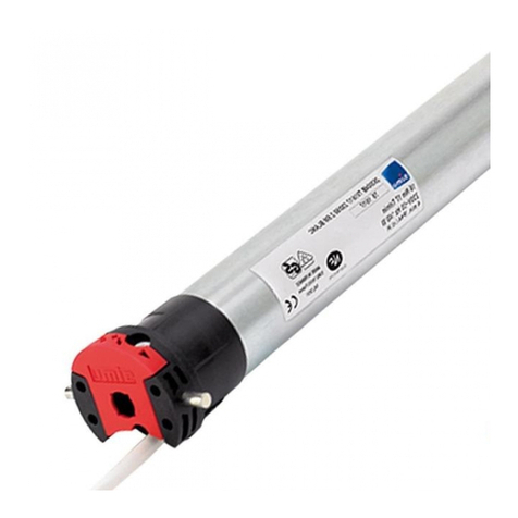
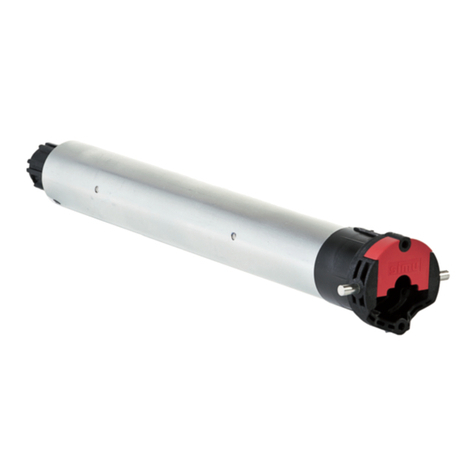
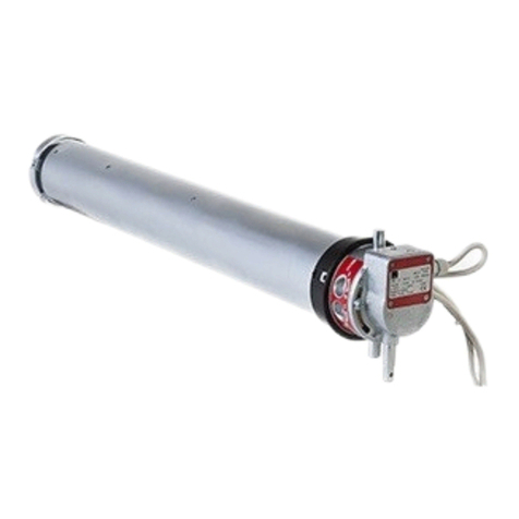
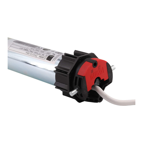
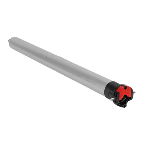
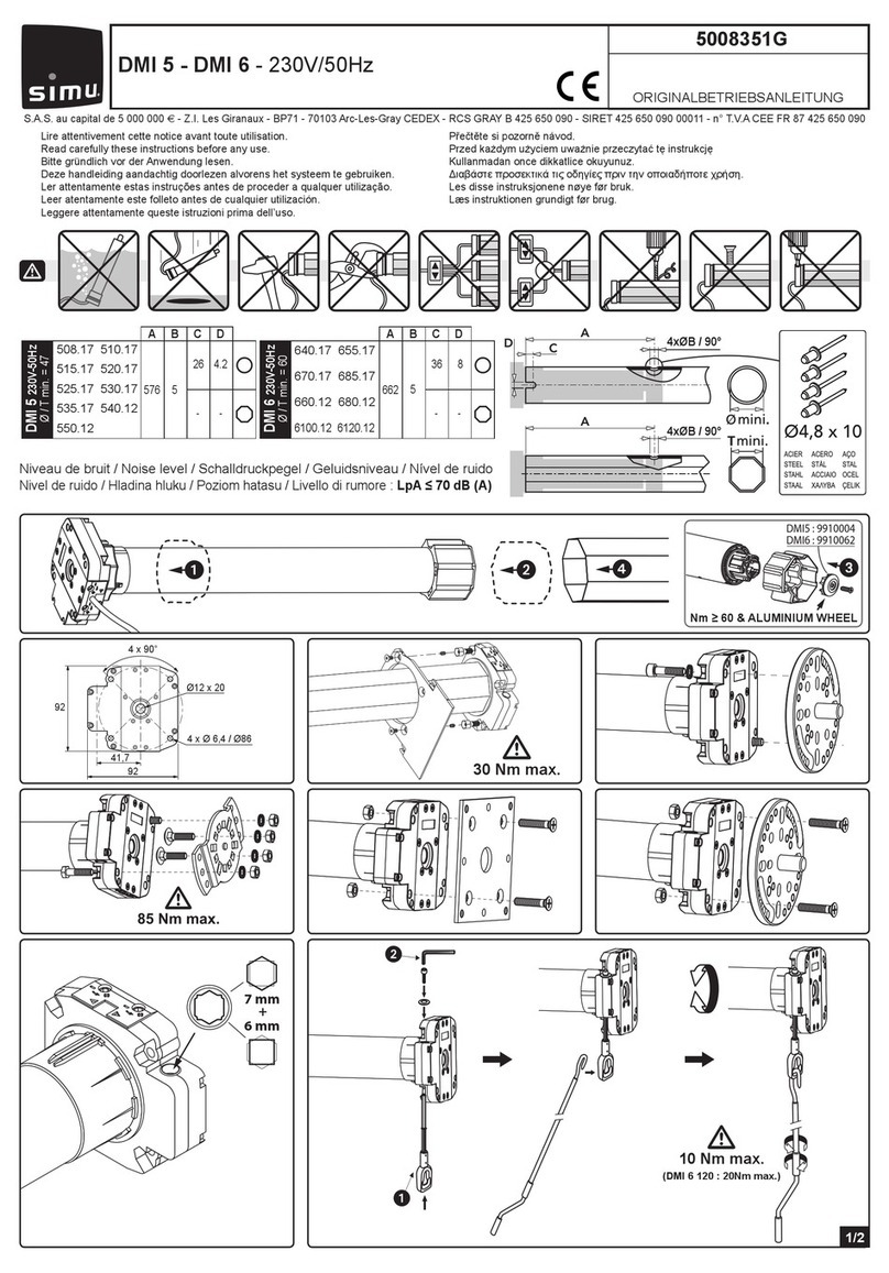
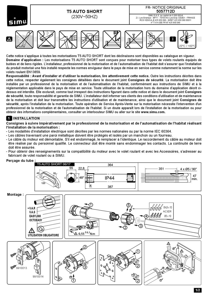
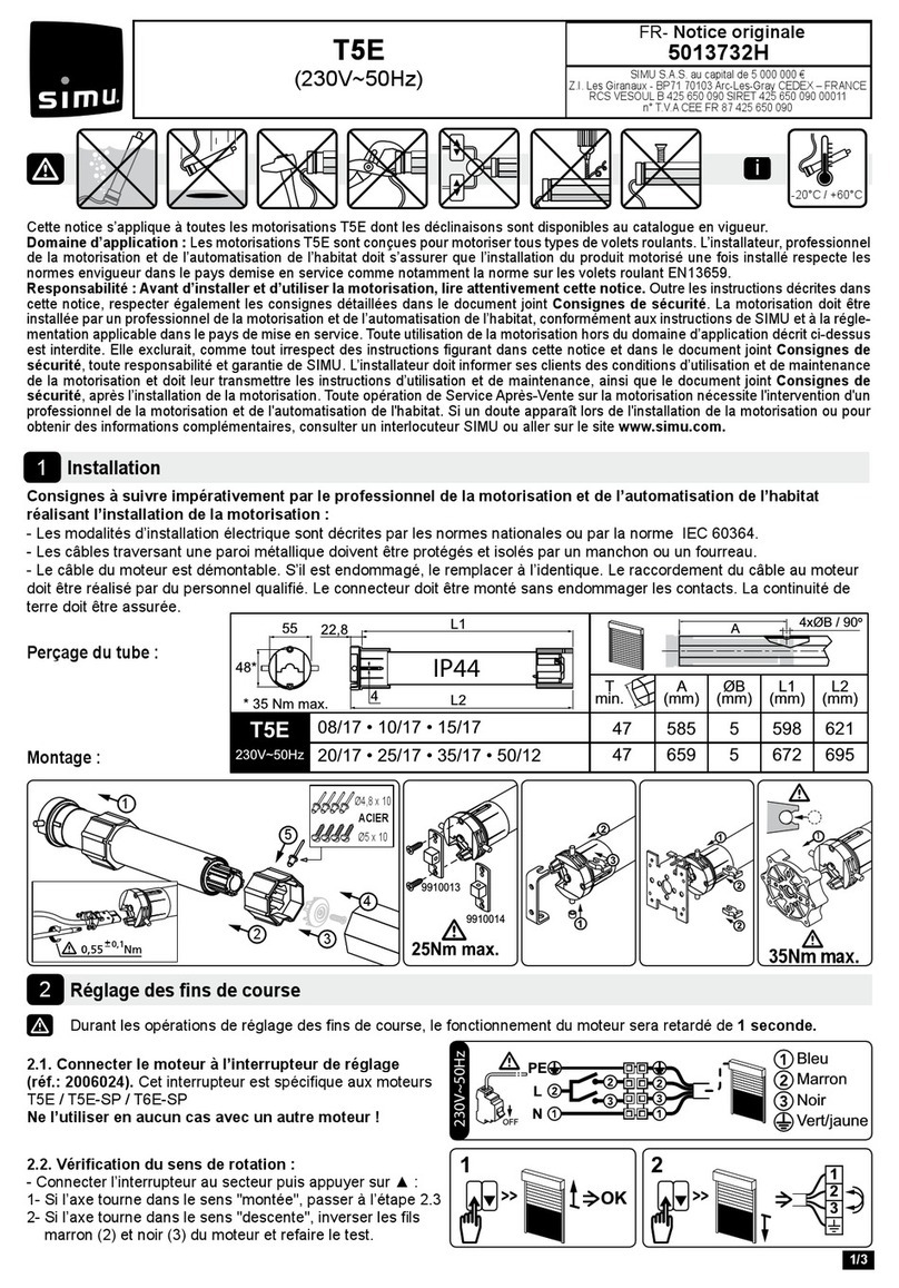
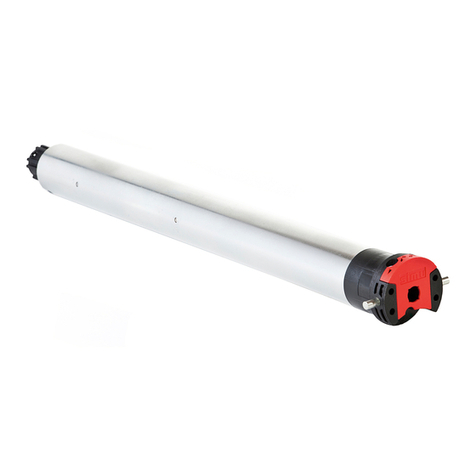
Simu T5E-SP Hz User manual

1/6
EN-Original instructions
5054093E
SIMU S.A.S. au capital de 5 000 000 €
Z.I. Les Giranaux - BP71 - 70103 Arc-Les-Gray CEDEX - FRANCE
RCS VESOUL B 425 650 090 - SIRET 425 650 090 00011
n° T.V.A CEE FR 87 425 650 090
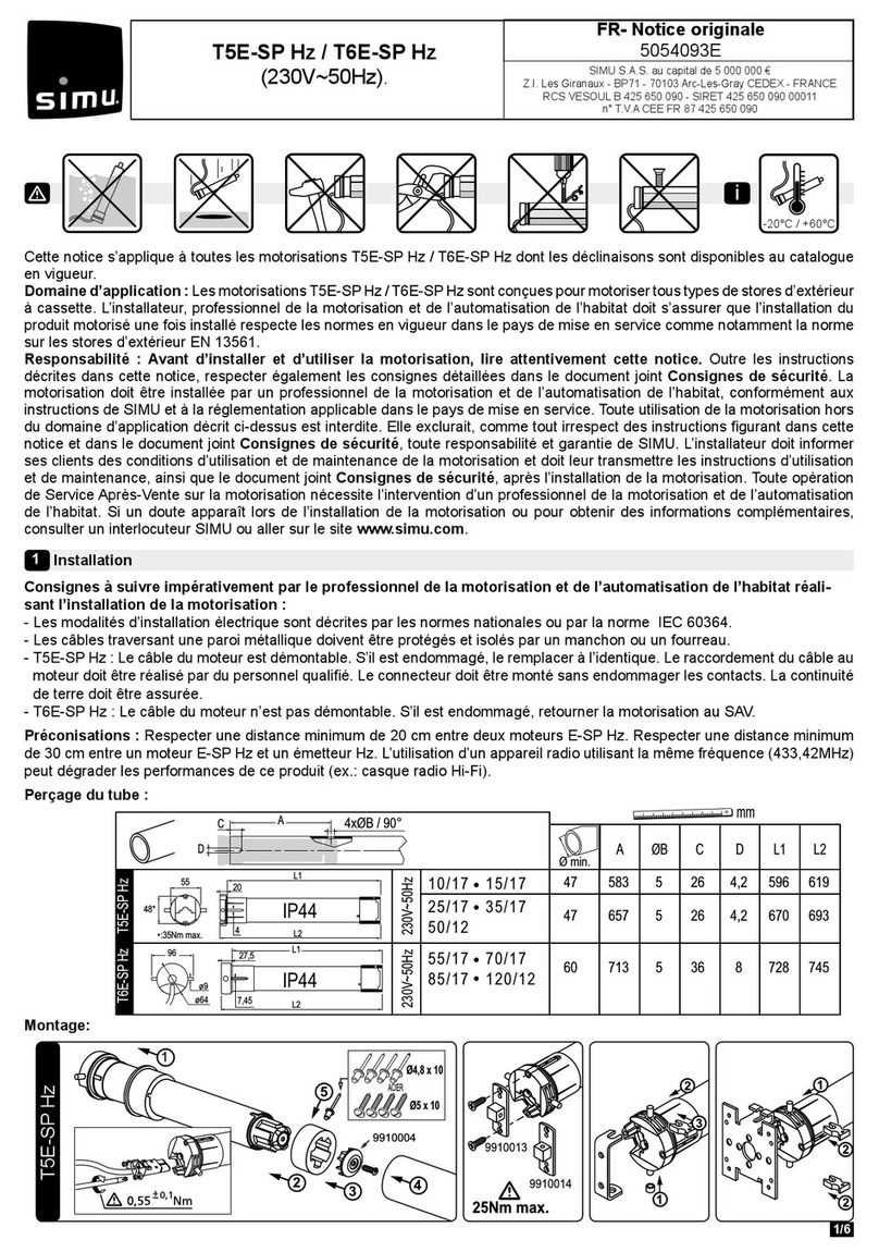
Instructions which must be followed by the drive and home automation professional installing the drive:
- Methods of wiring are given by national standards or IEC 60364 standard.
- Cables which pass through a metal wall must be protected and isolated using a sheath or sleeve.
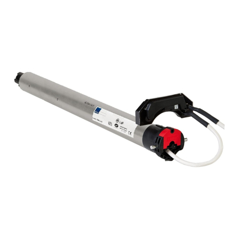
- T5E-SP Hz: The cable for the motor can be removed. If it is damaged, replace by the same. The cable may only be
connected to the motor by qualied personnel. The connector is to be assembled without damaging the contacts. The
continuity of the earth connection must be ensured.
- T6E-SP Hz: The cable for the motor cannot be removed. If it is damaged, return the drive to the After-Sales department.
Recommendations: Keep a minimum distance of 20 cm between two E-SP Hz motors. Keep a minimum distance of 30 cm
between E-SP Hz motors and Hz transmitters. A radio appliance using the same frequency (433,42 MHz) may deteriorate
our product’s performance (ex. : hi- radio headphones).
Drilling the tube:
These instructions apply to all T5E-SP Hz/T6E-SP Hz drive, the dierent versions of which are available in the current catalogue.
Field: The T5E-SP Hz/T6E-SP Hz drive are designed to drive all types of outdoor awnings with cassette. The installer, who
must be a motorisation and home automation professional, must ensure that the drive product is installed in accordance with the
standards in force in the country in which it is installed such as EN 13561 relating to outdoor screens and awnings.
Liability: Before installing and using the drive, please read operating and installation guide carefully. Please read
these instructions carefully before installing and using the drive. In addition to following the instructions given in this guide,
the instructions detailed in the attached Safety instructions document must also be observed. The drive must be installed by
a motorisation and home automation professional, according to instructions from SIMU and the regulations applicable in the
country in which it is commissioned. It is prohibited to use the drive outside the eld of application described above. Such use, and
any failure to comply with the instructions given in this guide and in the attached Safety instructions document, absolves SIMU
of any liability and invalidates the warranty. The installer must inform its customers of the operating and maintenance conditions
for the drive and must provide them with the instructions for use and maintenance, and the attached Safety instructions
document, after installing the drive. Any After-Sales Service operation on the drive must be performed by a motorisation and
home automation professional. If in doubt when installing the drive, or to obtain additional information, contact a SIMU adviser
or go to the website www.simu.com.
Installation
1
T5E-SP Hz / T6E-SP Hz
(230V~50Hz).
-20°C / +60°C
i
Ø min.
AØBC DL1L2
mm
L1
L2
4
20
55
48*
*:35Nm max.
96
ø64
ø9
L2
27,5 L1
A
C
D
4xØB / 90°
T5E-SP Hz
T6E-SP
Hz
230V~50Hz
230V~50H
z
60 713 5368728 745
47 657 526 4,2 670 693
47 583 526 4,2 596 619
7,45
25/17 35/17
50/12
10/17 15/17
55/17 70/17
85/17 120/12
IP44
IP44
Mounting:
23
5
4
Ø4,8 x 10
Ø5 x 10
STEEL
9910004
1
T5E-SP Hz

End-limit adjustement
4
Compatible transmitters
3
Wiring
2
2/6
1
24
3
T6E-SP Hz
2
3
5
4
STEEL
T5E-SP Hz : 9910004
T6E-SP Hz : 9910062
Nm ≥ 60 & ALUMINIUM WHEEL
PE
L
N
230V~50Hz
T5E-SP Hz / T6E-SP Hz
Blue
Brown
Green / yellow
You must have the possibility to switch o
individually each motor.
- Attach cables to prevent any contact with moving
parts.
- If the motor is used outdoors and if the power
supply cable is of the H05-VVF type, then run the
cable in a UV-resistant conduit, e.g. trunking.
(12 transmitters max./3 sensors max. for one motor)
1: 1/5 channels Wall Hz transmitters / Memory Hz
2: 1/5 channels / SUN Mobile Hz transmitters
3: Color Multi 16 / Timer Easy / Timer Multi transmitters
4: Windy Hz Accel
5: EOSUN Hz VS
Location of the PROG key on Hz transmitters:
Do not position the transmitter near metal in order to
avoid range losses.
If the installation includes several motors, only one motor is to be powered during this programming proce-
dure (4.1). It will eliminate interferences with the other motor during the procedure.
4.1- Learning mode:
- Switch the motor ON.
- Simultaneously press the “Up” and “Down” buttons of a Hz
transmitter. The motor will run for 0,5 second in one direction,
then in the other. The transmitter now controls the motor in
unstable mode, move to stage 4.2
4.2- Checking the rotation direction :
>>
ON
3s
aOK 4.3
OK 4.3
b
>>
>>
>> >>
>>
>> >>
Press the “Up” button of the transmitter:
a- If the motorized tube runs in the up direction, move to next stage (4.3).
b- If the motorized tube runs in the down direction, reverse the rotation direction by pressing the “Stop” button for at
least 3 seconds. The motor will run for 0,5 second in one direction, then in the other direction. Move to the stage 4.3.
2 3
3
4
4
5
5
1

3/6
Programming the rst individual control point
5
Programming a new (individual, group or general) control point
6
This operation can only be performed from the transmitter that was used for operation 4.1.
- Press the transmitter “PROG“ Key for approximately one second. The
motor will run for 0,5 second in one direction and then in the other.
Your transmitter is now programmed to control the motor in stable mode.
PROG 1s.
1
>>
6.1- Open the memory of the motor from the control transmitter:
- Press the “PROG” key of the transmitter for about 3 seconds. The motor
will run for 0,5 second in one direction and then in the other.
6.2- Conrm the operation from the new transmitter you want to
program:
- Press the “PROG” key of the transmitter for 1 second. The motor will run
for 0,5 second in one direction and then in the other.
PROG ≥ 3s.
1
2
>>
PROG ≤ 1s.
1
2
>>
- For group controls, repeat operations 6.1 and 6.2 for each motor in the group.
- For general controls, repeat operations 6.1 and 6.2 for each motor in the installation.
- To delete an transmitter from the memory of a motor, perform operations 6.1 with a programmed transmitter, then perform the operation 6.2
with the transmitter to be deleted.
4.3- Adjustment of the down end limit:
With the T5E-SP Hz / T6E-SP Hz motor, there is no adjustment of the up end limit.
i
1 2 3
2s
4
1- Move the motor to the wished down end limit position using the “Down” and “Up” buttons.
2- To memorize the Down end limit position, press simultaneously the “Stop” and “Up” buttons. The motor will run
automatically in the up direction.
3- Before the motor reaches the Up end limit, press the “Stop” button.
4- Press 2s on the “Stop” button to conrm the adjustments. The motor will stop and will run for 0,5 second in one direc-
tion and then in the other. The operation is completed. Go to step 5.
If you do not want to use this transmitter as the individual control:
- cut the power supply (2 seconds minimum).
- repeat the operation 4.1* with a new transmitter and then go to step §5.
* In this case, the motor will run for 0,5 second in both directions, that means the limits setting is already done.

4/6
« Closing force » function
8
1- Position the motor to the halfway position using the “Down” or “Up” button. Press the “Stop” button to stop the awning.
2- To activate closing force function press twice successively:
- 1st press: For half a second press simultaneously “Stop” and “Up” buttons, without the motor rotating.
- 2nd press: For more than 3 seconds press simultaneously “Stop” and “Up” buttons, until the motor jogs.
The motor is now in programming mode for only 10 seconds, the motor is factory set at the medium level.
3- To increase the closing force, press the “Up” button until the awning makes a slow movement, the cassette awning’s
closing force has moved up a level.
- To decrease the closing force, press the “Down” button until the awning makes a slow movement, the cassette
awning’s closing force has moved down a level.
4- Conrm the new setting by pressing 2 seconds the “Stop” button, until the motor jogs. The new setting is memorized.
This function allows the closing force of the awning cassette to be increased or decreased to 3 levels high-medium-low.
Contact the awning’s manufacturer before using these functions to check the compatibility of your systems.
For safety reasons, this function can only be accessed via the individual control point in 3 situations:
- After the settings conrmation and before programming the rst control point.
- After programming the rst control and during the next 4 cycles.
- After a single power outage and during the next 4 cycles.
2s.
3s.
+
0,5s.
1- 2- 3- 4-
Recommendations when using a sensor: If the Wind sensor on an installation is changed or deleted, it is important to
delete it from the memory of all the motors in which it was programmed.
Programming a sensor
7
7.1- Open the memory of the motor from the individual control
transmitter:
- Press the “PROG” key of the transmitter for about 3 seconds. The motor
will run for 0,5 second in one direction and then in the other.
7.2- Conrm the operation from the sensor you wish to add :
- Press the “PROG” key of the sensor less than 1 second. The motor will
run for 0,5 second in one direction and then in the other.
PROG ≥ 3s.
1
2
>>
PROG ≤ 1s.
1
2
>>
- For group controls, repeat operations 7,1 and 7,2 for each motor in the group.
- To delete a sensor from the motor’s memory: Perform operation 7.1 from the individual control transmitter and operation
7.2 from the automatic control to be deleted.
i
i

5/6
This function allows you to tighten the fabric each time the awning is lowered. To activate the function set the angle
between 11 and 180°. To disable the Back impulse, set the angle to 0°.
1- Move the motor to the Down end limit previously adjusted in §4.3 with the “Down” button.
2- Press simultaneously for 5 seconds the “Up” and “Stop” buttons, The motor will run for 0,5 second in one direction and
then in the other direction.
3- Adjust the angle of back impulse function (between 11 and 180°) with the “Up” and “Down” buttons.
4- Press 2s on the “Stop” button to conrm the adjustments. The motor will stop and will run for 0,5 second in one direction
and then in the other. The operation is completed.
“Back impulse” function
9
The «back inpulse» function is disable in the factory mode.
5s. 2s.
between 11° and 180°
1- 2- 3- 4-
This function enables the release of the fabric tension after the complete closing of the box awning.
For safety reasons, this function can only be activated or deactivated by the individual control point in 3 situations:
- After the settings conrmation and before programming the rst control point.
- After programming the rst control point and during the next 4 cycles.
- After a single power outage and during the next 4 cycles.
To activate or deactivate this function, the procedure is the same:
1- Retract the awning using the Up button.
2- Press simultaneously the Stop and Down buttons for 5 seconds. The
motor will stop and will run for 0,5 second in one direction and then in the
other. The operation is completed.
“Back release” function for casette awning.
10
Recording / controling / deleting intermediate position
11
5s.
The «back release» function is disable in the factory mode.
2s.
5s.
1- 2- 3- 4-
Re-adjustement of the down end limits
12
1- Move the motor to the down end limit previously set in §4.3 with the “Down” button.
2- Press simultaneously for 5 seconds the “Up” and “Down” buttons, the motor will run for a half a second in one direction
and then in the other direction.
3- Adjust the new position with the “Up” and “Down” buttons.
4- Conrm the new position by pressing 2 seconds the “Stop” button. The motor will run for a half a second in one direction
and then in the other direction. The new end limits setting is memorized.
1- 2-
5 s.
Recording:
- Move the motor to the wanted
position.
- Press 5 seconds on the “Stop”
button. The motor will run for 0,5
second in one direction and then in
the other.
0,5 s.
Control:
- Press the “Stop” button for
0,5 second. The motor runs
to the intermediate position.
Deleting :
- Position the motor on the intermediate position. Press 5 seconds on the “Stop” button, the intermediate position is deleted.
With the T5E-SP Hz / T6E-SP Hz motor, there is no re-adjustment of the up limit.
i
i
i
i
i

6/6
13.1 - Switch o the power supply to the motor for 2 seconds.
13.2 - Switch the power to the motor back on for 7 seconds.
13.3 - Switch o the power supply to the motor for 2 seconds.
13.4 - Switch the power to the motor back on.
If the motor is on the end limit position (up or down), the motor will run
briey on one direction and then in the other, otherwise, the motor runs
for 5 seconds in random direction.
13.5- Then, conrm the cancelling of the concerned motor
from the individual control:
- Press the “PROG” key of the transmitter more than 7
seconds. Maintain the pressure until the motor will rst run for
a half a second in one direction and then the other, and a few
second later, it will run again in both direction.
Cancelling programming
13
If you switch on/o the power to several motors, they will all be in the cancellation mode. That is why you must
eject out of this mode all the motors that are not to be deleted by sending a command from their individual control
transmitter (UP and DOWN).
5s.
OFF
2s 7s 2s
ON ONOFF
13.1 13.2 13.3 13.4
2s. 7s.
PROG > 7s.
>>
1
Operation and maintenance
14
The receiver is back in its original conguration. No more transmitters are programmed in the memory, start programming
again from section §4.1.The setting of functions « Back impulse», « Back release », « Closing force » are kept.
The motor is now in the “cancelling” mode.
- This drive is maintenance-free.
- Press the ▲ button on the control point to raise the motorised product.
- Press the ▼ button on the control point to lower the motorised product.
- If the motorised product is moving, briey press the “Stop” button, the motorised product stop automatically.
- The motorised product is then stopped, briey press the “Stop” button, the motorised product moves to the programmed
intermediate position. (To modify or delete an intermediate position, see the section §11).
Tips and recommendations for use:
If the motorised product still does not work, contact a drive and home automation professional.
SIMU SAS, F-70103 as manufacturer hereby declares that the drive covered by these instructions when marked for input voltage 230V~50Hz and used
as intended according to these instructions, is in compliance with the essential requirements of the applicable European Directives and in particular of
the Machinery Directive 2006/42/EC, and the Radio Directive 2014/53/EU. The full text of the EU declaration of conformity is available at www.simu.
com. Emmanuel CARMIER, general director, GRAY, 01/2017.
PROBLEMS
The motorized product does not operate
POSSIBLES CAUSES
The overheating protection on the drive has been
activated
SOLUTIONS
Wait for the drive to cool down.
i
Other manuals for T5E-SP Hz
1
This manual suits for next models
1
Table of contents
Other Simu DC Drive manuals

