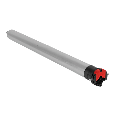
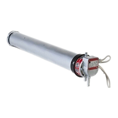
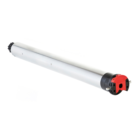
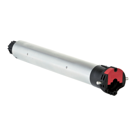
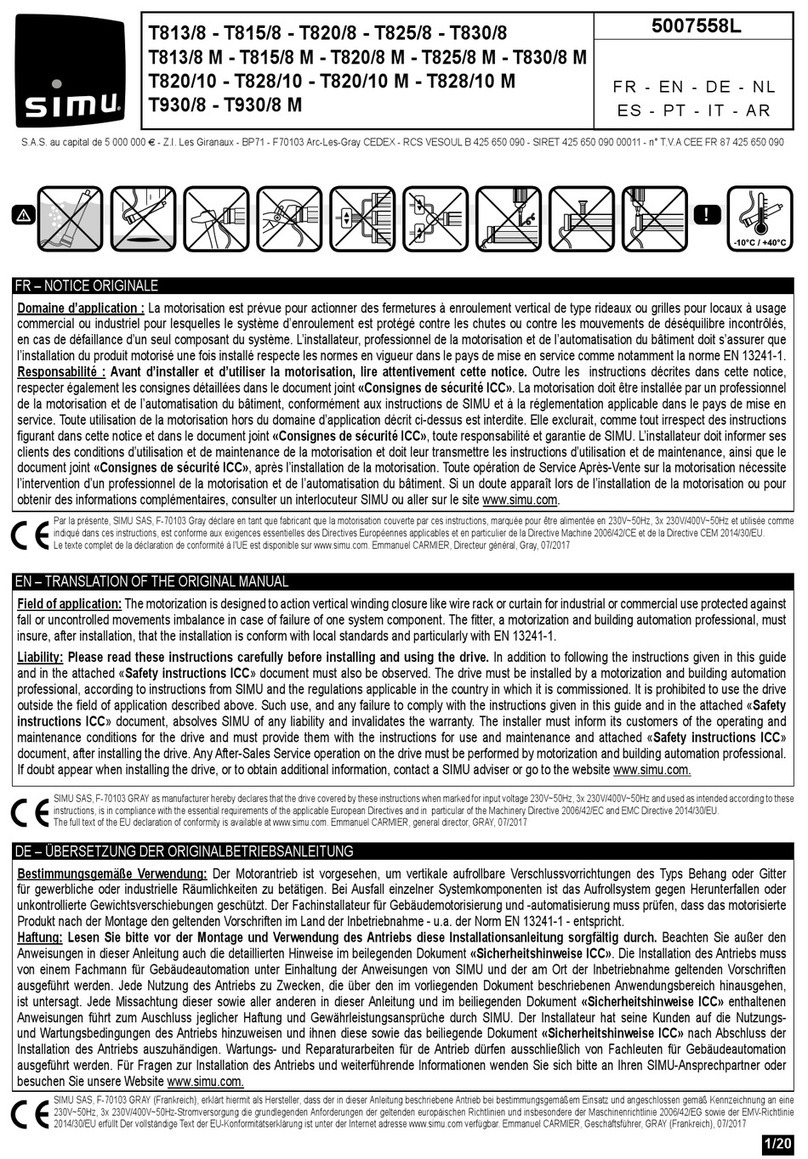
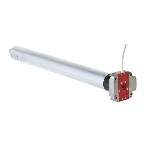
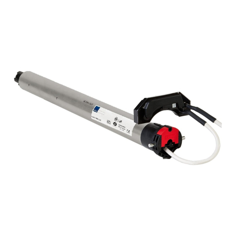
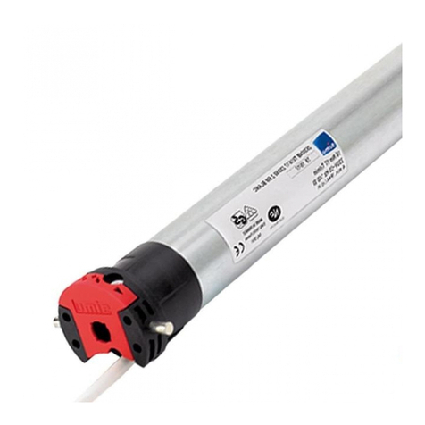
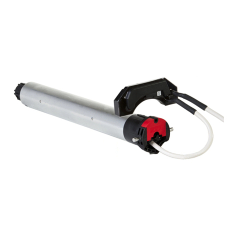
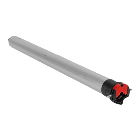
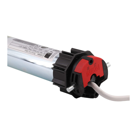
Simu T5E-SP Hz User manual

1/6
FR- Notice originale
5054093E
SIMU S.A.S. au capital de 5 000 000 €
Z.I. Les Giranaux - BP71 - 70103 Arc-Les-Gray CEDEX - FRANCE
RCS VESOUL B 425 650 090 - SIRET 425 650 090 00011
n° T.V.A CEE FR 87 425 650 090
Consignes à suivre impérativement par le professionnel de la motorisation et de l’automatisation de l’habitat réali-
sant l’installation de la motorisation :
- Les modalités d’installation électrique sont décrites par les normes nationales ou par la norme IEC 60364.
- Les câbles traversant une paroi métallique doivent être protégés et isolés par un manchon ou un fourreau.
- T5E-SP Hz : Le câble du moteur est démontable. S’il est endommagé, le remplacer à l’identique. Le raccordement du câble au
moteur doit être réalisé par du personnel qualié. Le connecteur doit être monté sans endommager les contacts. La continuité
de terre doit être assurée.
- T6E-SP Hz : Le câble du moteur n’est pas démontable. S’il est endommagé, retourner la motorisation au SAV.
Préconisations : Respecter une distance minimum de 20 cm entre deux moteurs E-SP Hz. Respecter une distance minimum
de 30 cm entre un moteur E-SP Hz et un émetteur Hz. L’utilisation d’un appareil radio utilisant la même fréquence (433,42MHz)
peut dégrader les performances de ce produit (ex.: casque radio Hi-Fi).
Perçage du tube :
Cette notice s’applique à toutes les motorisations T5E-SP Hz / T6E-SP Hz dont les déclinaisons sont disponibles au catalogue
en vigueur.
Domaine d’application : Les motorisations T5E-SP Hz / T6E-SP Hz sont conçues pour motoriser tous types de stores d’extérieur
à cassette. L’installateur, professionnel de la motorisation et de l’automatisation de l’habitat doit s’assurer que l’installation du
produit motorisé une fois installé respecte les normes en vigueur dans le pays de mise en service comme notamment la norme
sur les stores d’extérieur EN 13561.
Responsabilité : Avant d’installer et d’utiliser la motorisation, lire attentivement cette notice. Outre les instructions
décrites dans cette notice, respecter également les consignes détaillées dans le document joint Consignes de sécurité. La
motorisation doit être installée par un professionnel de la motorisation et de l’automatisation de l’habitat, conformément aux
instructions de SIMU et à la réglementation applicable dans le pays de mise en service. Toute utilisation de la motorisation hors
du domaine d’application décrit ci-dessus est interdite. Elle exclurait, comme tout irrespect des instructions gurant dans cette
notice et dans le document joint Consignes de sécurité, toute responsabilité et garantie de SIMU. L’installateur doit informer
ses clients des conditions d’utilisation et de maintenance de la motorisation et doit leur transmettre les instructions d’utilisation
et de maintenance, ainsi que le document joint Consignes de sécurité, après l’installation de la motorisation. Toute opération
de Service Après-Vente sur la motorisation nécessite l’intervention d’un professionnel de la motorisation et de l’automatisation
de l’habitat. Si un doute apparaît lors de l’installation de la motorisation ou pour obtenir des informations complémentaires,
consulter un interlocuteur SIMU ou aller sur le site www.simu.com.
Installation
1
T5E-SP Hz / T6E-SP Hz
(230V~50Hz).
-20°C / +60°C
i
Ø min.
AØBC DL1L2
mm
L1
L2
4
20
55
48*
*:35Nm max.
96
ø64
ø9
L2
27,5 L1
A
C
D
4xØB / 90°
T5E-SP Hz
T6E-SP
Hz
230V~50Hz
230V~50H
z
60 713 5368728 745
47 657 526 4,2 670 693
47 583 526 4,2 596 619
7,45
25/17 35/17
50/12
10/17 15/17
55/17 70/17
85/17 120/12
IP44
IP44
Montage:
23
5
4
Ø4,8 x 10
Ø5 x 10
ACIER
9910004
1
T5E-SP Hz

Réglage des ns de course
4
Emetteurs compatibles
3
Câblage
2
2/6
1
24
3
T6E-SP Hz
2
3
5
4
T5E-SP Hz : 9910004
T6E-SP Hz : 9910062
Nm ≥ 60 & ALUMINIUM WHEEL
PE
L
N
230V~50Hz
T5E-SP Hz / T6E-SP Hz
Bleu
Marron
Vert / jaune
Il est recommandé de pouvoir couper
individuellement l’alimentation de chaque
moteur.
- Attacher les câbles pour éviter tout contact avec
une partie en mouvement.
- Si la motorisation est utilisée en extérieur, et si le
câble d’alimentation est de type H05-VVF alors
installer le câble dans un conduit résistant aux UV,
par exemple sous goulotte.
(12 émetteurs max. / 3 capteurs max. par moteur)
1 : Emetteur Hz mural 1 / 5 canaux / Memory Hz
2 : Emetteur Hz mobile 1 / 5 canaux / SUN
3 : Emetteur Hz Color Multi / Timer Easy / Timer Multi
4 : Windy Hz Accel
5 : Capteur EOSUN Hz VS
Emplacement de la touche PROG sur les émetteurs Hz :
Éloigner les émetteurs de toute surface ou structure
métallique qui pourraient nuire à leur bon fonctionnement
(perte de portée).
Si l’installation comporte plusieurs moteurs, un seul moteur doit être alimenté pendant les opérations du
chapitre 4.1, ceci pour éviter les interférences avec les autres moteurs lors de la programmation.
4.1- Mode apprentissage :
- Mettre le moteur sous tension.
- Appuyer simultanément sur les touches «Montée» et
«Descente» d’un émetteur Hz. Le moteur eectue une rotation
de 0,5 seconde dans un sens puis dans l’autre.
Cet émetteur commande maintenant le moteur en mode instable.
Passer à l’étape 4.2.
4.2- Conguration du sens de rotation:
>>
ON
3s
aOK 4.3
OK 4.3
b
>>
>>
>> >>
>>
>> >>
Appuyer sur la touche «Montée» de l’émetteur :
a- Si l’axe tourne dans le sens montée, passer à l’étape 4.3.
b- Si l’axe tourne dans le sens descente, inverser le sens de rotation en appuyant sur la touche «Stop» pendant au
moins 3 secondes. Le moteur conrme la modication par une rotation de 0,5 seconde dans un sens puis dans l’autre.
Passer à l’étape 4.3.
2 3
3
4
4
5
5
1

3/6
Programmation du premier point de commande individuelle
5
Programmation d’un nouveau point de commande (individuelle, groupe ou générale)
6
Cette opération ne peut être eectuée que depuis l’émetteur ayant eectué l’opération 4.1.
- Appuyer environ 1 seconde sur la touche «PROG» de l’émetteur.
Le moteur eectue une rotation de 0,5 seconde dans un sens puis dans
l’autre.
Votre émetteur est maintenant programmé et commande le moteur en mode
stable.
PROG 1s.
1
>>
6.1- Ouvrir la mémoire du moteur depuis l’émetteur de commande
individuelle :
- Appuyer environ 3 secondes sur la touche «PROG» de l’émetteur.
Le moteur eectue une rotation de 0,5 seconde dans un sens puis dans
l’autre.
6.2- Valider l’opération depuis le nouvel émetteur à programmer :
- Appuyer environ 1 seconde sur la touche «PROG» du nouvel émetteur.
Le moteur eectue une rotation de 0,5 seconde dans un sens puis dans
l’autre.
PROG ≥ 3s.
1
2
>>
PROG ≤ 1s.
1
2
>>
- Si votre nouveau point de commande est une commande de groupe : répéter les opérations 6.1 et 6.2 pour chaque moteur du groupe.
- Si votre nouveau point de commande est une commande générale : répéter les opérations 6.1 et 6.2 pour chaque moteur de l’installation.
- Pour supprimer un émetteur de la mémoire du moteur : Eectuer les opérations 6.1 depuis l’émetteur de commande individuelle et
l’opération 6.2 depuis l’émetteur à supprimer.
4.3- Réglage du n de course bas :
Avec le moteur T5E-SP Hz / T6E-SP Hz, il n’y a pas de réglage du n de course haut.
i
1 2 3
2s
4
1- Positionner le moteur sur le point d’arrêt bas souhaité à l’aide des touches «Montée» et «Descente».
2- Appuyer simultanément sur les touches «Stop» et «Montée» pour mémoriser le point d’arrêt bas.
Le moteur se met automatiquement en rotation en montée.
3- Appuyer sur «Stop» pour immobiliser le moteur.
4- Appuyer 2s sur la touche «Stop» pour valider le réglage. Le moteur eectue une rotation de 0,5 seconde dans un sens
puis dans l’autre. L’opération est terminée. Passer à l’étape 5.
Si vous souhaitez programmer un autre émetteur que celui utilisé jusqu’à présent comme point de commande du moteur :
- couper l’alimentation du moteur (2 secondes minimum).
- reprendre l’opération 4.1* avec un nouvel émetteur avant de passer au chapitre 5.
* A la mise sous tension le moteur eectue une courte rotation dans un sens puis dans l’autre, ce qui indique que les ns de
course sont déjà réglés.

4/6
Fonction « Eort de fermeture » pour store cassette.
8
1- Placer le store en position médiane à l’aide des touches «Montée» et «Descente». Appuyer sur « Stop » pour immobiliser
le moteur.
2- Pour mettre en œuvre cette fonction, faire 2 appuis successifs :
1er appui : Faire un appui bref et simultané sur les touches «Stop» et «Montée» sans obtenir de rotation du moteur.
2ème appui : appui maintenu et simultané (> 3s) sur les touches «Stop» et «Montée», jusqu’aux mouvements du store.
Le moteur est en mode programmation pendant 10s uniquement. Par défaut, le moteur est positionné en sortie d’usine
sur le niveau moyen.
3- Pour augmenter l’eort de fermeture, appuyer sur la touche «Montée» jusqu’au mouvement lent du store : l’eort de
fermeture du store cassette est passé au seuil supérieur.
- Pour diminuer l’eort de fermeture, appuyer sur la touche «Descente» jusqu’au mouvement lent du store : l’eort de fermeture
du store cassette est passé au seuil inférieur.
4- Appuyer 2 secondes sur la touche «Stop» pour valider le réglage. Le moteur eectue une rotation de 0,5 seconde dans un
sens puis dans l’autre. Le nouvel eort de fermeture est enregistré.
Cette fonction permet d’augmenter ou de diminuer l’eort de fermeture de la cassette du store sur 3 seuils (fort-moyen-faible).
Contacter le fabricant du store avant toute utilisation de ces fonctions pour valider la compatibilité de votre
installation. Par sécurité, cette fonction est atteignable par le point de commande dans 3 cas seulement :
- Après la validation des réglages et avant l’enregistrement du premier point de commande.
- Après l’enregistrement du premier point de commande et durant les 4 cycles suivants.
- Après une simple coupure d’alimentation et durant les 4 cycles suivants.
2s.
3s.
+
0,5s.
1- 2- 3- 4-
Préconisations concernant l’emploi d’un automatisme : En cas d’échange ou de suppression de l’automatisme, il est
impératif de le supprimer de la mémoire de tous les moteurs dans lesquels il était programmé.
Programmation d’un automatisme
7
7.1- Ouvrir la mémoire du moteur depuis l’émetteur de commande
individuelle:
- Appuyer environ 3 secondes sur la touche «PROG» de l’émetteur.
Le moteur eectue une rotation de 0,5 seconde dans un sens puis dans
l’autre.
7.2- Valider l’opération depuis l’automatisme à programmer :
- Appuyer environ 1 seconde sur la touche «PROG» de l’automatisme.
Le moteur eectue une rotation de 0,5 seconde dans un sens puis dans
l’autre.
PROG ≥ 3s.
1
2
>>
PROG ≤ 1s.
1
2
>>
- Si votre automatisme doit contrôler un groupe de moteur : Répéter les opérations 7.1 et 7.2 pour chaque moteur du groupe.
- Pour supprimer l’automatisme de la mémoire du moteur : Eectuer l’opération 7.1 depuis l’émetteur de commande
individuelle et l’opération 7.2 depuis l’automatisme à supprimer.
i
i

5/6
Cette fonction permet de tendre la toile après chaque mouvement d’ouverture du store . Pour activer cette fonction, régler
l’angle de tension de la toile entre 11 et 180°. Pour désactiver cette fonction régler l’angle à 0 °.
1- Positionner le moteur sur le point d’arrêt bas réglé en §4.3 à l’aide de la touche descente.
2- Appuyer simultanément sur les touches «Stop» et «Montée» pendant 5 secondes. Le moteur eectue une rotation de 0,5
seconde dans un sens puis dans l’autre.
3- Ajuster la tension de la toile à l’aide des touches «Montée» ou «Descente» (entre 11 et 180°).
4- Appuyer 2s sur la touche «Stop» pour valider le réglage. Le moteur eectue une rotation de 0,5 seconde dans un sens puis
dans l’autre. L’opération est terminée.
Fonction “Back impulse”
9
Par défaut, la fonction « Back impulse » est désactivée.
5s. 2s.
entre 11° et 180°
1- 2- 3- 4-
Cette fonction permet de relâcher la tension sur la toile après la fermeture du store cassette.
Par sécurité, cette fonction peut être activée ou désactivée par le point de commande dans 3 cas seulement :
- Après la validation des réglages et avant l’enregistrement du premier point de commande
- Après l’enregistrement du premier point de commande et durant les 4 cycles suivants.
- Après une simple coupure d’alimentation et durant les 4 cycles suivants.
Pour activer ou désactiver la fonction « Back release », la procédure est identique:
1- Positionner le moteur sur le point d’arrêt haut réglé en §4.3 à l’aide de la touche « Montée ».
2- Appuyer simultanément sur les touches «Stop» et «Descente» pendant
5 secondes. Le moteur eectue une rotation de 0,5 seconde dans un
sens puis dans l’autre. L’opération est terminée
Fonction « Back release » pour stores cassette
10
Enregistrement / commande / suppression de la position intermédiaire
11
5s.
Par défaut, la fonction « Back release » est désactivée.
2s.
5s.
1- 2- 3- 4-
Ré-ajustement du n de course bas
12
1- Positionner le moteur sur le point d’arrêt bas réglé en §4.3 à l’aide de la touche «Descente».
2- Appuyer simultanément sur les touches «Montée» et «Descente» pendant 5 secondes. Le moteur eectue une rotation de
0,5 seconde dans un sens puis dans l’autre.
3- Aner le réglage à l’aide des touches «Descente» et «Montée» pour obtenir la position de n de course souhaitée.
4- Appuyer 2 secondes sur la touche «Stop». Le moteur eectue une rotation de 0,5 seconde dans un sens puis dans l’autre.
La nouvelle position de n de course est mémorisée.
1- 2-
5 s.
Enregistrement :
- Positionner le moteur sur la position
intermédiaire désirée.
- Appuyer 5 s. sur la touche «Stop».
Le moteur eectue une rotation de
0,5s dans un sens puis dans l’autre.
0,5 s.
Commande :
- Appuyer sur la touche
«Stop» pendant 0,5 s.
Le moteur rejoint la
position intermédiaire.
Suppression : Positionner le moteur sur la position intermédiaire. Appuyer 5s. sur la touche «Stop». La position intermé-
diaire est supprimée.
Avec le moteur T5E-SP Hz / T6E-SP Hz, il n’y a pas de ré-ajustement du n de course haut.
i
i
i
i
i

6/6
13.1- Couper l’alimentation du moteur pendant 2 secondes.
13.2- Rétablir l’alimentation du moteur pendant 7 secondes.
13.3- Couper l’alimentation du moteur pendant 2 secondes.
13.4- Rétablir l’alimentation du moteur.
Si le moteur se trouve en position de n de course (haute ou basse),
il eectue une brève rotation dans les deux sens. Si le moteur se trouve
dans une autre position, il eectue une rotation de 5 secondes dans un
sens quelconque.
13.5- Ensuite valider l’annulation de la programmation
du moteur concerné depuis l’émetteur de commande
individuelle :
- Appuyer plus de 7 secondes sur la touche PROG de
l’émetteur. Maintenir l’appui jusqu’à ce que le moteur eectue
une première rotation de 0,5 seconde dans un sens puis dans
l’autre, puis quelques secondes plus tard une seconde rotation
de 0,5 seconde dans les deux sens.
Annulation de la programmation
13
Si vous intervenez sur l’alimentation de plusieurs moteurs, ils seront tous dans ce mode. Il convient donc
« d’éjecter » de ce mode tous les moteurs non concernés par cette modication en appuyant sur une touche de
commande d’un émetteur programmé.
5s.
OFF
2s 7s 2s
ON ONOFF
13.1 13.2 13.3 13.4
2s. 7s.
PROG > 7s.
>>
1
Utilisation et maintenance
14
Le moteur se retrouve dans sa conguration d’origine. Plus aucun émetteur n’est programmé en mémoire, reprendre la
programmation au chapitre §4.1. Le réglage des fonctions « Back impulse », « Back release », « Eort de fermeture »,
est conservé.
Le moteur est maintenant en mode « annulation de la programmation ».
- Cette motorisation ne nécessite pas d’opération de maintenance.
- Appuyer sur la touche ▲du point de commande pour faire monter le produit motorisé.
- Appuyer sur la touche ▼ du point de commande pour faire descendre le produit motorisé.
- Quand le produit motorisé est en cours de mouvement, un appui bref sur la touche « Stop » arrête le produit motorisé.
- Quand le produit motorisé est à l’arrêt, un appui bref sur la touche « Stop » commande le produit motorisé sur la position
intermédiaire programmée. (Pour modier ou supprimer une position intermédiaire voir le chapitre §11).
Astuces et conseils d’utilisation :
Si le produit motorisé ne fonctionne toujours pas, contacter un professionnel de la motorisation et de l’automatisation de
l’habitat.
Par la présente, SIMU SAS, F-70103 GRAY déclare en tant que fabricant que la motorisation couverte par ces instructions, marquée pour être alimen-
tée en 230V~50Hz et utilisée comme indiqué dans ces instructions, est conforme aux exigences essentielles des Directives Européennes applicables
et en particulier de la Directive Machine 2006/42/EC et de la Directive Radio 2014/53/EU. Le texte complet de la déclaration de conformité à l’UE est
disponible sur www.simu.com. Emmanuel CARMIER, directeur général, GRAY, 01/2017
CONSTATS
Le produit motorisé ne fonctionne pas
CAUSES POSSIBLES
La motorisation est en protection thermique
SOLUTIONS
Attendre que le moteur refroidisse
i

1/6
EN-Original instructions
5054093E
SIMU S.A.S. au capital de 5 000 000 €
Z.I. Les Giranaux - BP71 - 70103 Arc-Les-Gray CEDEX - FRANCE
RCS VESOUL B 425 650 090 - SIRET 425 650 090 00011
n° T.V.A CEE FR 87 425 650 090
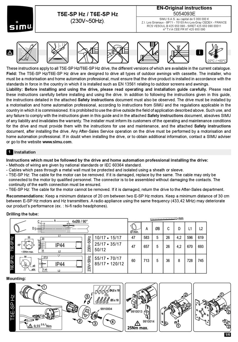
Instructions which must be followed by the drive and home automation professional installing the drive:
- Methods of wiring are given by national standards or IEC 60364 standard.
- Cables which pass through a metal wall must be protected and isolated using a sheath or sleeve.
- T5E-SP Hz: The cable for the motor can be removed. If it is damaged, replace by the same. The cable may only be
connected to the motor by qualied personnel. The connector is to be assembled without damaging the contacts. The
continuity of the earth connection must be ensured.
- T6E-SP Hz: The cable for the motor cannot be removed. If it is damaged, return the drive to the After-Sales department.
Recommendations: Keep a minimum distance of 20 cm between two E-SP Hz motors. Keep a minimum distance of 30 cm
between E-SP Hz motors and Hz transmitters. A radio appliance using the same frequency (433,42 MHz) may deteriorate
our product’s performance (ex. : hi- radio headphones).
Drilling the tube:
These instructions apply to all T5E-SP Hz/T6E-SP Hz drive, the dierent versions of which are available in the current catalogue.
Field: The T5E-SP Hz/T6E-SP Hz drive are designed to drive all types of outdoor awnings with cassette. The installer, who
must be a motorisation and home automation professional, must ensure that the drive product is installed in accordance with the
standards in force in the country in which it is installed such as EN 13561 relating to outdoor screens and awnings.
Liability: Before installing and using the drive, please read operating and installation guide carefully. Please read
these instructions carefully before installing and using the drive. In addition to following the instructions given in this guide,
the instructions detailed in the attached Safety instructions document must also be observed. The drive must be installed by
a motorisation and home automation professional, according to instructions from SIMU and the regulations applicable in the
country in which it is commissioned. It is prohibited to use the drive outside the eld of application described above. Such use, and
any failure to comply with the instructions given in this guide and in the attached Safety instructions document, absolves SIMU
of any liability and invalidates the warranty. The installer must inform its customers of the operating and maintenance conditions
for the drive and must provide them with the instructions for use and maintenance, and the attached Safety instructions
document, after installing the drive. Any After-Sales Service operation on the drive must be performed by a motorisation and
home automation professional. If in doubt when installing the drive, or to obtain additional information, contact a SIMU adviser
or go to the website www.simu.com.
Installation
1
T5E-SP Hz / T6E-SP Hz
(230V~50Hz).
-20°C / +60°C
i
Ø min.
AØBC DL1L2
mm
L1
L2
4
20
55
48*
*:35Nm max.
96
ø64
ø9
L2
27,5 L1
A
C
D
4xØB / 90°
T5E-SP Hz
T6E-SP
Hz
230V~50Hz
230V~50H
z
60 713 5368728 745
47 657 526 4,2 670 693
47 583 526 4,2 596 619
7,45
25/17 35/17
50/12
10/17 15/17
55/17 70/17
85/17 120/12
IP44
IP44
Mounting:
23
5
4
Ø4,8 x 10
Ø5 x 10
STEEL
9910004
1
T5E-SP Hz

End-limit adjustement
4
Compatible transmitters
3
Wiring
2
2/6
1
24
3
T6E-SP Hz
2
3
5
4
STEEL
T5E-SP Hz : 9910004
T6E-SP Hz : 9910062
Nm ≥ 60 & ALUMINIUM WHEEL
PE
L
N
230V~50Hz
T5E-SP Hz / T6E-SP Hz
Blue
Brown
Green / yellow
You must have the possibility to switch o
individually each motor.
- Attach cables to prevent any contact with moving
parts.
- If the motor is used outdoors and if the power
supply cable is of the H05-VVF type, then run the
cable in a UV-resistant conduit, e.g. trunking.
(12 transmitters max./3 sensors max. for one motor)
1: 1/5 channels Wall Hz transmitters / Memory Hz
2: 1/5 channels / SUN Mobile Hz transmitters
3: Color Multi 16 / Timer Easy / Timer Multi transmitters
4: Windy Hz Accel
5: EOSUN Hz VS
Location of the PROG key on Hz transmitters:
Do not position the transmitter near metal in order to
avoid range losses.
If the installation includes several motors, only one motor is to be powered during this programming proce-
dure (4.1). It will eliminate interferences with the other motor during the procedure.
4.1- Learning mode:
- Switch the motor ON.
- Simultaneously press the “Up” and “Down” buttons of a Hz
transmitter. The motor will run for 0,5 second in one direction,
then in the other. The transmitter now controls the motor in
unstable mode, move to stage 4.2
4.2- Checking the rotation direction :
>>
ON
3s
aOK 4.3
OK 4.3
b
>>
>>
>> >>
>>
>> >>
Press the “Up” button of the transmitter:
a- If the motorized tube runs in the up direction, move to next stage (4.3).
b- If the motorized tube runs in the down direction, reverse the rotation direction by pressing the “Stop” button for at
least 3 seconds. The motor will run for 0,5 second in one direction, then in the other direction. Move to the stage 4.3.
2 3
3
4
4
5
5
1

3/6
Programming the rst individual control point
5
Programming a new (individual, group or general) control point
6
This operation can only be performed from the transmitter that was used for operation 4.1.
- Press the transmitter “PROG“ Key for approximately one second. The
motor will run for 0,5 second in one direction and then in the other.
Your transmitter is now programmed to control the motor in stable mode.
PROG 1s.
1
>>
6.1- Open the memory of the motor from the control transmitter:
- Press the “PROG” key of the transmitter for about 3 seconds. The motor
will run for 0,5 second in one direction and then in the other.
6.2- Conrm the operation from the new transmitter you want to
program:
- Press the “PROG” key of the transmitter for 1 second. The motor will run
for 0,5 second in one direction and then in the other.
PROG ≥ 3s.
1
2
>>
PROG ≤ 1s.
1
2
>>
- For group controls, repeat operations 6.1 and 6.2 for each motor in the group.
- For general controls, repeat operations 6.1 and 6.2 for each motor in the installation.
- To delete an transmitter from the memory of a motor, perform operations 6.1 with a programmed transmitter, then perform the operation 6.2
with the transmitter to be deleted.
4.3- Adjustment of the down end limit:
With the T5E-SP Hz / T6E-SP Hz motor, there is no adjustment of the up end limit.
i
1 2 3
2s
4
1- Move the motor to the wished down end limit position using the “Down” and “Up” buttons.
2- To memorize the Down end limit position, press simultaneously the “Stop” and “Up” buttons. The motor will run
automatically in the up direction.
3- Before the motor reaches the Up end limit, press the “Stop” button.
4- Press 2s on the “Stop” button to conrm the adjustments. The motor will stop and will run for 0,5 second in one direc-
tion and then in the other. The operation is completed. Go to step 5.
If you do not want to use this transmitter as the individual control:
- cut the power supply (2 seconds minimum).
- repeat the operation 4.1* with a new transmitter and then go to step §5.
* In this case, the motor will run for 0,5 second in both directions, that means the limits setting is already done.

4/6
« Closing force » function
8
1- Position the motor to the halfway position using the “Down” or “Up” button. Press the “Stop” button to stop the awning.
2- To activate closing force function press twice successively:
- 1st press: For half a second press simultaneously “Stop” and “Up” buttons, without the motor rotating.
- 2nd press: For more than 3 seconds press simultaneously “Stop” and “Up” buttons, until the motor jogs.
The motor is now in programming mode for only 10 seconds, the motor is factory set at the medium level.
3- To increase the closing force, press the “Up” button until the awning makes a slow movement, the cassette awning’s
closing force has moved up a level.
- To decrease the closing force, press the “Down” button until the awning makes a slow movement, the cassette
awning’s closing force has moved down a level.
4- Conrm the new setting by pressing 2 seconds the “Stop” button, until the motor jogs. The new setting is memorized.
This function allows the closing force of the awning cassette to be increased or decreased to 3 levels high-medium-low.
Contact the awning’s manufacturer before using these functions to check the compatibility of your systems.
For safety reasons, this function can only be accessed via the individual control point in 3 situations:
- After the settings conrmation and before programming the rst control point.
- After programming the rst control and during the next 4 cycles.
- After a single power outage and during the next 4 cycles.
2s.
3s.
+
0,5s.
1- 2- 3- 4-
Recommendations when using a sensor: If the Wind sensor on an installation is changed or deleted, it is important to
delete it from the memory of all the motors in which it was programmed.
Programming a sensor
7
7.1- Open the memory of the motor from the individual control
transmitter:
- Press the “PROG” key of the transmitter for about 3 seconds. The motor
will run for 0,5 second in one direction and then in the other.
7.2- Conrm the operation from the sensor you wish to add :
- Press the “PROG” key of the sensor less than 1 second. The motor will
run for 0,5 second in one direction and then in the other.
PROG ≥ 3s.
1
2
>>
PROG ≤ 1s.
1
2
>>
- For group controls, repeat operations 7,1 and 7,2 for each motor in the group.
- To delete a sensor from the motor’s memory: Perform operation 7.1 from the individual control transmitter and operation
7.2 from the automatic control to be deleted.
i
i

5/6
This function allows you to tighten the fabric each time the awning is lowered. To activate the function set the angle
between 11 and 180°. To disable the Back impulse, set the angle to 0°.
1- Move the motor to the Down end limit previously adjusted in §4.3 with the “Down” button.
2- Press simultaneously for 5 seconds the “Up” and “Stop” buttons, The motor will run for 0,5 second in one direction and
then in the other direction.
3- Adjust the angle of back impulse function (between 11 and 180°) with the “Up” and “Down” buttons.
4- Press 2s on the “Stop” button to conrm the adjustments. The motor will stop and will run for 0,5 second in one direction
and then in the other. The operation is completed.
“Back impulse” function
9
The «back inpulse» function is disable in the factory mode.
5s. 2s.
between 11° and 180°
1- 2- 3- 4-
This function enables the release of the fabric tension after the complete closing of the box awning.
For safety reasons, this function can only be activated or deactivated by the individual control point in 3 situations:
- After the settings conrmation and before programming the rst control point.
- After programming the rst control point and during the next 4 cycles.
- After a single power outage and during the next 4 cycles.
To activate or deactivate this function, the procedure is the same:
1- Retract the awning using the Up button.
2- Press simultaneously the Stop and Down buttons for 5 seconds. The
motor will stop and will run for 0,5 second in one direction and then in the
other. The operation is completed.
“Back release” function for casette awning.
10
Recording / controling / deleting intermediate position
11
5s.
The «back release» function is disable in the factory mode.
2s.
5s.
1- 2- 3- 4-
Re-adjustement of the down end limits
12
1- Move the motor to the down end limit previously set in §4.3 with the “Down” button.
2- Press simultaneously for 5 seconds the “Up” and “Down” buttons, the motor will run for a half a second in one direction
and then in the other direction.
3- Adjust the new position with the “Up” and “Down” buttons.
4- Conrm the new position by pressing 2 seconds the “Stop” button. The motor will run for a half a second in one direction
and then in the other direction. The new end limits setting is memorized.
1- 2-
5 s.
Recording:
- Move the motor to the wanted
position.
- Press 5 seconds on the “Stop”
button. The motor will run for 0,5
second in one direction and then in
the other.
0,5 s.
Control:
- Press the “Stop” button for
0,5 second. The motor runs
to the intermediate position.
Deleting :
- Position the motor on the intermediate position. Press 5 seconds on the “Stop” button, the intermediate position is deleted.
With the T5E-SP Hz / T6E-SP Hz motor, there is no re-adjustment of the up limit.
i
i
i
i
i

6/6
13.1 - Switch o the power supply to the motor for 2 seconds.
13.2 - Switch the power to the motor back on for 7 seconds.
13.3 - Switch o the power supply to the motor for 2 seconds.
13.4 - Switch the power to the motor back on.
If the motor is on the end limit position (up or down), the motor will run
briey on one direction and then in the other, otherwise, the motor runs
for 5 seconds in random direction.
13.5- Then, conrm the cancelling of the concerned motor
from the individual control:
- Press the “PROG” key of the transmitter more than 7
seconds. Maintain the pressure until the motor will rst run for
a half a second in one direction and then the other, and a few
second later, it will run again in both direction.
Cancelling programming
13
If you switch on/o the power to several motors, they will all be in the cancellation mode. That is why you must
eject out of this mode all the motors that are not to be deleted by sending a command from their individual control
transmitter (UP and DOWN).
5s.
OFF
2s 7s 2s
ON ONOFF
13.1 13.2 13.3 13.4
2s. 7s.
PROG > 7s.
>>
1
Operation and maintenance
14
The receiver is back in its original conguration. No more transmitters are programmed in the memory, start programming
again from section §4.1.The setting of functions « Back impulse», « Back release », « Closing force » are kept.
The motor is now in the “cancelling” mode.
- This drive is maintenance-free.
- Press the ▲ button on the control point to raise the motorised product.
- Press the ▼ button on the control point to lower the motorised product.
- If the motorised product is moving, briey press the “Stop” button, the motorised product stop automatically.
- The motorised product is then stopped, briey press the “Stop” button, the motorised product moves to the programmed
intermediate position. (To modify or delete an intermediate position, see the section §11).
Tips and recommendations for use:
If the motorised product still does not work, contact a drive and home automation professional.
SIMU SAS, F-70103 as manufacturer hereby declares that the drive covered by these instructions when marked for input voltage 230V~50Hz and used
as intended according to these instructions, is in compliance with the essential requirements of the applicable European Directives and in particular of
the Machinery Directive 2006/42/EC, and the Radio Directive 2014/53/EU. The full text of the EU declaration of conformity is available at www.simu.
com. Emmanuel CARMIER, general director, GRAY, 01/2017.
PROBLEMS
The motorized product does not operate
POSSIBLES CAUSES
The overheating protection on the drive has been
activated
SOLUTIONS
Wait for the drive to cool down.
i

1/6
DE – Originalanleitung
5054093E
SIMU S.A.S. au capital de 5 000 000 €
Z.I. Les Giranaux - BP71 - 70103 Arc-Les-Gray CEDEX - FRANCE
RCS VESOUL B 425 650 090 - SIRET 425 650 090 00011
n° T.V.A CEE FR 87 425 650 090
Hinweise, die die installierende Fachkraft zu beachten hat:
- Die Verdrahtung muss den geltenden VDE Vorschriftenentsprechen. Alle Kabel, die in Kontakt mit einer metallischen
Wandung geraten könnten, müssen mit einer Hülse oder Ummantelung geschützt und isoliert werden.
- T5E-SP Hz: Das Kabel des Antriebes kann demontiert werden: Wenn das Spannungsversorgungskabel beschädigt ist,
muss es durch ein identisches Kabel ersetzt werden. Das Kabel muss von einer Elektrofachkraft an den Motor angeschlos-
sen werden. Bei der Steckermontage dürfen die Kontakte nicht beschädigt werden. Die Durchgängigkeit des Schutzleiters
muss sichergestellt sein.
- T6E-SP Hz: Das Kabel des Antriebes kann nicht demontiert werden. Wenn es beschädigt ist, müssen Sie den Antrieb zum
Kundendienst bringen.
Empfehlungen: Halten Sie eine Mindestdistanz von 20 cm zwischen zwei ESP Hz Motoren ein. Halten Sie eine Mindest-
distanz von 30 cm zwischen E-SP Hz Motoren und Hz- Funksendern ein. Ein Radiogerät, das die gleiche Frequenz nutzt
(433,42 MHz), könnte die Leistung des Produkts stören (z.B. Hi-Fi Radio-Kopfhörer).
Bohrungen in der Welle:
Diese Anleitung gilt für alle Antriebe vom Typ T5E-SP HZ/T6E-SP Hz, deren Ausführungen im aktuellen Katalog zu nden sind.
Bestimmungsgemäße Verwendung: Die Antriebe T5E-SP Hz/T6E-SP Hz wurden für die Motorisierung von Außenmarkisen
mit Kassette konzipiert. Der Installateur, ein Fachmann für Gebäudeautomation, muss sicherstellen, dass die Installation des
Antriebs nach Montage den geltenden Vorschriften des Ortes der Inbetriebnahme entspricht. Hierzu gehören insbesondere
die Norm: EN 13561 (Außenbeschattung).
Haftung: Lesen Sie bitte vor der Montage und Verwendung des Antriebs diese Installationsanleitung sorgfältig durch.
Beachten Sie außer den Anweisungen in dieser Anleitung auch die detaillierten Hinweise im beiliegenden Dokument Si-
cherheitshinweise. Die Installation des Antriebs muss von einem Fachmann für Gebäudeautomation unter Einhaltung der
Anweisungen von SIMU und der am Ort der Inbetriebnahme geltenden Vorschriften ausgeführt werden. Jede Nutzung des
Antriebs zu Zwecken, die über den im vorliegenden Dokument beschriebenen Anwendungsbereich hinausgehen, ist unter-
sagt. Jede Missachtung dieser, sowie aller anderen in dieser Anleitung und im beiliegenden Dokument Sicherheitshinweise
enthaltenen Anweisungen führt zum Ausschluss jeglicher Haftung und Gewährleistungsansprüche an SIMU. Der Installateur
hat seine Kunden auf die Nutzungs- und Wartungsbedingungen des Antriebs hinzuweisen und ihnen dieser, sowie das beilie-
gende Dokument Sicherheitshinweise nach Abschluss der Installation des Antriebs auszuhändigen. Wartungs- und Repa-
raturarbeiten für den Antrieb dürfen ausschließlich von Fachleuten für Gebäudeautomation ausgeführt werden. Für Fragen
zur Installation des Antriebs und weiterführende Informationen wenden Sie sich bitte an Ihren SIMU-Ansprechpartner oder
besuchen Sie unsere Website www.simu.com.
Installation
1
T5E-SP Hz / T6E-SP Hz
(230V~50Hz).
-20°C / +60°C
i
Ø min.
AØBC DL1L2
mm
L1
L2
4
20
55
48*
*:35Nm max.
96
ø64
ø9
L2
27,5 L1
A
C
D
4xØB / 90°
T5E-SP Hz
T6E-SP
Hz
230V~50Hz
230V~50H
z
60 713 5368728 745
47 657 526 4,2 670 693
47 583 526 4,2 596 619
7,45
25/17 35/17
50/12
10/17 15/17
55/17 70/17
85/17 120/12
IP44
IP44
Montage:
23
5
4
Ø4,8 x 10
Ø5 x 10
STAHL
9910004
1
T5E-SP Hz

Einstellung der Endlagen
4
Kompatible Sender
3
Verdrahtung
2
2/6
1
24
3
T6E-SP Hz
2
3
5
4
STAHL
T5E-SP Hz : 9910004
T6E-SP Hz : 9910062
Nm ≥ 60 & ALUMINIUM WHEEL
PE
L
N
230V~50Hz
T5E-SP Hz / T6E-SP Hz
Blau
Braun
Grün / Gelb
- Wir empfehlen, für jeden Motor eine sepa-
rate Abschaltung zu verwenden.
- Bringen Sie die Kabel so an, dass sie nicht Kontakt
zu beweglichen Teilen geraten können.
- Wenn der Antrieb im Freien montiert wird und mit
einem Netzkabel vom Typ H05-VVF versehen ist,
ist das vor Netzkabel UV-Strahlen zu schützen, z.B.
durch ein Schutzrohr.
(Maximal 12 Sender pro Motor/3 Sensoren pro Motor)
1 : 1/5 Kanal Hz Wandsender/ Memory Hz
2 : 1/5 Kanal / SUN Hz Handsender
3 : Color Mult /Timer Easy/Timer Multi Handsender
4 : Windy Hz Accel
5 : EOSUN Hz VS
Anordnung der PROG Taste am Hz-Sender:
Bewahren Sie den Sender nicht in der Nähe
metallischer Objekte auf, diese könnten die
Senderleistung beeinussen (geringere Reichweite).
Wenn die Installation mehrere Motoren umfasst, darf während der Programmierung nur ein Motor mit Strom
versorgt werden. Auf diese Weise werden Störungen durch andere Motoren während der Programmierung vermieden.
4.1- Programmiermodus:
- Schalten Sie den Motor EIN.
- Drücken Sie gleichzeitig die AUF- und AB-Taste eines Hz
Senders. Der Motor läuft 0,5 Sekunden in die eine, dann in
die andere Richtung. Der Sender steuert nun den Motor im
Totmannbetrieb. Siehe Schritt 4.2.
4.2- Überprüfen der Laufrichtung :
>>
ON
3s
aOK 4.3
OK 4.3
b
>>
>>
>> >>
>>
>> >>
Drücken Sie die AUF-Taste am Sender:
a- Wenn sich der Behang nach oben bewegt, wechseln Sie zum nächsten Schritt 4.3.
b- Wenn sich der Behang nach unten bewegt, ändern Sie die Richtung, indem Sie die STOPP Taste mindestens 3 S. lang
gedrückt halten. Der Empfänger bestätigt den Richtungswechsel und dreht 0,5 S. lang in die eine, dann in die andere
Richtung. Weiter mit Schritt 4.3.
2 3
3
4
4
5
5
1

3/6
Programmierung des ersten individuellen Steuerpunkts
5
Programmierung eines neuen (individuellen, Gruppen- oder Haupt-) Steuerpunkts
6
Diese Einstellung kann nur für den unter Punkt 4.1 verwendeten Sender vorgenommen werden.
- Halten Sie die Taste PROG ca. 1 Sekunde lang gedrückt.
Der Motor läuft 0,5 n in die eine, dann in die andere Richtung.
Ihr Sender ist nun so programmiert, dass er den Motor zuverlässig steuert.
PROG 1s.
1
>>
6.1- Önen Sie den Speicher des Motors mit einem Einzelsteuersender:
- Halten Sie die Taste PROG des Senders ca. 3 n lang gedrückt. Der Motor
läuft 0,5 Sekunden in die eine, dann in die andere Richtung.
6.2- Bestätigen Sie die Eingaben an dem neu zu programmierenden
Sender :
- Halten Sie die Taste PROG des Senders ca. 1 Sekunde lang gedrückt.
Der Motor läuft 0,5 Sekunden in die eine, dann in die andere Richtung.
PROG ≥ 3s.
1
2
>>
PROG ≤ 1s.
1
2
>>
- Für Gruppensteuerungen wiederholen Sie die Schritte 6,1 und 6.2 für jeden Empfänger der Gruppe.
- Für die Hauptsteuerung wiederholen Sie die Schritte 6.1 und 6.2 für jeden Empfänger der Installation.
- Um einen Sender aus dem Speicher des Empfängers zu löschen, wiederholen Sie Schritt 6.1 mit einem programmierten Sender und dann
Schritt 6.2 mit dem zu löschenden Sender.
4.3- Einstellung der UNTEREN/ÄUSSEREN Endlage:
Beim Motor T5E-SP Hz / T6E-SP Hz entfällt die manuelle Einstellung der oberen Endlage.
i
1 2 3
2s
4
1- Positionieren Sie den Behang mit den AUFWÄRTS- oder ABWÄRTS Tasten an die UNTERE/ÄUSSERE Endlage.
2- Zur Speicherung der UNTEREN/ÄUSSEREN Endlage drücken Sie gleichzeitig die Tasten STOPP & AUF. Der Motor läuft
automatisch aufwärts.
3- Bevor der Behang die OBERE Endlage erreicht, drücken Sie die Taste STOPP.
4- Halten Sie die Taste STOPP des Senders ca. 2 Sekunden lang gedrückt. Der Motor läuft 0,5 Sekunden in die eine, dann
in die andere Richtung. Der Vorgang ist abgeschlossen. Gehen Sie zum Punkt 5.
Wenn Sie diesen Sender nicht als Einzelbedienung benutzen wollen:
- Unterbrechen Sie die Stromversorgung des Motors (min. 2 Sekunden).
Wiederholen Sie Schritt 4.1* mit einem neuen Sender und gehen Sie direkt zu §5.
* In diesem Fall fährt der Motor je eine halbe Sekunde in beide Richtungen. Das bedeutet, dass die Endlagen bereits
gespeichert sind.

4/6
Funktion «Schließkraft» für Kassettenmarkisen
8
1- Fahren Sie die Markise in eine mittlere Position mit der AUF- oder AB-Taste. Stoppen Sie die Markise mit STOPP-Taste.
2- Zum Schließkraft Funktion aktivieren, drücken Zweimal Sie nacheinander :
- 1: STOPP und AUF 0,5 Sek lang, ohne Motordrehung.
- 2: STOPP und AUF gleichzeitig über 3 Sekunden lang, der Motor führt eine kurze Drehung in die eine, dann in die andere
Richtung.
Der Antrieb ist jetzt nur 10 Sekunden in Lernbereitschaft, werksseitig ist der Antrieb auf mittel eigestellt.
3 - Zur Erhöhung der Schließkraft drücken Sie die AUF-Taste, bis die Markise sich kurz bewegt. Für die Schließkraft der
Markise ist jetzt die höhere Stufe eingestellt.
- Für die Reduzierung der Schließkraft drücken Sie die AB-Taste, bis die Markise sich kurz bewegt. Für die Schließkraft der
Markise ist jetzt die geringere Stufe eingestellt.
4- Halten Sie die Taste STOPP 2 Sekunden lang gedrückt, um die Einstellung zu bestätigen. Der Motor läuft 0,5 Sekunden
in die eine, dann in die andere Richtung. Die neue Einstellung ist gespeichert.
Mit dieser Funktion können Sie die Schließkraft der Kassettenmarkise in 3 Stufen einstellen Stark-mittel-gering.
Bevor Sie diese Funktionen verwenden, setzen Sie sich mit Ihrem Markisenhersteller in Verbindung, um sich über
die Kompatibilität Ihrer Anlage zu informieren. Aus Sicherheitsgründen kann diese Funktion mit dem Hz-Funksender
nur in den 3 folgenden Fällen eingestellt werden:
- Nach dem Bestätigen der Einstellungen des Antriebes, bevor der erste Funksender über die PROG-Taste gespeichert wird.
- Nach dem Speichern des ersten Hz-Funksenders in den 4 folgenden Zyklen.
- Nach einer einfachen Spannungsunterbrechung in den folgenden 4 Zyklen.
2s.
3s.
+
0,5s.
1- 2- 3- 4-
Wichtiger Hinweis bei Verwendung des Sensors: Bei Wechsel oder Entfernen des Sensors muss dieser unbedingt
aus dem Speicher aller Motoren, in denen er programmiert ist, gelöscht werden.
Programmierung eines Sensors
7
7.1- Önen Sie den Speicher des Motors mit einem vorhandenen
Sender:
- Drücken Sie die Taste PROG des Senders ca. 3 Sekunden lang.
Der Motor führt 0,5 Sek. eine Drehung in die eine Richtung, dann in die
andere aus.
7.2- Bestätigen Sie mit dem zu programmierenden Sensor:
- Drücken Sie die Taste PROG ca. 1 Sekunde lang. Der Motor führt
0,5 Sek. eine Drehung in die eine Richtung, dann in die andere aus.
PROG ≥ 3s.
1
2
>>
PROG ≤ 1s.
1
2
>>
- Wenn der Sensor eine Motorengruppe steuern soll: Wiederholen Sie die Schritte 7.1 und 7.2 für jeden Motor der Gruppe.
- Zum Löschen eines Sensors aus dem Motorspeicher: Führen Sie den Schritt 7.1 mit dem Sender aus und den Schritt 7.2
mit dem zu löschenden Sensor.
i
i

5/6
Mit dieser Funktion kann nach jeder Abfahrbewegung der Markise eine kurze Umkehrbewegung der Welle ausgeführt
werden, um eine einwandfreie Tuchspannung bei geöneter Markise zu gewährleisten. Um die Funktion zu aktivieren, stellen
Sie den Winkel zwischen 11 und 180° . Um die Funktion zu deaktivieren, stellen Sie den Winkel auf 0°.
1- Fahren Sie die Markise mit der AB Taste in die untere bzw. äußere Endlage.
2- Halten Sie die Tasten STOPP und AUF 5 Sekunden lang gleichzeitig gedrückt, bis der Motor 0,5 Sekunden in die eine,
dann in die andere Richtung fährt.
3- Stellen Sie die gewünschte Position mit den AUF oder AB Tasten ein (zwischen 11 und 180°).
4- Halten Sie die Taste STOPP 2 Sekunden lang gedrückt, um die Einstellung zu bestätigen. Der Motor läuft 0,5 Sekunden in
die eine, dann in die andere Richtung. Die neue Einstellung ist gespeichert.
Funktion « Back impulse »
9
Werksseitig ist das Funktion « Back Impulse » deaktiviert.
5s. 2s.
Zwischen 11 und 180°
1- 2- 3- 4-
Mit dieser Funktion kann die Spannung des Tuchs nach dem Schließen der Markise (Kassette geschlossen) gelockert werden.
Aus Sicherheitsgründen kann diese Funktion mit dem Hz-Funksender nur in den 3 folgenden Fällen eingestellt
werden:
- Nach dem Bestätigen der Einstellungen des Antriebes, aber bevor der erste Funksender über die PROG-Taste gespeichert wird.
- Nach dem Speichern des ersten Hz-Funksenders in den 4 folgenden Zyklen.
- Nach einer einfachen Spannungsunterbrechung in den folgenden 4 Zyklen.
Die Vorgehensweise für das Aktivieren/Deaktivieren des «Back Release» ist identisch :
1- Fahren Sie die Markise in ihre obere Endlage.
2- Halten Sie die STOPP und AB Taste 5 Sekunden lang gleichzeitig
gedrückt, bis der Motor 0,5 Sekunden in die eine, dann in die andere
Richtung fährt. Die neue Einstellung ist gespeichert.
Funktion «Back Release» für Kassettenmarkisen
10
Speichern / Kontrolle / Löschen der Zwischenpositionen
11
5s.
Werksseitig ist das Funktion „Back Release“ deaktiviert.
2s.
5s.
1- 2- 3- 4-
Neueinstellung der unteren/äußeren Endbegrenzung
12
1- Fahren Sie den Motor in die untere/äußere Endlage.
2- Halten Sie die AUF und AB Tasten 5 Sekunden lang gleichzeitig gedrückt. Der Motor läuft eine 0,5 Sekunden lang in die
eine, dann in die andere Richtung.
3- Stellen Sie die neue Position mit den AUF oder AB Tasten ein.
4- Bestätigen Sie die neue Position, indem Sie die STOPP Taste zwei Sekunden lang gedrückt halten. Der Motor läuft eine
halbe Sekunde lang in die eine, dann in die andere Richtung. Die neue Endlage ist gespeichert.
1- 2-
Speichern:
- Fahren Sie den Motor in die
gewünschte Position.
- Halten Sie 5 Sekunden die STOPP
Taste gedrückt. Der Motor fährt
0,5 Sekunden in die eine, dann in
die andere Richtung.
Kontrolle:
- Halten Sie 0,5 Sekunden
die STOPP Taste
gedrückt. Der Motor
fährt an die gespeicherte
Zwischenposition.
Löschen einer Zwischenposition: Den Motor in die zu löschende Zwischenposition fahren. Drücken Sie die STOPP Taste
5 Sekunden lang, die Zwischenposition ist gelöscht.
Beim Motor T5E-SP Hz / T6E-SP Hz entfällt die Neueinstellung der oberen Endlage.
i
i
i
i
i
5 s.
0,5 s.

6/6
13.1- Schalten sie die Stromversorgung des Motors 2 Sekunden ab.
13.2 - Schalten sie die Stromversorgung des Motors 7 Sekunden ein.
13.3 - Schalten sie die Stromversorgung des Motors 2 Sekunden ab.
13.4 - Schalten sie die Stromversorgung wieder ein.
Bendet sich der Motor in einer Endlage (oben oder unten), dreht er
zuerst in die eine, danach in die andere Richtung. Anderenfalls dreht der
Motor für 5 Sekunden in eine beliebige Richtung.
13.5- Bestätigen Sie dann das Löschen des
entsprechendes Motors an der Einzelsteuerung
oder mit einem neuen Sender:
- Halten Sie die Taste PROG des Senders so lange gedrückt,
bis der Motor 2x eine halbe Sekunde lang in die eine
Richtung läuft. (mindestens 7 Sekunden lang).
Löschen der Programmierung
13
Wenn Sie die Stromversorgung zu mehreren Motoren unterbrechen, benden sich alle im Modus Löschen. Daher
müssen Sie alle Motoren, die nicht gelöscht werden sollen «auswerfen», indem sie ein Signal vom individuellen
Sender (AUFWÄRTS oder ABWÄRTS) aus senden.
5s.
OFF
2s 7s 2s
ON ONOFF
13.1 13.2 13.3 13.4
2s. 7s.
PROG > 7s.
>>
1
Anwendung und Wartung
14
Der Motor bendet sich nun in Werkseinstellung. Im Speicher ist nun kein Sender programmiert; führen Sie die
Programmierung ab Schritt §4.1 aus. Die Einstellungen des Back Impulses, Back Release und der Schließkraft bleiben
erhalten.
Jetzt bendet der Motor sich im «Lösch-Modus».
- Für diesen Antrieb sind keine Wartungsarbeiten erforderlich.
- Ein einfacher Druck auf die Taste ▲löst eine Önung des Behanges aus.
- Ein einfacher Druck auf die Taste ▼löst eine Schliessung des Behanges aus.
- Wenn der angetriebene Behang sich bewegt, drücken Sie kurz auf die „STOPP“ Taste. Der Behang stoppt automatisch.
- Wenn der Behang gestoppt hat, drücken Sie 0,5s die STOPP-Taste. Der Behang fährt in die Zwischenposition. (Zum
Speichern oder Löschen der Zwischenposition, siehe Kapitel §11).
Tipps und Empfehlungen die Installation:
Wenn das Produkt weiterhin nicht funktioniert, wenden Sie sich bitte an einen Fachmann für Gebäudeautomation.
SIMU SAS, F-70103(Frankreich), erklärt hiermit als Hersteller, dass der in dieser Anleitung beschriebene Antrieb bei bestimmungsgemäßem Einsatz
und angeschlossen gemäß Kennzeichnung an eine 230 V / 50 Hz-Stromversorgung die grundlegenden Anforderungen der geltenden europäischen
Richtlinien und insbesondere der Maschinenrichtlinie 2006/42/EG sowie der Funkanlagenrichtlinie 2014/53/EU erfüllt. Der vollständige Text der EU-
Konformitätserklärung ist unter der Internetadresse www.simu.com verfügbar. Emmanuel CARMIER, Geschäftsführer, GRAY (Frankreich), 01/2017
PROBLEME
Der angetriebene Behang funktionniert
nicht
MÖGLICHE URSACHEN
Der Überhitzungsschutz des Antriebs wurde
ausgelöst
LÖSUNGEN
Warten Sie, bis des Antrieb abekühlt ist.
i

1/6
NL- Vertaling van de originele handleiding
5054093E
SIMU S.A.S. au capital de 5 000 000 €
Z.I. Les Giranaux - BP71 - 70103 Arc-Les-Gray CEDEX - FRANCE
RCS VESOUL B 425 650 090 - SIRET 425 650 090 00011
n° T.V.A CEE FR 87 425 650 090
Verplichte voorschriften voor de erkende installateur van automatiseringssystemen in woningen die de installatie
van de motorisatie uitvoert:
- Bedradingsvoorschriften worden voorgeschreven volgens de nationale normen of IEC 60364 normen.
- Kabels die door een metalen schot lopen moeten beschermd en geïsoleerd worden door een doorvoerrubber of.
- T5E-SP Hz: De kabel van de motor is afneembaar. Vervang hem door een identiek exemplaar als hij beschadigd raakt. De
aansluiting van de kabel van de motor moet worden uitgevoerd door gekwaliceerd personeel. De connector moet worden
gemonteerd zonder de contactpunten te beschadigen. De aardaansluiting moet worden verzekerd.
- T6E-SP Hz: De Kabel van de motorisatie kan niet gedemonteerd worden. Stuur de motorisatie in geval van beschadiging
van de kabel terug naar de aftersales.
Adviezen: Bewaar een minimum afstand van 20 cm tussen twee motor E-SP Hz. Bewaar een minimum afstand van 30 cm
tussen een motor E-SP Hz en een zender Hz. Een radiotoepassing (bij. hi- hoofdtelefoon) die gebruikt maakt van dezelfde
frequencie (433,42 MHz). kan de performance van onze producten nadelig beïnvloeden.
Het Boren van de gaten:
Deze handleiding is geldig voor alle uitvoeringen van de motorisaties T5E-SP Hz/T6E-SP Hz die in de actuele catalogus zijn
opgenomen.
Toepassingsgebied: De motorisaties T5E-SP Hz/T6E-SP Hz zijn ontworpen voor het motoriseren van elke type cassette
buitenzonwering. Het gemotoriseerde systeem moet geïnstalleerd worden door een erkende installateur van automatise-
ringssystemen in woningen, in overeenstemming met de instructies van SIMU en met de van het land van gebruik geldende
normen en met name met de norm voor buitenzonweringen EN 13561.
Verantwoordelijkheid: Voordat de motorisatie geïnstalleerd en gebruikt wordt, moet deze handleiding zorgvuldig
gelezen worden. Houd u altijd aan de aanwijzingen die in deze handleiding staan. Houd u ook altijd aan de gedetailleerde
voorschriften die in het bijgevoegde document Veiligheidsvoorschriften staan. De motorisatie moet geïnstalleerd worden
door een erkende installateur van automatiseringssystemen in woningen, in overeenstemming met de instructies van SIMU en
met de in het land van gebruik geldende wet- en regelgeving. Leder gebruik van de motorisatie buiten het hierboven beschre-
ven toepassingsgebied is verboden. Hierdoor en door het niet opvolgen van de instructies die in deze handleiding en in het
bijgevoegde document Veiligheidsvoorschriften staan, vervalt de aansprakelijkheid en de garantie van SIMU. De installa-
teur moet de klant informeren over de voorwaarden voor het gebruik en het onderhoud van de motorisatie en moet hem/haar,
na de installatie van de motorisatie, de aanwijzingen voor het gebruik en het onderhoud, evenals het bijgevoegde document
Veiligheidsvoorschriften, overhandigen. Servicewerkzaamheden aan de motorisatiemogen alleen uitgevoerd worden door
een erkende installateur van automatiseringssystemen in woningen. Raadpleeg, bij twijfel tijdens de installatie van de motori-
satie of voor aanvullende informatie uw SIMU leverancier of ga naar de website www.simu.com.
Installatie
1
T5E-SP Hz / T6E-SP Hz
(230V~50Hz).
-20°C / +60°C
i
Ø min.
AØBC DL1L2
mm
L1
L2
4
20
55
48*
*:35Nm max.
96
ø64
ø9
L2
27,5 L1
A
C
D
4xØB / 90°
T5E-SP Hz
T6E-SP
Hz
230V~50Hz
230V~50H
z
60 713 5368728 745
47 657 526 4,2 670 693
47 583 526 4,2 596 619
7,45
25/17 35/17
50/12
10/17 15/17
55/17 70/17
85/17 120/12
IP44
IP44
Montage:
23
5
4
Ø4,8 x 10
Ø5 x 10
STAAL
9910004
1
T5E-SP Hz

Instelling van de stop van de motor
4
Compatibele zenders
3
Bekabling
2
2/6
1
24
3
T6E-SP Hz
2
3
5
4
STAAL
T5E-SP Hz : 9910004
T6E-SP Hz : 9910062
Nm ≥ 60 & ALUMINIUM WHEEL
PE
L
N
230V~50Hz
T5E-SP Hz / T6E-SP Hz
Blauw
Bruin
Groen / Geel
- Wij adviseren de elektrische installatie zo uit
te voeren dat iedere motor apart van het.
- Maak kabels vast zodat zij niet in contact kunnen
komen met bewegende delen.
- Indien de motor buiten wordt gebruikt, moet de
voedingskabel van het type HO5-VVF in een tegen
uv-licht bestendige koker worden geïnstalleerd (bv.
In een kabelgoot).
(max. 12 zenders per motor / max. 3 automaten per motor)
1 : 1/5 Kanaals Hz Muurzender / Memory Hz
2 : 1/5 Kanaals / SUN Hz Handzender
3 : Color Multi / Timer Easy / Timer Multi zender
4 : Windy Hz Accel
5 : EOSUN Hz VS
Plaats van de toets PROG op de zenders Hz:
Zet de zender niet tegen of in de buurt van een
metalen deel, het bereik zal dan namzlijk kleiner zijn.
Als de installatie uit meerdere motoren bestaat, mag alleen de te programmeren motor aan de
voedingsspanning gekoppeld zijn. Dit voorkomt onderlinge storing tijdens het programmeren.
4.1- Leermodus:
- Zet de motor onder spanning.
- Druk vervolgens tegelijkertijd, op de toetsen “Omhoog” en
“Omlaag” van een zender, de motor draait 0,5 seconde in een
richting en vervolgens in een andere richting. Deze zender
bedient nu de motor in onstabiele mode. Ga naar 4.2.
4.2- Controle van de draairichting van de motor:
>>
ON
3s
aOK 4.3
OK 4.3
b
>>
>>
>> >>
>>
>> >>
Druk op de “Op” knop van de zender:
a- Als het luik omhoog gaat, gaat u verder naar de volgende stap.
b- Als het luik daalt, verander dan de draairichting door tenminste 3 seconden op de toets “Stop” te drukken. De motor zal
bevestigen door in beide richtingen kort te bewegen. Ga naar stap 4,3.
2 3
3
4
4
5
5
1
Other manuals for T5E-SP Hz
1
This manual suits for next models
1
Table of contents
Languages:
Other Simu DC Drive manuals
Popular DC Drive manuals by other brands
ABB
ABB RSYC-01 user manual

Iomega
Iomega Portable Hard Drive USB / FireWire Quick install

Telcoma Automations
Telcoma Automations TAG SX INSTRUCTION HANDBOOK AND SPARE PARTS CATALOGUE

gefran
gefran ADV200 WA Quick start up guide, Specification and installation

Italtecnica
Italtecnica NETTUNO 3P-13A owner's manual

Carotron
Carotron Elite Pro V3 instruction manual