Sintrones VBOX-3600 User manual

VBOX-3600
In-Vehicle Computing
User's Manual
Version 1.0
Document Name VBOX-3600 User Manual Document No. UM2013360010
Version 1.0 Date May. 17, 2013
Reversion History :
Reversion
Date Notes Author(s)
From
To
1.0 May 17, 2013 Initial document issued Stanley Chou
1

SINTRONES® Technology Corp.
User Manual
Copyright
©2009 by SINTRONES® Technology Corp. All Rights Reserved.
No part of this publication may be reproduced, transcribed, stored in a retrieval system,
translated into any language, or transmitted in any form or by any means such as electronic,
mechanical, magnetic, optical, chemical, photocopy, manual, or otherwise, without prior
written permission from SINTRONES® Technology Corp.
Other brands and product names used herein are for identification purposes only and may be
trademarks of their respective owners.
Disclaimer
SINTRONES® Technology Corp. shall not be liable for any incidental or consequential
damages resulting from the performance or use of this product.
SINTRONES® Technology Corp. makes no representation or warranty regarding the content
of this manual. Information in this manual had been carefully checked for accuracy; however,
no guarantee is given as to the correctness of the contents. For continuing product
improvement, SINTRONES® Technology Corp. reserves the right to revise the manual or
make changes to the specifications of this product at any time without notice and obligation to
any person or entity regarding such change. The information contained in this manual is
provided for general use by customers.
This device complies to Part 15 of the FCC Rules. Operation is subject to the following two
conditions:
1. This device may not cause harmful interference.
2. This device must withstand any background interference including those that may
cause undesired operation.
2

Safety Information
Read the following precautions before setting up a SINTRONES Product.
Electrical safety
•
To prevent electrical shock hazard, disconnect the power cable from the electrical
outlet before relocating the system.
•
When adding or removing devices to or from the system, ensure that the power
cables for the devices are unplugged before the signal cables are connected.
If possible, disconnect all power cables from the existing system before you add a
device.
•
Before connecting or removing signal cables from the motherboard, ensure that all
power cables are unplugged.
•
Seek professional assistance before using an adapter or extension cord.
These devices could interrupt the grounding circuit.
•
Make sure that your power supply is set to the correct voltage in your area.
If you are not sure about the voltage of the electrical outlet you are using, contact
your local power company.
•
If the power supply is broken, do not try to fix it by yourself. Contact a qualified
service technician or your retailer.
Operation safety
•
Before installing the motherboard and adding devices on it, carefully read all the
manuals that came with the package.
•
Before using the product, make sure all cables are correctly connected and the
power cables are not damaged. If you detect any damage, contact your dealer
immediately.
•
To avoid short circuits, keep paper clips, screws, and staples away from connectors,
slots, sockets and circuitry.
•
Avoid dust, humidity, and temperature extremes. Do not place the product in any
area where it may become wet.
•
Place the product on a stable surface.
•
If you encounter technical problems with the product, contact a qualified service
technician or your retailer.
CAUTION
Incorrectly replacing the battery may damage this computer. Replace only with the same or
its equivalent as recommended by SINTRONES® Technology Corp. Dispose used battery
according to the manufacturer's instructions.
3

Table of contents page
(1) Introduction
1.1 Model Specifications 6
1.2 VBOX-3600 Illustration (Main board, System) 8
(2) Internal connector specification
2.1 VGA JST connector 10
2.2 USB JST connector 11
2.3 USB JST connector 12
2.4 GPIO JST connector 13
2.5 UART JST connector 14
2.6 LED JST connector (LED1) 15
2.7 LED JST connector (LED2) 16
2.8 COM port JST connector: (COM3) 17
2.9 COM port JST connector: (COM4) 18
2.10 AUDIO JST connector 19
2.11 SATA 7PIN connector: (SATA3) 20
2.12 SATA7PIN connector: (SATA1) 21
2.13 SATA7PIN connector: (SATA2) 22
2.14 MINI PCI-E slot: (MINICARD1) 23
2.15 MINI PCI-E slot: (MINICARD2) 25
2.16 MINI PCI-E slot: (MINICARD3) 27
2.17 MINI PCI-E slot: (MINICARD4) 29
2.18 POWER IN connector 30
2.19 SATA Power connector: (SPWR1) 32
2.20 UPS Power connector 33
(3) External connector specification
3.1 USB3.0 Type A connector 34
3.2 USB3.0 Type A connector 35
3.3 RJ45 connector: (LAN1) 36
3.4 RJ45 connector: (LAN2) 37
3.5 RJ45 connector: (LAN3) 38
3.6 RJ45 connector: (LAN4) 39
3.7 DB29 connector: (DVI-I) 40
3.8 DP connector 41
3.9 DB9 connector: (COM1) 42
4

3.10 DB9 connector: (COM2) 43
3.11 PHONE JACK: (MIC IN) 44
3.12 PHONE JACK: (LINE OUT) 45
3.13 ATX 6PIN connector : (POWER OUT) 46
(4) System Installation
4.1 System Introduction 47
4.2 Opening Chassis 48
4.3 Installing Memory 49
4.4 Installing MINI PCIe Expansion Card (PCIe 1, 3G Module only) 50
4.5 Installing MINI PCIe Expansion Card (PCIe 2) 51
4.6 Installing MINI PCIe Expansion Card (PCIe 3) 52
4.7 Installing MINI PCIe Expansion Card (PCIe 4, PCIe only) 53
4.8 Installing Internal Antenna Cable 54
4.9 Installing SIM Card 56
4.10 Installing HDD 57
4.11 Installing Battery Module 59
(5) System Resources
5.1 Ignition Power Management Quick Guide 61
5.2 GPIO & Delay Time Setting 63
(6) BIOS
6.1 Super IO Configuration 67
(7) Packing List
7.1 Packing List 68
5

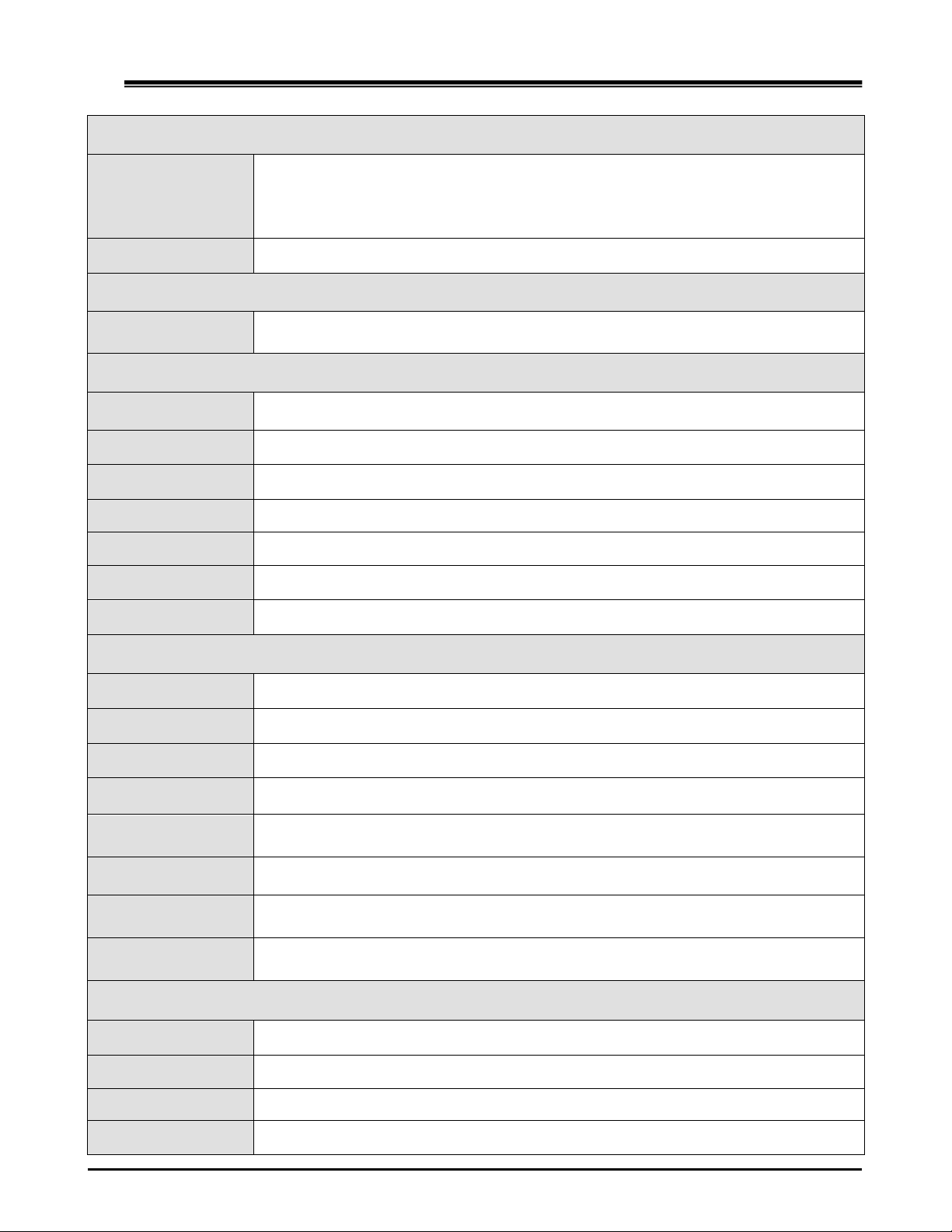
1.1 Model Specification
System
CPU
Intel Gen 3 Core i7-3517UE 1.7GHz
Intel Gen 3 Core i3-3217UE 1.6GHz
Intel Gen 3 Celeron Dual Core 1047E 1.4GHz
Memory
1 x DDR3 1066/1333/1600 MHz SO-DIMM up to 8 GB
Chipset QM77
LAN Chipset
Intel I210-AT Gb/s Ethernet Controllers Onboard
Support PXE and WOL
Audio Realtek ALC662 HD Codec onboard
Watchdog Watchdog Timer Support, Offer 1 – 255 Step
Power Requirement
Power Input 9V-32V DC Power input
Power Protection Automatics Recovery Short Circuit Protection
Power Management Vehicle Power Ignition for Variety Vehicle
Power Off Control Power off Delay Time Setting by Software
Battery
Internal Battery Kit for 10 Mins Operating (Optional)
Storage
Type
2 x 2.5” Drive Bay for SATA Type HDD / SSD, Support RAID 0, 1
1 x SATA DOM
6
Graphics
Graphics
Intel® HD Graphics 4000
DirectX Video Acceleration (DXVA) for Accelerating Video
Processing - Full AVC/VC1/MPEG2 HW Decode
Supports DirectX 11/10.1/10/9 and OpenGL 3.0
Resolution Up to 1920 x 1200
Qualification
Certifications CE, FCC Class A, eMark
I/O
Serial Port 4 x RS-232 (COM1,2 with RS-422/485, RS-485 Support Auto Direction Control)
USB Port 4 x USB 2.0 Ports on Front I/O
LAN 2 x RJ45 Ports for GbE
Video Port 1 x DVI-I, 1 x VGA and 1 x Display Port Output
DIO Port 4 in and 4 out with Relay 12V / 80mA
Audio 1 x Line-out and 1 x MIC-in
SIM Card Socket 2 x SIM Card sockets supported onboard with eject
Environment
Operating Temp. -40ºC ~ 70ºC (Default CPU 17Watt)
Storage Temp. -40 ~ 80ºC
Relative Humidity 0% RH– 95% RH
Vibration (random) 2.5g@5~500 Hz with SSD
Vibration Operating
MIL-STD-810F, Method 514.5, Category 20,
Ground Vehicle-Highway
Truck Storage MIL-STD-810F, Method 514.5, Category 24, Integrity Test
Shock
Operating: MIL-STD-810F, Method 516.5, Procedure I,
Trucks and semi-trailers=40G (11ms) with SSD
Crash Hazard
MIL-STD-810F, Method 516.5, Procedure V,
Ground equipment=100
Mechanical
Construction Aluminum alloy
Mounting Supports both of wall-mount/VESA-mount
Weight 1.780 kg (bare-bone)
Dimensions 250 x 150 x 55 mm
7
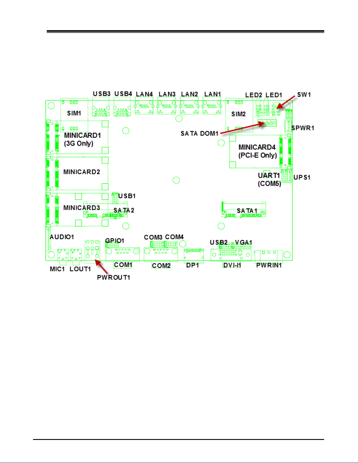
1.2 VBOX-3600 Illustration
Main board
8

System
9

(2) Internal connector specification
2.1 VGA connector
Connector
size
2 X 8 = 16 Pin
Connector
type
JST-2.0mm-M-180
Connector
location
VGA1
Connector
pin
definition
Pin
Signal
Pin
Signal
1
RED
2
GREEN
3
BLUE
4
NC
5
CER_DET
6
GND
7
GND
8
GND
9
+5V
10
GND
11
NC
12
DAC_SDA
13
HSYNC
14
VSYNC
15
DAC_SCL
16
NC
Connector
map
10

2.2 USB connector
Connector
size
2 X 4 = 8 Pin
Connector
type
JST-2.0mm-M-180
Connector
location
USB2 (Co-layout with DVI-I1)
Connector
pin
definition
Pin
Signal
Pin
Signal
1
5VSB
2
5VSB
3
USB_7N
4
NC
5
USB_7P
6
NC
7
GND
8
GND
Connector
map
11

2.3 USB connector
Connector
size
2 X 4 = 8 Pin
Connector
type
JST-2.0mm-M-180
Connector
location
USB3 (Co-layout with MINICARD3)
Connector
pin
definition
Pin
Signal
Pin
Signal
1
5VSB
2
5VSB
3
USB_6N
4
NC
5
USB_6P
6
NC
7
GND
8
GND
Connector
map
12

2.4 GPIO connector
Connector
size
2 X 5 = 10 Pin
Connector
type
JST-2.0mm-M-180
Connector
location
GPIO1
Connector
pin
definition
Pin
Signal
Pin
Signal
1
GPI0
2
GPI1
3
GPI2
4
GPI3
5
GPO0
6
GPO1
7
GPO2
8
GPO3
9
GND
10
+12V
Connector
map
13
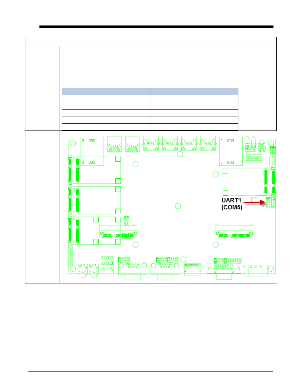
2.5 UART connector
Connector
size
2 X 5 = 10 Pin
Connector
type
JST-2.0mm-M-180
Connector
location
UART1 (COM5 for GPS Module when VDB-800 is installed)
Baud Rate : 9600
Connector
pin
definition
Pin
Signal
Pin
Signal
1
NC
2
COM5_RX
3
COM5_TX
4
NC
5
GND
6
NC
7
NC
8
GND
9
NC
10
+5V
Connector
map
14
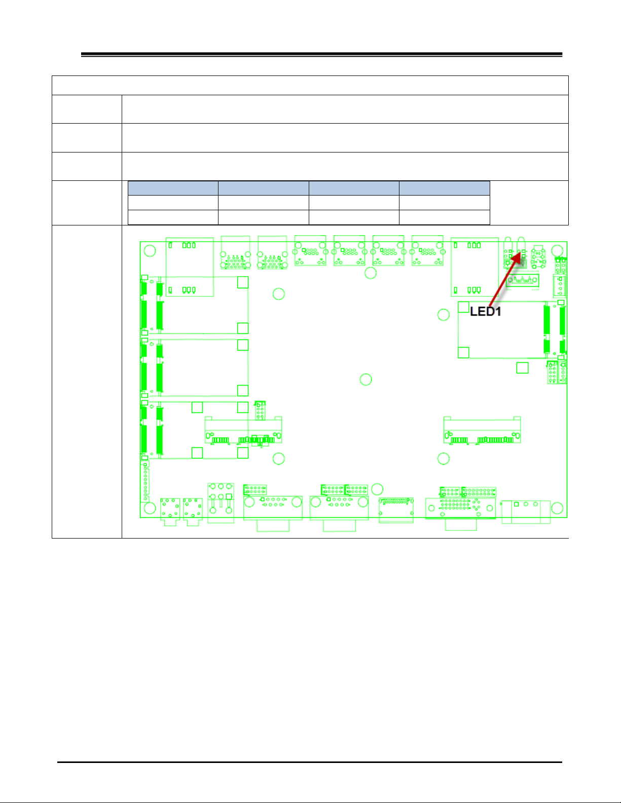
2.6 LED connector
Connector
size
2 X 2 = 4 Pin
Connector
type
LED WITH HOUSING
Connector
location
LED1
Connector
pin
definition
Pin
Signal
Pin
Signal
A1
3.5G_LED_P
A2
UPS_LED_P
C1
3.5G_LED_N
C2
UPS_LED_N
Connector
map
15

2.7 LED connector
Connector
size
2 X 2 = 4 Pin
Connector
type
LED WITH HOUSING
Connector
location
LED2
Connector
pin
definition
Pin
Signal
Pin
Signal
A1
ACC_LED_P
A2
HDD_LED_P
C1
ACC_LED_N
C2
HDD_LED _N
Connector
map
16
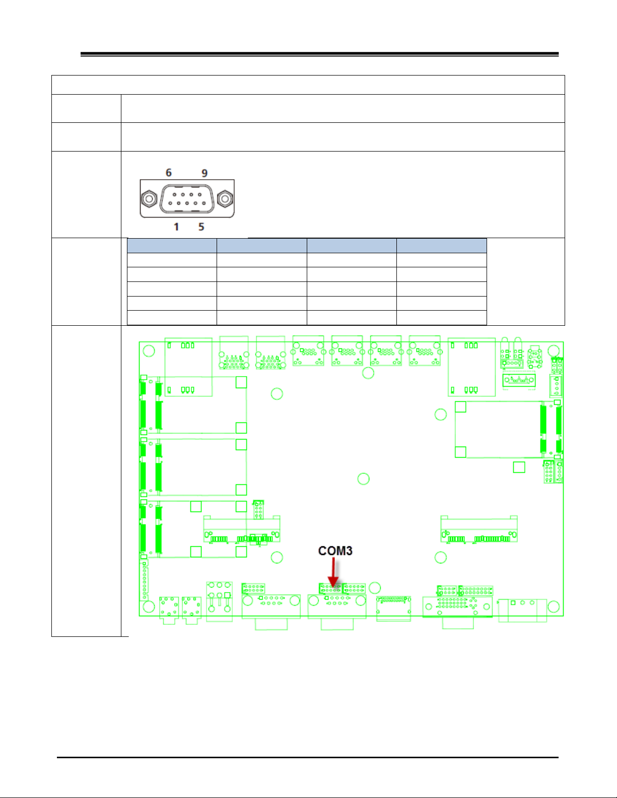
2.8 COM connector
Connector
size
2 X 5 = 10 Pin
Connector
type
JST-2.0mm-M-180
Connector
location
COM3
Connector
pin
definition
Pin
Signal
Pin
Signal
1
COM3_DCD
2
COM3_RXD
3
COM3_TXD
4
COM3_DTR
5
GND
6
COM3_DSR
7
COM3_RTS
8
COM3_CTS
9
COM3_RI
10
GND
Connector
map
17

2.9 COM connector
Connector
size
2 X 5 = 10 Pin
Connector
type
JST-2.0mm-M-180
Connector
location
COM4
Connector
pin
definition
Pin
Signal
Pin
Signal
1
COM4_DCD
2
COM4_RXD
3
COM4_TXD
4
COM4_DTR
5
GND
6
COM4_DSR
7
COM4_RTS
8
COM43_CTS
9
COM4_RI
10
GND
Connector
map
18

2.10 AUDIO connector
Connector
size
1 X 10 = 10 Pin
Connector
type
JST-2.0mm-M-180
Connector
location
AUDIO1
Connector
pin
definition
Pin
Signal
1
NC
2
NC
3
NC
4
NC
5
NC
6
NC
7
MIC_IN_ L
8
MIC_IN_R
9
MIC-JD
10
GND
Connector
map
19

2.11 SATA connector
Connector
size
1 X 7 = 7 Pin
Connector
type
SATA 1.27mm-M-180D
Connector
location
SATA DOM1
Connector
pin
definition
Pin
Signal
1
GND
2
SATA_TXP2
3
SATA_TXN2
4
GND
5
SATA_RXN2
6
SATA_RXP2
7
GND
Connector
map
20
Other manuals for VBOX-3600
1
Table of contents
Other Sintrones Automobile Accessories manuals


Popular Automobile Accessories manuals by other brands

Diode Dynamics
Diode Dynamics Demon Eyes installation guide

Innovate Motorsports
Innovate Motorsports PSB-1 user manual

Rhino-Rack
Rhino-Rack RCP58-BK manual

Motorola
Motorola Bluetooth Wireless Hands Free user guide

Dynojet
Dynojet Power Commander III Installation instructions manual

bosal
bosal ORIS 049-223 FITTING INSTRUCTION


Roadmaster
Roadmaster BASEPLATE KIT installation instructions

Blue Ox
Blue Ox BX1126 installation instructions

JKS
JKS PAC2151 installation instructions

Dynojet
Dynojet Power Commander V 22-027 installation instructions

HAUL MASTER
HAUL MASTER 92626 Set up and operating instructions

Cruz
Cruz Evo Rack Pro P38-158 Assembly instructions