Sintrones VBOX-3600 User manual
VBOX‐3600
In‐VehicleComputing
User'sManual
Version1.2
Document Name VBOX-3600 User Manual Document No. UM2013360010
Version 1.0 Date May. 17, 2013
Reversion History :
Reversion Date Notes Author(s)
From To
1.0 May 17, 2013 Initial document issued Stanley Chou
1.0 1.1 Oct 17, 2014 M12 Connecting to the Network Stanley Chou
1.1 1.2 Nov 26, 2014 CAN BUS Pin Assignment Stanley Chou

User’s Manual Page i
SINTRONES®TechnologyCorp.
UserManual
Copyright
©2009bySINTRONES®TechnologyCorp.AllRightsReserved.
Nopartofthispublicationmaybereproduced,transcribed,storedinaretrievalsystem,
translatedintoanylanguage,ortransmittedinanyformorbyanymeanssuchas
electronic,mechanical,magnetic,optical,chemical,photocopy,manual,orotherwise,
withoutpriorwrittenpermissionfromSINTRONES®TechnologyCorp.
Otherbrandsandproductnamesusedhereinareforidentificationpurposesonlyand
maybetrademarksoftheirrespectiveowners.
Disclaimer
SINTRONES®TechnologyCorp.shallnotbeliableforanyincidentalorconsequential
damagesresultingfromtheperformanceoruseofthisproduct.
SINTRONES®TechnologyCorp.makesnorepresentationorwarrantyregardingthe
contentofthismanual.Informationinthismanualhadbeencarefullycheckedfor
accuracy;however,noguaranteeisgivenastothecorrectnessofthecontents.For
continuingproductimprovement,SINTRONES®TechnologyCorp.reservestherightto
revisethemanualormakechangestothespecificationsofthisproductatanytime
withoutnoticeandobligationtoanypersonorentityregardingsuchchange.The
informationcontainedinthismanualisprovidedforgeneralusebycustomers.
ThisdevicecompliestoPart15oftheFCCRules.Operationissubjecttothefollowing
twoconditions:
1. Thisdevicemaynotcauseharmfulinterference.
2. Thisdevicemustwithstandanybackgroundinterferenceincludingthosethatmay
causeundesiredoperation.

User’s Manual Page ii
SafetyInformation
ReadthefollowingprecautionsbeforesettingupaSINTRONESProduct.
Electricalsafety
Topreventelectricalshockhazard,disconnectthepowercablefromtheelectrical
outletbeforerelocatingthesystem.
Whenaddingorremovingdevicestoorfromthesystem,ensurethatthepower
cablesforthedevicesareunpluggedbeforethesignalcablesareconnected.If
possible,disconnectallpowercablesfromtheexistingsystembeforeyouadda
device.
Beforeconnectingorremovingsignalcablesfromthemotherboard,ensurethatall
powercablesareunplugged.
Seekprofessionalassistancebeforeusinganadapterorextensioncord.These
devicescouldinterruptthegroundingcircuit.
Makesurethatyourpowersupplyissettothecorrectvoltageinyourarea.Ifyou
arenotsureaboutthevoltageoftheelectricaloutletyouareusing,contactyour
localpowercompany.
Ifthepowersupplyisbroken,donottrytofixitbyyourself.Contactaqualified
servicetechnicianoryourretailer.
Operationsafety
Beforeinstallingthemotherboardandaddingdevicesonit,carefullyreadallthe
manualsthatcamewiththepackage.
Beforeusingtheproduct,makesureallcablesarecorrectlyconnectedandthe
powercablesarenotdamaged.Ifyoudetectanydamage,contactyourdealer
immediately.
Toavoidshortcircuits,keeppaperclips,screws,andstaplesawayfrom
connectors,slots,socketsandcircuitry.
Avoiddust,humidity,andtemperatureextremes.Donotplacetheproductinany
areawhereitmaybecomewet.
Placetheproductonastablesurface.
Ifyouencountertechnicalproblemswiththeproduct,contactaqualifiedservice
technicianoryourretailer.

User’s Manual Page iii
CAUTION
Incorrectlyreplacingthebatterymaydamagethiscomputer.Replaceonlywiththe
sameoritsequivalentasrecommendedbySINTRONES®TechnologyCorp.Disposeused
batteryaccordingtothemanufacturer'sinstructions.
TechnicalSupport
Pleasedonothesitatetocallore‐mailourcustomerservicewhenyoustillcannotfix
theproblems.
Tel:+886‐2‐82280101
Fax:+886‐2‐82280100
E‐mail:sales@sintrones.com
Website:www.sintrones.com

User’s Manual Page iv
TABLEOFCONTENTS
Page #
1.0Introduction ............................................................................................................................... 1-1
1.1ModelSpecification.............................................................................................................. 1-1
1.2VBOX‐3600Illustration(MB,System).............................................................................. 1-3
2.0InternalConnectorSpecification ............................................................................................ 2-1
2.1VGAJSTConnector ............................................................................................................... 2-1
2.2USBJSTConnector(USB2).................................................................................................. 2-2
2.3USBJSTConnector(USB1).................................................................................................. 2-3
2.4GPIOJSTConnector.............................................................................................................. 2-4
2.5UARTJSTConnector ............................................................................................................ 2-5
2.6LEDJSTConnector(LED1).................................................................................................. 2-6
2.7LEDJSTConnector(LED2).................................................................................................. 2-7
2.8COMPortJSTConnector(COM3)....................................................................................... 2-8
2.9COMPortJSTConnector(COM4)....................................................................................... 2-9
2.10AUDIOJSTConnector......................................................................................................... 2-10
2.11SATA7PINConnector(SATA3)........................................................................................ 2-11
2.12SATA7PINConnector(SATA1)........................................................................................ 2-12
2.13SATA7PINConnector(SATA2)........................................................................................ 2-13
2.14MiniPCI‐ESlot:(MiniCard1) ........................................................................................... 2-14
2.15MiniPCI‐ESlot:(MiniCard2) ........................................................................................... 2-16
2.16MiniPCI‐ESlot:(MiniCard3) ........................................................................................... 2-18
2.17MiniPCI‐ESlot:(MiniCard4) ........................................................................................... 2-20
2.18PowerInputConnector ..................................................................................................... 2-22
2.19SATAPowerConnector(SPWR1).................................................................................... 2-23
2.20UPSPowerConnector........................................................................................................ 2-24
3.0ExternalConnectorSpecification............................................................................................ 3-1
3.1USB3.0TypeAConnector ................................................................................................... 3-1
3.2USB3.0TypeAConnector ................................................................................................... 3-2
3.3RJ45Connector(LAN1) ....................................................................................................... 3-3
3.4RJ45Connector(LAN2) ....................................................................................................... 3-4
3.5RJ45Connector(LAN3) ....................................................................................................... 3-5

User’s Manual Page v
3.6M12ConnectingtotheNetwork........................................................................................ 3-6
3.7RJ45Connector(LAN4) ....................................................................................................... 3-7
3.8DB29Connector(DVI‐I) ...................................................................................................... 3-8
3.9DPConnector......................................................................................................................... 3-9
3.10DB9Connector(COM1) ..................................................................................................... 3-10
3.11DB9Connector(COM2) ..................................................................................................... 3-11
3.12PHONEJACK(MICIN) ........................................................................................................ 3-12
3.13PHNEJACK(LINEOUT)...................................................................................................... 3-13
3.14ATX6PINConnector(POWEROUT) ............................................................................... 3-14
3.15CANBUSPinAssignment .................................................................................................. 3-15
4.0SystemInstallation ................................................................................................................... 4-1
4.1SystemIntroduction ............................................................................................................ 4-1
4.2OpeningChassis.................................................................................................................... 4-2
4.3InstallingMemory ................................................................................................................ 4-4
4.4InstallingMINIPCIeExpansionCard(PCIe1,3GModuleonly).................................. 4-6
4.5InstallingMINIPCIeExpansionCard(PCIe2) ................................................................ 4-8
4.6InstallingMINIPCIeExpansionCard(PCIe3) .............................................................. 4-10
4.7InstallingMINIPCIeExpansionCard(PCIe4,PCIeonly) ........................................... 4-12
4.8InstallingInternalAntennaCable................................................................................... 4-14
4.9InstallingSIMCard............................................................................................................. 4-18
4.10InstallingHDD..................................................................................................................... 4-20
4.11InstallingBatteryModule ................................................................................................. 4-23
5.0SystemResource ........................................................................................................................ 5-1
5.1IgnitionPowerManagementQuickGuide....................................................................... 5-1
5.2GPIO&DelayTimeSetting ................................................................................................. 5-3
5.2.1GPIOandIgnitionControlRegister................................................................................................. 5-3
5.2.2WDTSetting ...................................................................................................................................... 5-6
6.0BIOS ............................................................................................................................................. 6-1
6.1SuperIOConfiguration........................................................................................................ 6-1
7.0PackingList ................................................................................................................................ 7-1
7.1PackingList ........................................................................................................................... 7-1

1.0 Introduction
User’s Manual
1.0
INTRODUCTION
1.0 Introduction
User’s Manual Page 1-1
1.0 INTRODUCTION
1.1ModelSpecification
System
CPU
IntelGen3Corei7‐3517UE1.7GHz
IntelGen3Corei3‐3217UE1.6GHz
IntelGen3CeleronDualCore1047E1.4GHz
Memory1xDDR31066/1333/1600MHzSO‐DIMMupto8GB
ChipsetQM77
LANChipsetIntelI210‐ATGb/sEthernetControllersOnboard
SupportPXEandWOL
AudioRealtekALC662HDCodeconboard
WatchdogWatchdogTimerSupport,Offer1–255Step
PowerRequirement
PowerInput9V‐32VDCPowerinput
PowerProtectionAutomaticsRecoveryShortCircuitProtection
PowerManagementVehiclePowerIgnitionforVarietyVehicle
PowerOffControlPoweroffDelayTimeSettingbySoftware
BatteryInternalBatteryKitfor10MinsOperating(Optional)
Storage
Type2x2.5”DriveBayforSATATypeHDD/SSD,SupportRAID0,1
1xSATADOM
1.0 Introduction
User’s Manual Page 1-2
Graphics
Graphics
Intel®HDGraphics4000
DirectXVideoAcceleration(DXVA)forAcceleratingVideo
Processing‐FullAVC/VC1/MPEG2HWDecode
SupportsDirectX11/10.1/10/9andOpenGL3.0
ResolutionUpto1920x1200
Qualification
CertificationsCE,FCCClassA,E‐mark
I/O
SerialPort4xRS‐232(COM1,2withRS‐485SupportAutoDirectionControl)
USBPort4xUSB2.0PortsonFrontI/O
LAN2xRJ45PortsforGbE
VideoPort1xDVI‐I,1xVGAand1xDisplayPortOutput
DIOPort4inand4outwithRelay12V/80mA
Audio1xLine‐outand1xMIC‐in
SIMCardSocket2xSIMCardsocketssupportedonboardwitheject
Environment
OperatingTemp.‐40ºC~70ºC(DefaultCPU17Watt)
StorageTemp.‐40~80ºC
RelativeHumidity0%RH–95%RH
Vibration(random)2.5g@5~500HzwithSSD
VibrationOperatingMIL‐STD‐810F,Method514.5,Category20,GroundVehicle‐Highway
TruckStorageMIL‐STD‐810F,Method514.5,Category24,IntegrityTest
ShockOperating:MIL‐STD‐810F,Method516.5,ProcedureI,
Trucksandsemi‐trailers=40G(11ms)withSSD
CrashHazardMIL‐STD‐810F,Method516.5,ProcedureV,
Groundequipment=100
Mechanical
ConstructionAluminumalloy
MountingSupportsbothofwall‐mount/VESA‐mount
Weight1.780kg(bare‐bone)
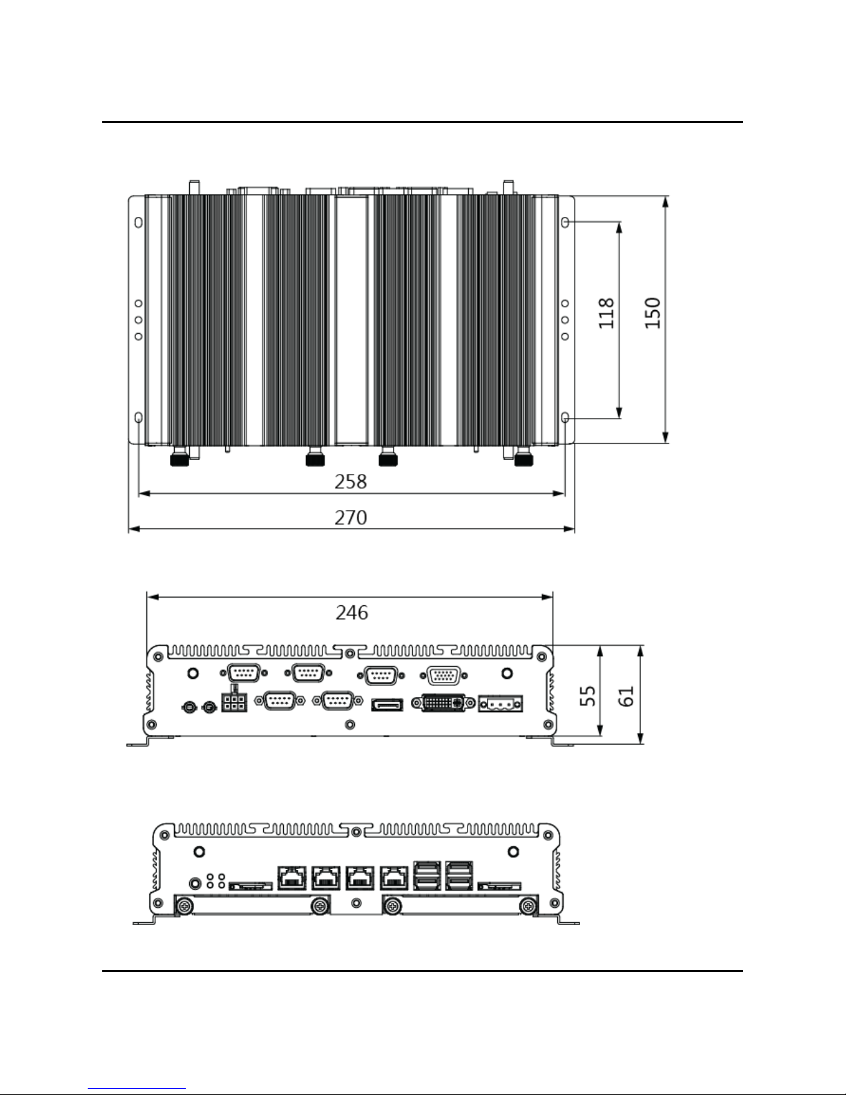
Dimensions250x150x55mm

1.0 Introduction
User’s Manual Page 1-3
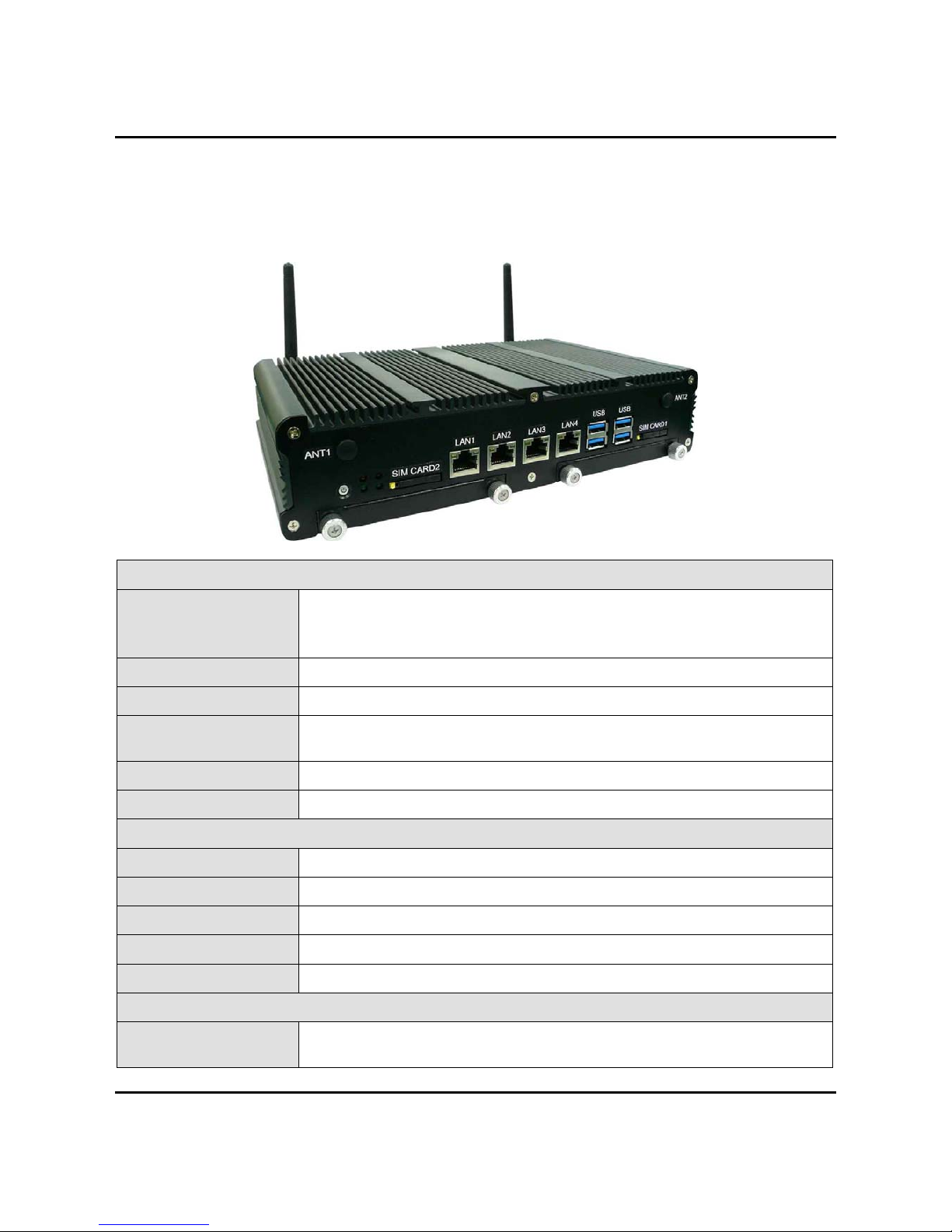
1.2 VBOX‐3600Illustration(MB,System)
MainBoard
1.0 Introduction
User’s Manual Page 1-4
System

2.0 Internal Connector Specification
User’s Manual
2.0
INTERNALCONNECTOR
SPECIFICATION

2.0 Internal Connector Specification
User’s Manual Page 2-1
2.0 INTERNALCONNECTORSPECIFICATION
2.1VGAJSTConnector
Connector
size 2 X 8 = 16 Pin
Connector
type JST-2.0mm-M-180
Connector
location VGA1
Connector
pin
definition
Pin Signal Pin Signal
1 RED 2 GREEN
3 BLUE 4 NC
5 CER_DET 6 GND
7 GND 8 GND
9 +5V 10 GND
11 NC 12 DAC_SDA
13 HSYNC 14 VSYNC
15 DAC_SCL 16 NC
Connector
map

2.0 Internal Connector Specification
User’s Manual Page 2-2
2.2USBJSTConnector(USB2)
Connector
size 2 X 4 = 8 Pin
Connector
type JST-2.0mm-M-180
Connector
location USB2 (Co-layout with DVI-I1)
Connector
pin
definition
Pin Signal Pin Signal
1 5VSB 2 5VSB
3 USB_7N 4 NC
5 USB_7P 6 NC
7 GND 8 GND
Connector
map
2.0 Internal Connector Specification
User’s Manual Page 2-3
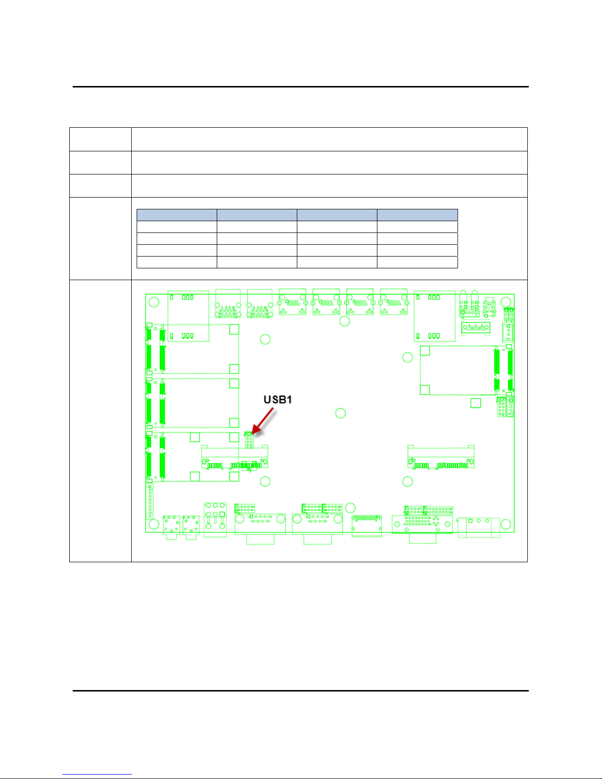
2.3USBJSTConnector(USB1)
Connector
size 2 X 4 = 8 Pin
Connector
type JST-2.0mm-M-180
Connector
location USB3 (Co-layout with MINICARD3)
Connector
pin
definition
Pin Signal Pin Signal
1 5VSB 2 5VSB
3 USB_6N 4 NC
5 USB_6P 6 NC
7 GND 8 GND
Connector
map

2.0 Internal Connector Specification
User’s Manual Page 2-4
2.4GPIOJSTConnector
Connector size 2 X 5 = 10 Pin
Connector type JST-2.0mm-M-180
Connector
location
GPIO1
Connector
pin definition
Pin Signal Pin Signal
1GPI0 2 GPI1
3GPI2 4 GPI3
5 GPO0 6 GPO1
7 GPO2 8 GPO3
9 GND 10 +12V
Connector map
2.0 Internal Connector Specification
User’s Manual Page 2-5
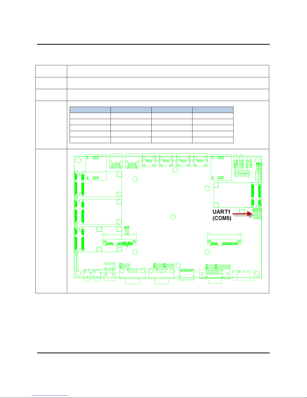
2.5UARTJSTConnector
Connector
size 2 X 5 = 10 Pin
Connector
type JST-2.0mm-M-180
Connector
location UART1 (COM5 for GPS Module when VDB-800 is installed)
Baud Rate : 9600
Connector
pin
definition
Pin Signal Pin Signal
1 NC 2 COM5
_
RX
3 COM5
_
TX 4 NC
5 GND 6 NC
7 NC 8 GND
9 NC 10 +5V
Connector
map

2.0 Internal Connector Specification
User’s Manual Page 2-6
2.6LEDJSTConnector(LED1)
Connector
size 2 X 2 = 4 Pin
Connector
type LED WITH HOUSING
Connector
location LED1
Connector
pin
definition
Pin Signal Pin Signal
A1 3.5G_LED
_
P A2 UPS_LED
_
P
C1 3.5G_LED
_
N C2 UPS_LED
_
N
Connector
map

2.0 Internal Connector Specification
User’s Manual Page 2-7
2.7LEDJSTConnector(LED2)
Connector
size 2 X 2 = 4 Pin
Connector
type LED WITH HOUSING
Connector
location LED2
Connector
pin
definition
Pin Signal Pin Signal
A1 ACC_LED
_
PA2HDD_LED
_
P
C1 ACC_LED
_
NC2HDD_LED
_
N
Connector
map
2.0 Internal Connector Specification
User’s Manual Page 2-8
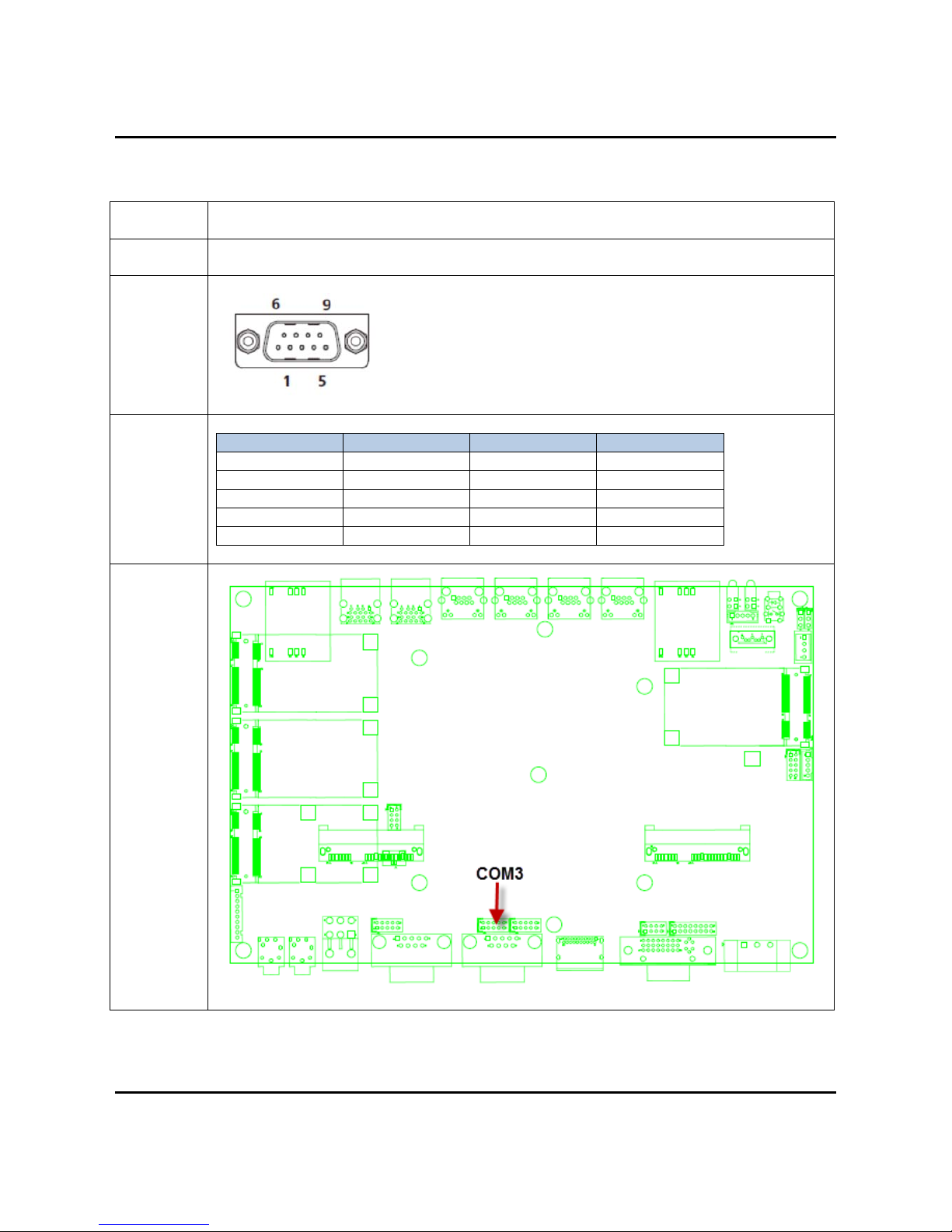
2.8COMPortJSTConnector(COM3)
Connector
size 2 X 5 = 10 Pin
Connector
type JST-2.0mm-M-180
Connector
location COM3
Connector
pin
definition
Pin Signal Pin Signal
1 COM3
_
DCD 2 COM3
_
RXD
3 COM3
_
TXD 4 COM3
_
DT
R
5 GND 6 COM3
_
DS
R
7 COM3
_
RTS 8 COM3
_
CTS
9 COM3
_
RI 10 GND
Connector
map
Other manuals for VBOX-3600
1
Table of contents
Other Sintrones Automobile Accessories manuals


