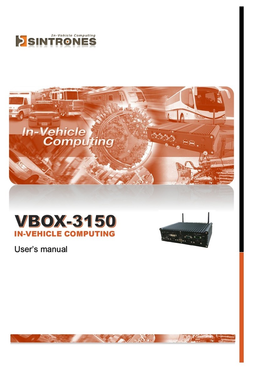
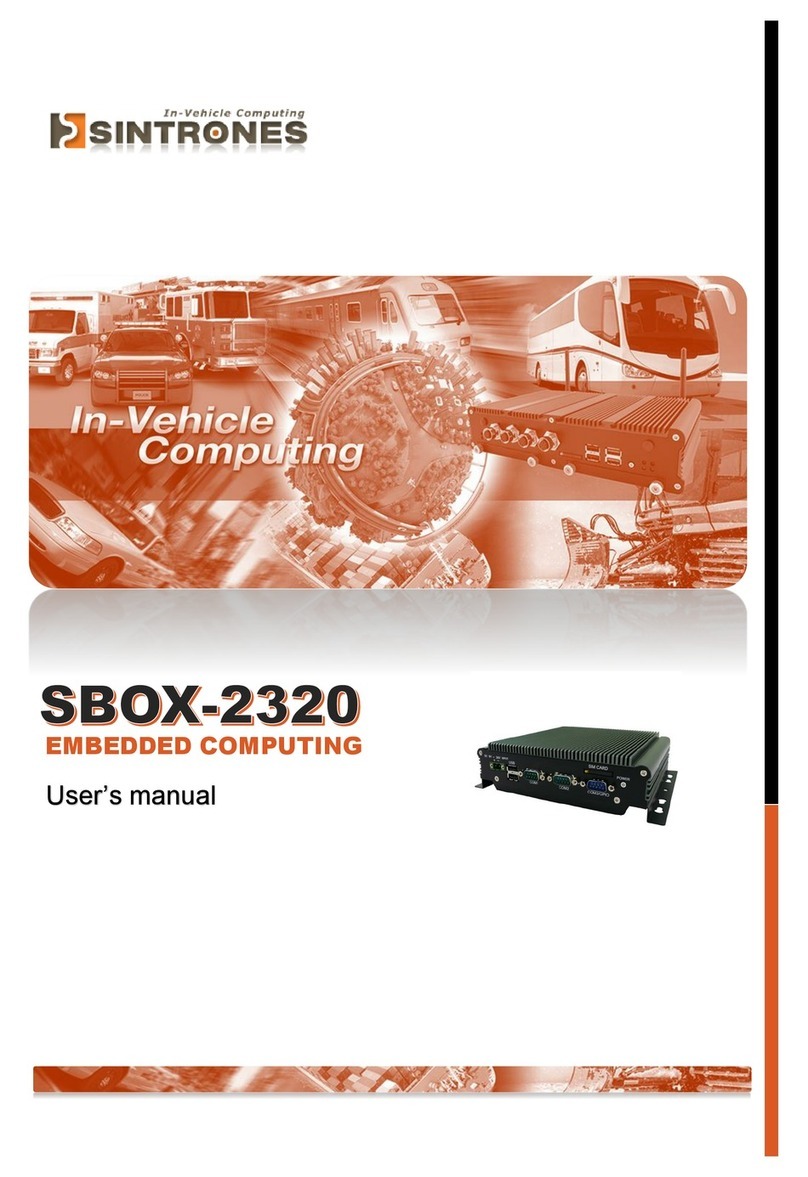
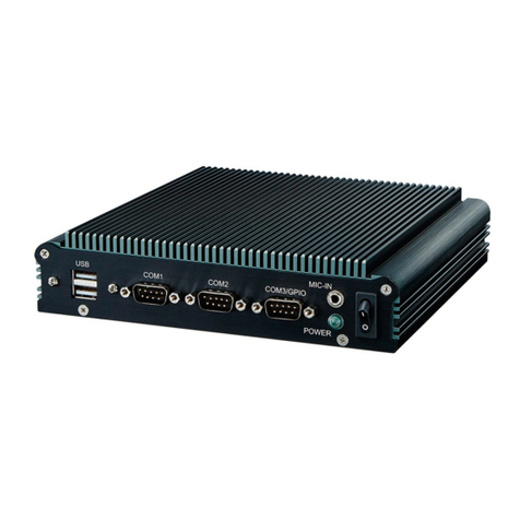
Sintrones VBOX-3120 User manual

VBOX-3120
In-Vehicle Computing
User's Manual
Version 1.1
Document Name VBOX-3120 User Manual Document No. UM2015312010
Version 1.1 Date Feb. 3, 2015
Reversion History :
Reversion Date Notes Author(s)
From To
1.0 Feb. 3, 2015 Initial document issued Stanley Chou

User’s Manual Page i
SINTRONES®TechnologyCorp.
UserManual
Copyright
©2009bySINTRONES®TechnologyCorp.AllRightsReserved.
Nopartofthispublicationmaybereproduced,transcribed,storedinaretrievalsystem,
translatedintoanylanguage,ortransmittedinanyformorbyanymeanssuchas
electronic,mechanical,magnetic,optical,chemical,photocopy,manual,orotherwise,
withoutpriorwrittenpermissionfromSINTRONES®TechnologyCorp.
Otherbrandsandproductnamesusedhereinareforidentificationpurposesonlyand
maybetrademarksoftheirrespectiveowners.
Disclaimer
SINTRONES®TechnologyCorp.shallnotbeliableforanyincidentalorconsequential
damagesresultingfromtheperformanceoruseofthisproduct.
SINTRONES®TechnologyCorp.makesnorepresentationorwarrantyregardingthe
contentofthismanual.Informationinthismanualhadbeencarefullycheckedfor
accuracy;however,noguaranteeisgivenastothecorrectnessofthecontents.For
continuingproductimprovement,SINTRONES®TechnologyCorp.reservestherightto
revisethemanualormakechangestothespecificationsofthisproductatanytime
withoutnoticeandobligationtoanypersonorentityregardingsuchchange.The
informationcontainedinthismanualisprovidedforgeneralusebycustomers.
ThisdevicecompliestoPart15oftheFCCRules.Operationissubjecttothefollowing
twoconditions:
1. Thisdevicemaynotcauseharmfulinterference.
2. Thisdevicemustwithstandanybackgroundinterferenceincludingthosethatmay
causeundesiredoperation.

User’s Manual Page ii
SafetyInformation
ReadthefollowingprecautionsbeforesettingupaSINTRONESProduct.
Electricalsafety
Topreventelectricalshockhazard,disconnectthepowercablefromtheelectrical
outletbeforerelocatingthesystem.
Whenaddingorremovingdevicestoorfromthesystem,ensurethatthepower
cablesforthedevicesareunpluggedbeforethesignalcablesareconnected.If
possible,disconnectallpowercablesfromtheexistingsystembeforeyouadda
device.
Beforeconnectingorremovingsignalcablesfromthemotherboard,ensurethatall
powercablesareunplugged.
Seekprofessionalassistancebeforeusinganadapterorextensioncord.These
devicescouldinterruptthegroundingcircuit.
Makesurethatyourpowersupplyissettothecorrectvoltageinyourarea.Ifyou
arenotsureaboutthevoltageoftheelectricaloutletyouareusing,contactyour
localpowercompany.
Ifthepowersupplyisbroken,donottrytofixitbyyourself.Contactaqualified
servicetechnicianoryourretailer.
Operationsafety
Beforeinstallingthemotherboardandaddingdevicesonit,carefullyreadallthe
manualsthatcamewiththepackage.
Beforeusingtheproduct,makesureallcablesarecorrectlyconnectedandthe
powercablesarenotdamaged.Ifyoudetectanydamage,contactyourdealer
immediately.
Toavoidshortcircuits,keeppaperclips,screws,andstaplesawayfrom
connectors,slots,socketsandcircuitry.
Avoiddust,humidity,andtemperatureextremes.Donotplacetheproductinany
areawhereitmaybecomewet.
Placetheproductonastablesurface.
Ifyouencountertechnicalproblemswiththeproduct,contactaqualifiedservice
technicianoryourretailer.

User’s Manual Page iii
CAUTION
Incorrectlyreplacingthebatterymaydamagethiscomputer.Replaceonlywiththe
sameoritsequivalentasrecommendedbySINTRONES®TechnologyCorp.Disposeused
batteryaccordingtothemanufacturer'sinstructions.
TechnicalSupport
Pleasedonothesitatetocallore‐mailourcustomerservicewhenyoustillcannotfix
theproblems.
Tel:+886‐2‐82280101
Fax:+886‐2‐82280100
E‐mail:sales@sintrones.com
Website:www.sintrones.com

User’s Manual Page iv
TABLEOFCONTENTS
Page #
1.0Introduction ............................................................................................................................... 1-1
1.1ModelSpecification.............................................................................................................. 1-1
1.2VBOX‐3120Illustration(MB,System).............................................................................. 1-3
1.3Architecture .......................................................................................................................... 1-5
1.4PrincipalComponentSpecification .................................................................................. 1-6
2.0InternalConnectorSpecification ............................................................................................ 2-1
2.1VGAConnector ...................................................................................................................... 2-1
2.2USBConnector(USB2)......................................................................................................... 2-2
2.3USBConnector(USB3)......................................................................................................... 2-3
2.4GPIOConnector..................................................................................................................... 2-4
2.5UARTandGPIOConnector ................................................................................................. 2-5
2.6LEDConnector ...................................................................................................................... 2-6
2.7COMConnector(COM1) ...................................................................................................... 2-7
2.8COMConnector(COM2) ...................................................................................................... 2-8
2.9COMConnector(COM3) ...................................................................................................... 2-9
2.10COMConnector(COM4) .................................................................................................... 2-10
2.11AUDIOConnector ............................................................................................................... 2-11
2.12SATAConnector(SATA1).................................................................................................. 2-12
2.13SATAConnector(SATA2).................................................................................................. 2-13
2.14MiniPCI‐EConnector(MINICARD1) ............................................................................... 2-14
2.15MiniPCI‐EConnector(MINICARD2) ............................................................................... 2-16
2.16PowerInputConnector ..................................................................................................... 2-18
2.17SATAPowerConnector(SPWR1).................................................................................... 2-19
2.18SATAPowerConnector(SPWR2).................................................................................... 2-20
3.0ExternalConnectorSpecification............................................................................................ 3-1
3.1USBConnector ...................................................................................................................... 3-1
3.2LANConnector(LAN1) ........................................................................................................ 3-2
3.3LANConnector(LAN2) ........................................................................................................ 3-3
3.4DVI‐IConnector .................................................................................................................... 3-4
3.5HDMIConnector ................................................................................................................... 3-5

User’s Manual Page v
3.6AudioConnector................................................................................................................... 3-6
3.6PowerInputConnector ....................................................................................................... 3-7
3.7DIOConnector....................................................................................................................... 3-8
4.0SystemInstallation ................................................................................................................... 4-1
4.1SystemIntroduction ............................................................................................................ 4-1
4.2OpeningChassis.................................................................................................................... 4-2
4.3InstallingMemory ................................................................................................................ 4-4
4.4InstallingHDD/SSD ............................................................................................................ 4-6
4.5InstallingMINIPCIeExpansionCard................................................................................ 4-8
4.6InstallingMINIPCIeExpansionCard.............................................................................. 4-10
4.7InstallingSIMCard............................................................................................................. 4-12
4.8InstallingBatteryModule ................................................................................................. 4-14
5.0SystemResource ........................................................................................................................ 5-1
5.1IgnitionPowerManagementQuickGuide....................................................................... 5-1
6.0BIOS ............................................................................................................................................. 6-1
6.1EnterTheBIOS...................................................................................................................... 6-1
6.2Main ........................................................................................................................................ 6-3
6.3Advanced................................................................................................................................ 6-4
6.4Chipset.................................................................................................................................. 6-10
6.5Boot ....................................................................................................................................... 6-13
6.6Security ................................................................................................................................ 6-15
6.7Exit ........................................................................................................................................ 6-16
7.0PackingList ................................................................................................................................ 7-1
7.1PackingList ........................................................................................................................... 7-1

1.0 Introduction
User’s Manual
1.0
INTRODUCTION

1.0 Introduction
User’s Manual Page 1-1
1.0 INTRODUCTION
1.1ModelSpecification
System
CPUIntelGen4DualCore2980U1.6GHz
Memory1xDDR3L‐1600SO‐DIMMupto8GB
GraphicsIntelHDGraphics
ATA2xSerialATA2.0Portswith6Gb/sHDDTransferRate
LANChipset2xInteli210‐ATGigabitEthernet
Watchdog1~255levelreset
I/O
SerialPortSuuport1xRS‐232(COM1withRS‐232/422/485)
USBPort3xUSB2.0ports
LAN2xRJ45portsforGbE
VideoPort1xHDMIandDVI‐I
GPIOPortSupport2Inand2Out(12V/100mA)
AudioMic‐in/Line‐out
ExpansionBus3xMini‐CardSlots
SIMCardSocket2xSIMCardsocketssupportedonboardwitheject
Antenna4xSMA‐typeExternalAntennaConnectorsforWLAN/UMTS/
GSM/GPRS/GPS/Bluetooth

1.0 Introduction
User’s Manual Page 1-2
Storage
Type1x2.5”drivebayforSATATypeHardDiskDrive/SSD
1xSATADOM
PowerManagement
PowerInput9V‐36VDCPowerInput
PowerManagementVehiclePowerIgnitionforVarietyVehicle
PowerOffControlPoweroffDelayTimeSettingbySoftware,Defaultis5Mins
BackupBatteryInternalBatteryKitfor10MinsOperating(Optional)
Qualification
CertificationsCE,FCCClassA,eMarkCompliance
Environment
OperatingTemp.‐40~70ºC(SSD),ambientw/air
StorageTemp.‐40~80ºC
RelativeHumidity5~90%(non‐condensing)
Vibration(random)2.5g@5~500HzwithSSD
VibrationOperatingMIL‐STD‐810F,Method514.5,Category20, GroundVehicle‐
Highway
TruckStorageMIL‐STD‐810F,Method514.5,Category24,IntegrityTest
ShockOperating:MIL‐STD‐810F,Method516.5,ProcedureI,Trucks and
semi‐trailers=15G(11ms)withSSD
CrashHazardMIL‐STD‐810F,Method516.5,ProcedureV, Ground
equipment=100
Mechanical
ConstructionAluminumalloy
MountingSupportsbothofwall‐mount/VESA‐mount
Weight1.406g
Dimensions182x167.6x52mm

1.0 Introduction
User’s Manual Page 1-3
1.2 VBOX‐3120Illustration(MB,System)
MainBoard

1.0 Introduction
User’s Manual Page 1-4
System

1.0 Introduction
User’s Manual Page 1-5
1.3Architecture
DVI
VGA DVI - I
SPI ROM
128Mb
SPI BUS
HDMI HDMI
RS232/422/485
Generation 4
CPU Intel Core
i7-4650U
i5-4300U
i3-4010U
2980U
Processor
SoC
Haswell - ULT
DDR3L 1333~1066 MHz max:8GB
SO-DIMM A0
Voltage monitor
TEMPS monitor
GPIO/TTL
GPIO 4 in / 4 out
JST CON.
HW Monitor
SUPER I/O
FINTEK F81865-I
LPC BUS
COM PORT 1
DB9 CON.
COM PORT 3
JST CON.
GPIO 3 in / 3 out
JST CON.
RS232
RS232/422/485
COM PORT 2
JST CON.
COM PORT 4
JST CON.
RS232
SATA II
SATA PORT 2
7 PIN CON. SATA PORT 1
7 PIN CON.
w/SATA DOM
GPIO/TTL
Intel
WGI210AT
GBE 0
PCI-E X1 BUS 0
Intel
WGI210AT
GBE 1
PCI-E X1 BUS 1 MDIBUS
MDI BUS
RJ45
PORT 1
w/LED
RJ45
PORT 0
w/LED
USB 2.0
USB 2.0
Mini PCI-E Slot 1
Half / Full Size
Mini PCI-E Slot 0
Full Size
PCI-E X1 BUS 2
Realtek
ALC662
HD Codec
PCI-E X1 BUS 3
LINEOUT
LINE OUT
HDAudio
USB PORT 2~4
JST CON.
USB 2.0
USB PORT 0~1
Edge CON.
USB 3.0
JST CON.
MIC OUT
MIC IN
LINEIN
LINE IN
LINEOUT
PHONE JACKLINE OUT

1.0 Introduction
User’s Manual Page 1-6
1.4PrincipalComponentSpecification
CPU
ChipDescription
Intel1.PowerConsumption:
SymbolProcessor
Number
Core
Frequency/
GHz
Thermal
Design
Power
Unit Tj
min
(°C)
Cache
TDP2980U
i3‐4010U
i5‐4300U
i7‐4650U
1.6
1.7
1.9‐2.9
1.7–3.3
15
15
15
15
W
W
W
W
100
100
100
100
2M
3M
3M
4M

2.0 Internal Connector Specification
User’s Manual
2.0
INTERNALCONNECTOR
SPECIFICATION

2.0 Internal Connector Specification
User’s Manual Page 2-1
2.0 INTERNALCONNECTORSPECIFICATION
2.1VGAConnector
Connector size 2 X 8 = 16 Pin
Connector type JST-2.0mm-M-180
Connector location VGA1
Connector pin definition Pin Signal Pin Signal
1 RED 2 GREEN
3 BLUE 4 NC
5 CER_DET 6 GND
7 GND 8 GND
9 +5V 10 GND
11 NC 12 DAC_SDA
13 HSYNC 14 VSYNC
15 DAC_SCL 16 NC
Connector map

2.0 Internal Connector Specification
User’s Manual Page 2-2
2.2USBConnector(USB2)
Connector size 2 X 4 = 8 Pin
Connector type JST-2.0mm-M-180
Connector location USB2
Connector pin definition Pin Signal Pin Signal
1 5VSB 2 5VSB
3 USB2_N 4 USB3_N
5 USB2_P 6 USB3_P
7 GND 8 GND
Connector map

2.0 Internal Connector Specification
User’s Manual Page 2-3
2.3USBConnector(USB3)
Connector size 2 X 4 = 8 Pin
Connector type JST-2.0mm-M-180
Connector location USB3
Connector pin definition Pin Signal Pin Signal
1 5VSB 2 5VSB
3 USB4_N 4 NC
5 USB4_P 6 NC
7 GND 8 GND
Connector map

2.0 Internal Connector Specification
User’s Manual Page 2-4
2.4GPIOConnector
Connector size 2 X 5 = 10 Pin
Connector type JST-2.0mm-M-180
Connector location GPIO1
Connector pin definition Pin Signal Pin Signal
1 GND 2 +5V
3 GPI0 4 GPO0
5 GPI1 6 GPO1
7 GPI2 8 GPO2
9 GPI3 10 GPO3
DB9 pin definition
Pin Signal
GPIO
1 GPI0
2 GPI1
3 GPI2
4 GPI3
5 GPO0
6 GPO1
7 GPO2
8 GPO3
9 GND
Connector map

2.0 Internal Connector Specification
User’s Manual Page 2-5
2.5UARTandGPIOConnector
Connector size 2 X 5 = 10 Pin
Connector type JST-2.0mm-M-180
Connector location UART1
Connector pin definition Pin Signal Pin Signal
1 GPIO0 2 GPIO6
3 GPIO5 4 GPIO4
5 GND 6 GPIO3
7 GPIO1 8 GND
9 GPIO2 10 +5V
Connector map

2.0 Internal Connector Specification
User’s Manual Page 2-6
2.6LEDConnector
Connector size 2 X 5 = 10 Pin
Connector type JST-2.0mm-M-180
Connector location LED1
Connector pin definition Pin Signal Pin Signal
1 HDD_LED_N 2 HDD_LED_P
3 PWR_LED_N 4 PWR_LED_P
5 GND 6 PWRBT#
7 GND 8 HW_RESET#
9 SMB_CLK 10 SMB_DATA
Connector map
Table of contents
Other Sintrones Automobile Accessories manuals
Popular Automobile Accessories manuals by other brands

Westfalia
Westfalia SIARR 307376600001 Assembly instructions

Hamax
Hamax Zenith user manual

SICK
SICK 3vistor-P CV operating instructions

Hollywood Racks
Hollywood Racks Road Runner 3 Series Assembly and installation instructions

Porsche
Porsche Home Energy Manager manual

TES
TES 520571 installation instructions

Calix group
Calix group TYP MVP 823 Assembly instructions

Conrad
Conrad 855238 operating instructions

JVC
JVC KW-DB70AT Installation/configuration

Road Shower
Road Shower Road Shower 2 owner's manual

Tar River Implements
Tar River Implements BRB 500 Series Operation and parts manual

APS
APS IA04SBE8B installation instructions