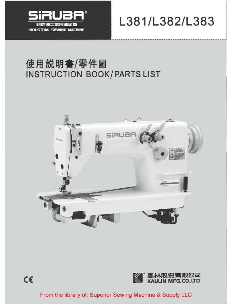
Siruba FA007 Datasheet

FA007
1im~a~W*f!:FII
·
INSTRUCTION AND PARTS LIST
·
Sir:.UaFr
·
CE
GE
ml
®
ai~fti1S3f5i~~fla]
~
KAULIN
MFG
~
CO
..
LTD
.
From the library of: Superior Sewing Machine & Supply LLC

From the library of: Superior Sewing Machine & Supply LLC

From the library of: Superior Sewing Machine & Supply LLC

(f)FEATURES
*The
DT6-927
F
eed
-off-th
e-Arm
Double
Chain S
tit
ch Machine is
most
suitable for
sewing
th
e
tu
bular
p
ar
ts of shirts, pyjamas,
work
clothes,
swe
at
pant
s, etc.
*High
speed
operat
ion
at
4,000
st
itches
per
minute
will incr
ease
production efficiency.
*TheDT6-
927 employs ball
bearings
where
necessary
and
all
working
p
arts
are
com-
pletely lubri
ca
ted.
*The.machine
can
be
arranged
in a
way
most
suitable
for
factory
line
operation
by
u
se
of
special
motor
bases.
CONTENTS
~
SPECIFICATIONS
~
............
............
..
..........
1
~
Sewing
........
...
.................
.....
................
.......
......
.....4
~
TAB
LE
OF
STANDARD
GAUGES
»
..........
1
[§]
Thr
ead
Tension
...............
...
........
................
............
5
1Zl
Presser
Foot
Pressure Adjustment
..............
·
........
·..·.. 5
~
J
N
STA
L
LING
~
............
..
........................
..
........
l
[I]
Ins
talling
the Machine
He
ad
....................................
l
121
Installing
th
e
Treadl
e and Chain ....
........
.
......
....
....
... 2
~
Stit
ch Le
ngth
Adju
st
ment
..
.......................................
5
~
Puller
Feed
Adju
stment(Mo
del
927-S
/
M-PL
) ............5
~
STANDARD
ADJUSTMENTS»
....
.........
......
7
(3]
In
sta
lling
the
Motor
Pulley
....................................
2 [I] Needle
and
Lo
oper
Timing
Adju
stment
...
........
.........
·7
~
Belt
Tension
Adjustme
nt
........
...................
........
....· 2
~
Needle
bar
Height Adjustment
....
............
.............
.....
7
[5)
Installing
th
e
Belt
Cover....·
..............
·..·..·..·
........
·.... 2
@]
Timing
of Loopers Running
Clear
of
Need
l
es
.........
....8
161
Motor
and
Motor
Pulley
..........................................
2
~
Needle
Guard
Adjustment
............
.......
...........
..........
8
111
Spool
Sta
nd
....·
....
..........................
·
........
··
....
..........
2 [5]
Feed
Dog
Height
Adj
ustment"
...............
....
........
..
.....
9
~
LUBRICAT
I
O
N
.
AND. RUNNING
IN
~
......
3
[I]
Lubrication
···
.....
·..
.........
·
.................
·.. ··
.................
3
121
Running In ....
.............
............
....................
....
......
· 3
[§]
Upper
Thread
Take
-up
Thread
Guide Adjustment
......
9
11J
Upper
Thread
Arm
Thr
ead
Guide Adjustment
...........
10
1§1
Th
r
ead
Release
Sha
ft
Adjustment
.......
.....................
10
~
Low
er
Thread
Tak
e-
up
Timing
Adjustment.....
.........
1Q
~
CORRECT
OP
E
RATION
~
...........................
3
[I]
Needl
es
and
Thread
s
.....
..............
..........................
3
(2]
In
st
alling
the
Need
l
es
......·
........
··
...
···
...................
··· 3
[I2J
In
sta
lling
th
e Lapper·..·
...
.·
........................
.............
·
lO
[1]
Puller
Height
Ad
justme
nt (Model 92
7-
S/M
-PL)
........
11
~
Puller Devi
ce
Timing
Adjustment(
Mod
el 927-S/ M- PL)
@]
Lower
Threading··
·········
····
·
···········
·························
4
~
TROUBLESHOO
TI
NG
»
......
...........
..
..
...........
12
~
Upper
Threading
·····..···········..···..········.. ·..·········..···4
From the library of: Superior Sewing Machine & Supply LLC

~1~
(SPECIFICATIONS)
Model
FA007
Use
Thin
materials
I Medium-thick
materials
IThick materials
Stitch
pattern
Twin
-needle,
twin
-
thread
double
chain
stitch, parallel sewing
Max
.
se
wing
speed 3,600
spm
4,000 spm
Stitch
l
engt
h 1.2
-2.5
mm
1
.2-3.2
mm
Needle
gauge
)(5
inch
(4.8
mm) I
Ys
inch
(3.2
mm)
I%
inch
(4
mm)I
~
inch
(4.8
mrn)
IU
inch
(6.4
mrn)
Needle
TVxl
Needle
bar
s
troke
27
mm
I
27mm
I 30
mm
Min
.
arm
size 178mm
Puller
device Equipped_
_j___
_ None
(TABLE
OF
STANDARD
GAUGES)
Ga
uge
set
Needle
ho
lde
r
Needle
plate
Presser
foot
Feed
dog
Looper
assemblY
.
Looper
thread
Lapper
oruide .....,
Y.MH
Ya
Ya
Ya Ya
Ya
Ya
Ya
MH
!J<s
MH
!J<s
!J<s
!J<s !J<s !J<s
Ya
~~
MH
Y.
MH
Y.
Y.
H
Y.H
Y.
H
Y.
H
Y.H
Y.MH
(INSTALLING)
[]]
Installing
the
Machine
Head
1.
Install pulley
cover
ba
se
8
on
machine
bed
0 wi
th
two
h
ex
l"g
onal
bolt
s
@).
2.
In
sert
bar
cushions
0
int
o
the
holes in
th
e
bottom
of
th
e bed.
3.
Place
the
m
ac
hine h
ea
d on
the
table
,
adjust
its position in
forward
and
ba
c
kward
dire
c
tions
by
a
li
gning it with the hole for.
presser
bar
lifter
c
hain
0 .
and
in sidewise
dir
ec
tions
by
aligning it
with
be
lt
hole e.
4. After
fastening
cushions
8
to
the
ma
chine
bed
and
pulley
cover
ba
se
with
set
screws
e.fix them
to
the
table
with screws 0
From the library of: Superior Sewing Machine & Supply LLC

~2~
121
Installing
the
Treadle
and
Chain
L_ _
1.
Fa
sten
connecting
lever
bearing
8
to
the
beam
in
th
e u
pper
part
of
the
tab
le l
eg
s
with
nut • ·
2. Slide
conne
ct
ing le
ver
L 0 onto
connecting
l
ever
s
haft
8 .
3.
Fit
co
nnecting lever s
haft
• to
co
nnecting
le
ver
be
aring
e.
and
sec
ure
it w
it
h
co
nnecti
ng
lever sh
af
t collar e.
4.
Set
co
nne
cting lev
er
L 0 in
li
ne
with
the
clutch
l
ever
hole.
and
tighten it with s
quare
h
ead
bol
ts
• .
5.
Ho
ok
co
nn
ect
ing rod 0 to
the
clut
ch lev
er
and
co
nnect
in
g l
ever
L
G.
6. Slide
anoth
er connecting le
ver
L 0 on
to
co
nnecting l
eve
r s
haft
e.and
fix
it with
sq
uare
head
bo
l
ts
• .
7.
Fast
en
treadl
e shaft 0
onto
the
l
ow
er
beam
ac
ross
the
tab
le l
egs
with
h
exagonal
bo
l
ts
Cl)
.
8.
Siide pedal stopper 8 and
presser
foot
li
fter
pe
da
l e
ont
o
treadl
e shaft 0 .
and
fasten it wi
th
pedal stopp
er
e.
9. Slide
treadl
e st
op
p
er
e
and
t
re
ad
le •
onto
tread
le
shaft
G. and f
asten
tr
ead
le s
topper
e in such a
way
that
treadle
•
will move lightly.
10
. Slide t
re
edle
support e
on
to the end
of
tre
adle shaft 0 . turn
it
unt
il
tr
eadle shaft G is
pa
rallel with the
fl
oor.
and
fasten it.
11.
Ho
ok
one
end of
co
nnecting rod 8
to
connec
ting
lever L 8 .
and
hook the
other
end of it
to
tre
adle • .
1
2.
H
ook
one
end
of
chain e to
the
pre
sse
r
foot
lift
er
lever. pass the oth
er
end
through
the hole in presser foot lift
er
peda
l • .
and
adj
ust
the
chai
n len
gth
so
tha
t
the
pedal will be
at
the s
am
e height
as
tread
le e.
[3]
Installing
the
Motor
Pulley
With
!pOto·r
shaft
ke
y way 8 up. in
sert
key e
into
the
ke
y
wa
y, slide
motor
Pulley
f)
onto
the
moto
r
shaft.
and
fasten
it
with
nut 8 .
~
Belt
Tension
adjustment
/
·-·
·
• -·
Pl
ace
belt e
on
machin
e pulley 8 and
motor pull
ey
• .
an
d adju
st
the belt t
en
·
sion with
tension
regulat
or
8
so
t
hat
the
belt
sags
a
bout
25
to 30 mm wh
en
it is
pr
essed
with
the
t
hu
mb
at
th
e
center
poi
nt
between
the
pulleys.
LlJ
Spool
Stand
15.1
Installing Belt
Cover
In
sta
ll
belt c
over
8 on the pulley cover
base
with
set
screws
e.
161
Motor
and
Motor
Pulley
1.
Motor
Use
the m
otor
spec
ifi
ed
below. Assemble sp
oo
l
stand
8
as
shown below. and install
it
at
Thr
ee-phase
2-
pole, 400 W
mo
tor:]
2.
Motor
Pulley
Use
th
e
correct
mot
or pull
ey
s
uit
able
to
th
e fre·
q
uen
cy
of
your
power
sup
ply
as
specified
be
low.
F
Sewing
speed
Motor
pull
ey
Belt
size
50Hz
3,
600
90
M-44
4,000
100
60Hz 3,
600
75
M-4
3
4,000
85
the right
rear
co
rn
er of
th
e
tab
le with
sc
rews.
From the library of: Superior Sewing Machine & Supply LLC

~3~
~LUBRICATION
AND
RUNNING
IN~
ill
lubrication
Be
sure
to
oil
the
following
points
before using
your
sewing machine.
1.
After
setting
up
the
machine
, remove adjusting
cover
screw
e.
and
pour
oil in
up
to
the
reference
line on oil gauge e.
2.
Turn
the
pulley until oil
ca
p e is
up
, remove oil
cap
e
and
pour
oil into oil
tank
0 until it is full.
If
th'e o
il
in
the
oil
tank
decreases
below
tank
center
line e.the oil will
not
be
drawn
into
the
upper
shaft,
causing imperfect lubrication. Be
sure
to
keep
the oil in
the
oil
tank
above
oil
tank
center
line e.
3.
Pour
about
5
drops
of
oil
into
3 oil
cups
e
and
needle
bar
bushing oil hole e
every
week
.
4.
Remove
oil
drain
screw
e from
time
to
discharge
the
used oil which
has
collected in
the
front bed oil
sump
.
5.
Wipe
arm
jaw
e
and
rear
bed
oil
sump
e from
time
to time· to remove oil from them.
~CORRECT
OPERATION)
!I]
Needles and Threads
The
n
eed
le
and
thread
s
to
be
used vary depending on sewing
conditions.
Select
the
correct
ones
by
referring
to
the
table
below.
Needle
Thread
Upper
thread
Lower
thread
~11
Cotton
~80
Cotton
#
100
~
14
Cotton
~60
Cotton
~
80
~
16 Cotton
~50
Cotton
~
60
~
19
Cotton
#
30
Cotton
~
50
[21
Running
In
--·-··
··--·-
---
---·
---
-
----'
Switch
the
power
on,
and
make
sure
that
the
pulley runs in
the
arrow
direction.
Operate
your machine
at
about 3,500 spm
for
the first 3 to 4
days
to
a
ss
ur
e a long machine life.
~
Installing
the
Needles
1.
Turn
the
pulley until needle holder e is raised
to
the
high·
es
t position.
2. Loosen needle
set
scre
ws
e.
hold needles e with
their
long
grooved side facing front, insert them i
nto
needle holder e
all
the
way,
and
fasten
the
needle
with
needle
set
screws
e
From the library of: Superior Sewing Machine & Supply LLC

~4~
~
Lower
Threading
Pass
the
lo
wer
threads
as
shown
in
the
figure
below.
~
Upper
Threading
Pass
the· upper
threads
as
shown in
the
figure below.
~Sewing
1. Switch
the
power
on.
2.
Depress
pre
ss
er
lifter pedal 8
and
place the
work
under
the presser foot.
3. Rele
ase
the
presser
lifter pedal.
4.
The
machine
s
tarts
running when treadle 8 is stepped
down.
5. After
sewing
th
e
work
. move the
work
to
thread
cutter
fi)
to
make
blank
stitches.
and
cut the
thread
with
it.
2
•
From the library of: Superior Sewing Machine & Supply LLC

~5~
16]
Thread
Tension
•
1. Adjust
the
upper
thread
tension properly by turning upper thread adjusting screw e.
2.
Adjust the lower
thread
tension properly by turning lower thread adjusting screw e.
121
Pr
...
er
Foot
Pressure
Adjustment
Adjust the presser foot pressure by turning wing
nut
e so
that
the pressure is just enough
to
feed the work positively
and keep the work from slipping.
181
Stitch
Length
Adjustment
1.
Remove adjusting
cap
screw e.
2.
Turn
the
pulJey
toward
yourself until screw e comes to
the hole
for
the
adjusting
cap
screw.
3.
Loosen screw e with screwdriver, turn the pulley about
one-quarter
of
a
turn
in
the
same
direction
so
that
horizontal
eccentric adjusting screw e wilJ come to
th
e hole
for
the
adjusting cap screw.
4.
Stitch length decreases when horizontal eccentric adjusting
screwe isturnedclockwise withscrewdriver, and increased
when
the
same
screw
is turned counterclockwise. Exercise
care
to
keep the feed dogs clear
of
the
slot
in the needle
plate.
5.
After
the
above-mentioned adJustment retighten screw e
securely.
IS]
Puller
Feed
Adjustment
(Model
FA007-264/DP)
1
After
adjusting
the
STITCH LENGTH, you have to
readjuat
the
PULLER FEED
again
.
2.
Looeen
the
out
8,
you
ca
o
get
more
feed
toward
outaide,
get
leas
toward
inaide.
3.
After
adjusting,
tighten
the
out
e
Good
ltltchel
Uoper threed
;y:
!&:~
lower
thread
loose,
bad stitchel Upper thread
~
From the library of: Superior Sewing Machine & Supply LLC

~6~
*The
table
below shows samples
of
stitches
made
with a highly elastic fabric and a fabric which
is
not
so
elastic.
Adjust
the
puller feed
by
referring
to this table.
Puller
feed
labric
with high elasticity Fabric with low elasticity
Correct
Neither non-alignment
nor
sewing wrinkles. Neither non-alignment nor sewing wrinkles.
Insufficient
Non
-aligned, and wrinkled. Non-aligned, and wrinkled.
Excessive
Non
-aligned,
and
very wavy. Non-aligned, and very wavy.
From the library of: Superior Sewing Machine & Supply LLC

~7~
~STANDARD
ADJUSTMENTS)
·---'
Make
an
adjustment so
that.
when needles e
are
down lowe
st
, loopers . reach
th
e end of their backward
trav
el and the dis·
tance
fr
om
the
n
ee
dle
ce
nter
to
the
looper
tip
is 3.2 to 3.5 mm.
(Adjusting
m•thod)
I.
Remove the
pr
esser foot, needle pl
ate
and
feed d
ogs
.
2. Loosen
two
set
sc
rews 8
and
cap
screw e on lower belt wheel e.
3.
Turn
the
pulley toward yourself until needles e come down
to
the lowest pos
it
ion.
4.
Turn
the lower-sh
aft
until loopers 8 reach the end of
th
eir
bac
kward
travel.
5.
Tight
en
ca
p
sc
rew
e and
two
set
screws 8 securely.
6. Loosen
set
screw
•.
move looper holder 8
in
the
arr
ow direction until the distance between the needle cen
ter
and the looper
tip
is 3.2
to
3.5 mm, and
ret
ighten set
sc
rew • securely.
f2]
Needle Bar Height Adjustment
•
Looper
forward
travel
Looper
backward
travel
Adju
st
the
needle bar height so
that
the looper thread eyes will
match
the needle
eyes
in the f
or
ward and backward travels of
the
loopers.
(Adjusting
m•thod)
1.
Turn
the pulley
toward
yo
ur
self until the loopers move forward from the rightmost position to a point where the looper
thread
eyes
are
in line with the needles eyes.
2.
Open face
plate
e.loosen needle
bar
clamp
screw e.and move need
le
bar
e up
or
down until the looper thread eyes
are
in line with
the
n
ee
dle eyes.
3. Retighten needle
bar
cl
amp
screw e securely.
4.
After
the adjus
tment
,
tum
the
pulley t
owa
rd yourself and·
mak
e sure
that
the looper thread eyes
mat
ch the needle eyes in the
forward and
backward
travels
of
the loopers.
From the library of: Superior Sewing Machine & Supply LLC

~8~
131
Timing
of
Loopers Running Clear
of
Needles
0
,.,
-----
The
loopers run in
back
of the needles in
their
forward travel and in front of the needles in their
backward
trave
l.
Adjust the
clearance
between the needles
and
the
loopers to anywhere from 0 to
0.05
mm
in
both the forward and
backward
.ravel
s.
(Adjusting
method)
1.
Remove forward feed
arm
cover e.
tum
th
e pulley
toward
yourself until the longitudinal feed eccentric ring set screw shows
thr
ough adjusting hole e.
2.
Loosen the
se
t screw to such
an
extent
that
it does not stick out of
th
e longitudinal feed eccentric ring, turn the pulley toward
yourself
again
and loosen the
other
set
screw
.
3. With scr
ewdriver
kept on the
set
screw, turn the pulley
to
adjust the cl
earance
between the needl
es
and the loopers.
4.
After the adjustment. r
et
i
ghte
n
the
two
set
screws securely a
nd
put
the
forward feed
arm
cover back on.
~
Needle Guard Adjustment (Standard specification)
-----
·
•
The
needle gu
ard
prevents
the
needles from contacting the loopers
in
their forward travel. Position the needle guard as close
to
the
needles
as
possible but
make
sure
that
it
is
clear
of the needles.
(Adjuatlng
method)
1.
Turn
the
pulley
toward
yo
ur
se
lf until
the
needles
co
me down
to
the lowest position.
2. Loosen lower
set
screw
e
at
the end
of
the forward feed
arm
.
3. Adjust the
clearance
between needles e and needle
guard
e to anywhere
fr
om 0.2
to
0.3 mm by moving needle guard 8 .
4.
After
the
adjustment, retighten
set
screw
e securely.
From the library of: Superior Sewing Machine & Supply LLC

~9~
(Puler ..,.cificetion)
The
clearance between the needles and the tips of the
loopers will
be
0.05
mm,
pushing the needles by needle
guard
•.
(Adju8ting
Method)
L
Turn
the pulley toward yourself until the needles
come down to the lowest position.
2.
Loosen
stop
screw
e.and raise
or
lower needle guard
0 so
that
the
bottom en
ds
of the needle eyes will be
about
0.5
mm
above the bottom of needle guard e.
3.
Tum
the
pulley toward yourself again until the tips
of
the
loopers come
to
the centers of the needles.
4.
Loosen
stop
screw
e.
move needle guard 8 to the
left
or
to
the right, and adjust so
that
the clearance
between the needles
and
the tips of the loopers will
be
0.05
mm, pushing needle points by needle guard 8 .
At
this
time, please
make
sure
that
the clearance
between the
lo
op
ers
and the needles is
0.2-0.3
mm
in
the
backward
movement
of
the loopers.
l5J
Feed Dog Height Adjustment
Adjust the height of feed dog e so it
is
0.8 mm above the top
of
the
needle plate when feed dog 8
is
at
the highest position.
(Adjusting
method)
Adjust
th
e height of feed dog 8 by turning feed bar eccentric
shaft 8
16)
Upper Thread
Take-up
Thread Guide Adjustment
Adjust the height of the upper thread take·up thread guide
so
that, the upper
thread
will not be loose when the needle
bar
reaches the lowest point after the l
oo
pers run out
of
upper
thread loop
s.
(Adju.t
method)
1.
Tum
the
pulley
toward
yourself until the loopers run
out
of
upper
thread
loops.
2.
Loosen
set
screw e.and raise
or
lower upper thread
take
·
up
thread
guide e until
it
co
ntact
s the upper
thread
.
--....:_.,
---...
..
O.OS..--1#-~0
.
2-0.J.
From the library of: Superior Sewing Machine & Supply LLC

~10~
!7l
Upper
Thread
Arm
Thread Guide
Adjustment
Adjust the upper
thread
arm
thread guide
so
that
the upper
thread
has
a slight tension when the loopers
run
out
of upper
thread
loops.
(Adjusting
method)
1.
Loosen set screw e.and raise or lower upper thread
arm
thread guide e
as
much
as
necessary.
2.
After
the
adjustment, retighten set screw e
19]
Lower
Thread
Take-up
Timing
Adjustment
Make
an
adjustment so
that
, when
the
loopers begin moving
backward,
lower
thread
take-up 8
contact
s thread e in the
lower
thread
take
-up lever guide, and is 7
mm
up from lower
thread take-up
base
e.
(Adjusting
method)
1.
Insert
screwdriver
through
the
adjusting hole in the bed,
and
looseo
two
set screws Q. loosen
2. Raise
lower
thread
take-up 8 until it is 7 mm up from
thread
take
-up
base
e.
3.
After
the
adjustment, retighten
two
set
screws 8 securely.
181
Thread
Release
Shaft
Adj
uatment
Adjust
the
thread releast shaft so
that
the thread tension discs
loosen when the presser foot is raised and tighten when the
presser foot is lowered.
(Adjusting
method)
1.
Loosen set screw e.
2.
Make
an adjustment by turning thread release shaft e so
that
the thread tension discs begin to loosen when the pres-
ser foot rises 4 mm above the top of the needle plate.
3.
After the adjustment, retighten set screw 8 securely.
[jQJ
Installing
the
Lepper
In
sert the tapper guide plate from the front into the oblong
slot in the forward feed
arm
cover, making sure that the end
of lapper is clear of the presser foot.
*Lapper adjustment
Adjust felling distance of point ®
by
loosing set screw
e.
Adjust felling distance of point ®
by
loosing set screw e.
From the library of: Superior Sewing Machine & Supply LLC

~11~
[llJ
Puller Height Adjustment (Model
927-S/M·PL)
Adjust the height
of
puller 0 so
that
it is
0.1
to
0.2
mm high from
the
top
of
the needle plate.
(AdjU8ting
Method)
Loosen
set
screw
e.
and move puller support 8
up
or
down until
puller 8 is
0.1
to 0.2
mm
above the top
of
the needle plate.
~
Puller Device Timing Adjustment (Model FA007-264/DP)
1.
With
3mm wrench
to
loosen
the
screw
8 & •
2.
The
timing
of
the
feed will be
starting
when
the
needle ia
away
from
the
needle
plate
about
5
or
6mm,
and
etoping
at
lOmm.
3.
After
adjusting
the
timing,
retighten
the
screw
0 • • .
0
From the library of: Superior Sewing Machine & Supply LLC

~12~
\(TROUBLESHOOTING)
J
Tro~
I I CeuH
ThrMd
breHa.
Stnc:n.
lklp.
Mechlne
!Ia.
notfMd work.
Needles installed improperly.
Upper
thread
ten
sion too
great.
Lower
thread
tension too
great.
Upper
thread
arm
thread
guide out of position.
Needle eyes too small for
threads.
Loopers damaged.
Needle groove
damaged
.
Needles hit loopers.
Wrong
timing of needles
and
loopers.
Needle hit loopers.
Needle eyes too small for
threads.
Needles installed improperly.
Looper points
are
dull.
Clearance between needles
and
loopers
too
great.
Needle and looper timing
wrong.
Lower
thread
take·up
timing wrong.
Upper
thread
tension
too
small.
Lower
thread
tension too
great
.
Upper
thread
take
·up
thread
2Uide
out
of
position.
Feed dog
too
low.
Presser
foot pressure
too
small.
Feed dog worn out.
Presser foot floats
and
does
not fully press work.
Feed dog and presser foot
work
on
one
side only.
I
.__I
_IMpect_ion
____,I
IL____~_Y
_
_,__I
Page----...JI
Direction
of
long groove.
Upper thread tension.
Lower thread tension.
Needle size
and
thread
Damaged
thread
way.
Burrs in long groove.
Clearance between needles
and loopers.
Timing
of needles and
loopers.
Clearance between needles
and needles guard.
Needle size and thread
Direction
of
long
gr
oove.
Lower
thread
take·up
timing.
Upper thread tension.
Lower thread tension.
Feed
dog
height.
Presser foot pressure.
Refer
to
instructions for
needle installing.
Adjust upper thread
tension.
Adjust lower thread
tensio
n.
Adjust upper thread arm
thread guide.
Refer
to
the section on
'
'N
eedl
es
and Threads"
Replace loopers.
Replace needle.
Adjust timing of loopers
running clear of needles.
Adjust timing of Needles and
loopers.
Adjust needles guard.
Refer to the section
on
"Needles and Threads".
Refer
to
instructions for
needle installing.
Adjust timing of loopers
running clear of needles.
Adjust needle and looper
timing.
Adjust lower
thr
ead take·
UP
timing.
Adjust upper thread tension.
Adjust lower thread tension.
Adjust upper thread take-up
thread guide position.
Adjust feed dog height.
Adjust presser foot pressu
re
.
f---
---
--
--------i
Have serviceman check it.
1------------------l
Have
serviceman check it.
Have seNiceman check them.
From the library of: Superior Sewing Machine & Supply LLC

~13~
Trouble I I Cauee I I IMpection I I
R...-cly
I
Pea-
l
Puller timing
wrong
. Puller timing.
Adilllt
puller device
timq
.
Puller feed incorrect. Puller feed.
A<liust
puller feed.
Presser foot
press~ae
Preseer
foot
press~ae
.
A<liust
preseer
foot
incorrect. pressure.
Feed dog height incorrect. Feed dog height.
A<ljust
feed dog height.
From the library of: Superior Sewing Machine & Supply LLC

From the library of: Superior Sewing Machine & Supply LLC

CONTENTS目錄
CO-MACHINE BODY
機體下拉布輪
C1-UPPER SHAFT MACHANISM
上軸結構
C2-NEEDLE BAR MECHANISM-FEED MECHANISM
針柱與送布傳動結構
C3-PULLY MECHANISM
皮帶傳動結構
C4-PRESSER BAR MECHANISM
壓腳柱結構
C5-LOOPER MECHANISM
彎針傳動結構
C6-UPPER THREADING MECHANISM
上導線張力結構
C7-LOWER THREADING MECHANISM
下導線張力結構
C8-LOWER SHAFT MECHANISM-GAUGE PARTS(SM1/4)
下軸結構與針位組
C8-LOWER SHAFT MECHANISM-GAUGE PARTS(SM3/16)
下軸結構與針位組
C10-GAUGE PARTS (DP) DP
針位組
C11-PULLER DEVICE MECHANISM DP
上拉布輪結構
C12-ACCESSORIES
配件
..................................................................1
...................................................3
.....................5
................................................................7
..................................................9
............................................................11
..........................................13
.........................................15
............17
..........19
........................................................21
.......................................23
......................................................................25
From the library of: Superior Sewing Machine & Supply LLC

C 2
C0~1~
B17
-1
()
[)_18
From the library of: Superior Sewing Machine & Supply LLC
Table of contents
Other Siruba Sewing Machine manuals

Siruba
Siruba ASK-ASM100 User manual

Siruba
Siruba LZ457A Datasheet

Siruba
Siruba 700K UT-3 User manual

Siruba
Siruba Sew Reach F007KD User manual

Siruba
Siruba NC008 User manual

Siruba
Siruba ASP-EBJ100 User manual

Siruba
Siruba C007JP User manual

Siruba
Siruba ASP-EBJ100S User manual

Siruba
Siruba 700F User manual

Siruba
Siruba C007K User manual

Siruba
Siruba R718K User manual

Siruba
Siruba DL7200D-NM1 User manual

Siruba
Siruba PK511 User manual

Siruba
Siruba 700KST User manual

Siruba
Siruba LBHS-1790S User manual

Siruba
Siruba Sew Reach D007S User manual

Siruba
Siruba F007D User manual

Siruba
Siruba 700L User manual
Siruba
Siruba 700L-BKF1 User manual

Siruba
Siruba DL7200 User manual