SETTINGS AND ADJUSTMENTS
Measurement of the inlet and outlet
pressure
The inlet and outlet pressures of the gas can
be measured by unscrewing the provided test
point sealing screws.
Replace screws with 2.5 Nm torque.
Gas flow-rate adjustment to the pilot
Adjustment screw (PILOT ADJ.).
Screw in the screw to reduce the flow, or
unscrew it to increase flow.
Outlet pressure adjustment
Adjustment screw (REG. ADJ.).
Remove the protective cap, screw in the
adjustment screw (REG. ADJ.) to increase the
outlet pressure, or unscrew it to decrease flow.
Adjustment of the step ignition minimum
flow with natural gas
Adjustment screw (1st STEP ADJ.)
With the screw (1st STEP ADJ.) in combination
with the screw (REG ADJ.), or with the buttons
and , it is possible to adjust the step ignition
device so that the burner goes on gradually and
silently.
Adjustment of the step ignition minimum
flow with third family gases
By completely unscrewing the screw (NO P.R.)
and adjusting the screws (REG ADJ.) and (PILOT
ADJ.), it is possible to obtain gradual and silent
ignition with third family (LPG) gases too.
CAUTION:
See the use and installation manual for a
detailed description of the adjustment systems
described above (footnote).
Check tightness and efficiency and seal the
adjustment devices.
Implement the provisions in the Use and Maintenance manual - code
9.956.810 - for installation, adjustment and use.
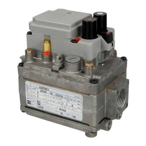
IST STEP ADJ.
PILOT ADJ.
REG. ADJ.
NO P.R.
