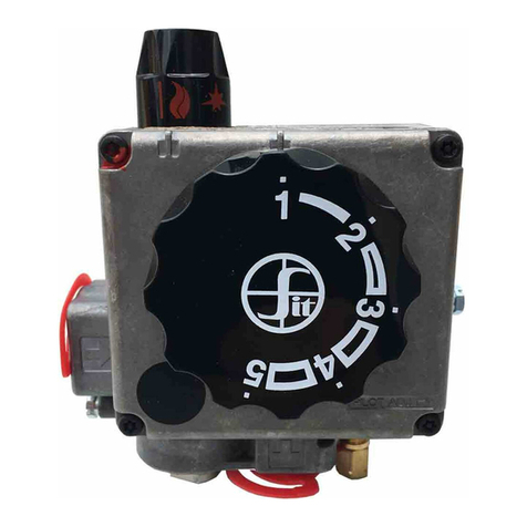
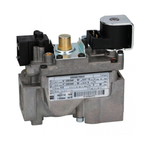
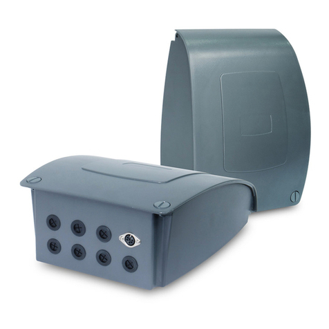
Sit 820 NOV A mV User manual

820 NOVA mV
MULTIFUNCTIONAL CONTROL FOR GAS
THERMOPILE POWER SUPPLY
THERMOELECTRIC SAFETY DEVICE
SERVO-CONTROLLED PRESSURE REGULATOR
SHUT-OFF SOLENOID VALVE
SIT Group
PIN 63AP7060/2
fire-parts.com

MAIN FEATURES
Multifunctional control with
shut-off solenoid valve
powered by a thermopile: an
external power supply is not
required. Fitted with:
thermoelectric safety device,
single control knob (off, pilot,
on), restart interlock against
improper operation, servo-con-
trolled pressure
regulator, and shut-off
solenoid valve with on/off gas
flow control.
Step ignition device on
request.
SINGLE-KNOB
MULTIFUNCTIONAL CONTROL
Thermopile power supply.
Three position (off, pilot, on) control knob.
Thermoelectric flame failure device with restart interlock.
Near-silent automatic shut-off valve.
Servo-controlled pressure regulator.
Step ignition device (optional).
Main gas flow manual adjustment device (on request).
Pilot outlet with gas flow restrictor.
Inlet and pilot filters.
Inlet and outlet pressure test points.
Threaded gas inlet and outlet with provision for flange connection.
Connection for pressure regulator / combustion chamber compensation.
820 NOVA mV is suitable for installation on boilers,
catering equipment, furnaces and radiators where
complete independance from the external electricity
mains supply is required.
Data refer to EN 126
fire-parts.com

TECHNICAL DATA
DESCRIPTION
THERMOPILE POWER SUPPLY
Use two-wire thermopile
Voltage with open circuit > 370 mV
Voltage with closed circuit > 145 mV
Resisistance of the coil 12.2ohm
8 Outlet pressure test point
9 Actuating solenoid valve
10 Pilot outlet
11 Main gas outlet
12 Holes (M5) for fixing flanges
13 Supplementary valve body fixing
points
14 Connection for pressure regulator /
combustion chamber compensation
15 Thermopile and thermostat
connection
1 Control knob
2 Main gas flow manual adjustment
device
3 Adjustment screw for gas flow
to the pilot
4 Thermocouple connector
5 Alternative thermocouple connector
6 Provision for accessories support
bracket
7 Inlet pressure test point
• Gas connections: Rp 1/2 ISO 7 (1/0 3/8” on request)
• Installation position: any position
• Gas families: I, II and III
• Maximum gas
inlet pressure: 60 mbar
• Outlet pressure
setting range: 3...30 mbar (20...50 on request)*
• Working temperature
range: 0...70 °C
• Pressure regulator: Class B
• Automatic solenoid
valve: Class D (Class C on request)
*
Versions without manual gas flow adjustment device
Data refer to EN 126
7 8 9
6
10
11
21 34
15
12
513
14
fire-parts.com

DIMENSIONS
FLOW RATE AS A FUNCTION OF PRESSURE DROP
18
24 41 70,5
25,5
30
50,5
12
36,5
AE
P
I
L
O
T
102
13
30
°
18
29 58
18
77
137
126
Rp 3/8 "
Rp 3/8 "
66,4
35
120,5
5127
36,5 94112
Rp 1/2 "
Rp 1/2 "
TP TH TP TH
3,5
TP TH TP TH
29
18
1
CLASS D
I Family (d = 0.45) Q = 7.5 m3/h ∆p = 5 mbar
II Family (d = 0.6) Q = 6.5 m3/h ∆p = 5 mbar
III Family (d = 1.7) Q = 8.1 kg/h ∆p = 5 mbar
CLASS C
I Family (d = 0.45) Q = 5.3 m3/h ∆p = 5 mbar
II Family (d = 0.6) Q = 4.6 m3/h ∆p = 5 mbar
III Family (d = 1.7) Q = 5.8 kg/h ∆p = 5 mbar
0510
Q [m3/h d=0.6]
4
2
6
8
10
∆p [mbar]
CLASS D
CLASS C
fire-parts.com

Pilot flame ignition
Depress and turn the control knob to the pilot position .
Depress the button and ignite the pilot flame while keeping the knob fully
depressed for a few seconds (fig. 1).
Release the knob and check that the pilot flame stays lit. If it goes out, repeat the
ignition operation.
Main burner ignition
Depress and turn the control knob to the “on” position (fig. 2).
When the automatic solenoid valve is energized, gas passage to the main burner is
opened.
Valves with step ignition devices reach the maximum flow after about 10 seconds.
Pilot position
To keep the main burner closed and the pilot flame lit, depress and turn the control
knob to the pilot position .
Turning off
Depress and turn the control knob to the “off” position (fig. 3).
Caution: the restart interlock device prevents ignition of the appliance until the
flame failure device has stopped gas flow. At the end of this period (after closing
the magnet unit) it is possible to carry out the re-ignition operation.
REGULATED FLOW RATE IN ACCORDANCE WITH EN 88
Inlet pressure range
Gas type
Nominal Max. Min.
2H 20 25 17
2L 25 30 20
Outlet pressure tolerance +10%...-15%
fig. 1
OPERATION
fig. 2
fig. 3
CLASS D
Inlet pressure range
Gas type
Nominal Max. Min.
2H 20 25 17
2L 25 30 20
Outlet pressure tolerance +10%...-15%
CLASS C
6 8 10 12 14 16 18
0
Q = [m3/h d=0.6]
Pu [mbar]
2
4
6
8
10
12
14
2L
2H
6 8 10 12 14 16 18
0
Q = [m3/h d=0.6]
Pu [mbar]
2
4
6
8
10
12
14
2L
2H
fire-parts.com

INSTALLATION
Main gas connection
The connection is made using gas pipes with Rp 1/2 ISO 7 threading. Torque: 25 Nm.
If, alternatively, flanges (available on request) are used, first screw the pipes onto the
flanges and then the flanges to the valve. Recommended torque for the flange fixing
screws: 3 Nm.
Connection to the pilot burner
Pipes with Ø 4 mm, Ø 6 mm or Ø 1/4 can be used. Use a nut and olive of appropriate
dimensions. Tighten the nut to 7 Nm torque.
Connection to the combustion chamber
Pressure regulator / combustion chamber compensation is possible when the latter is
pressurized (see figure).
Use the special SIT hose connectors for this purpose. Torque: 1 Nm.
Electrical connections
Use the special connectors for connection to the thermopile and to the thermostat.
Make the connections in accordance with the plan below and in accordance with the rules
for the appliance.
The electrical safety cut-off devices (for example, the flame failure device, limit
thermostat, and the like) must cut off the power supply to the thermoelectric circuit of the
safety magnet unit.
Caution: after making the connections, check gas tightness.
I
L
O
T
TP TH TP TH
P
WIRING PLANS
6
4
2
810 12
AE
P
I
L
O
T
TP TH TP TH
TP = thermopile
TH = thermostat
pilot burner
room thermostat
fire-parts.com

SETTINGS AND ADJUSTMENTS
Measurement of the inlet and outlet pressure
The inlet and outlet pressures of the gas can be
measured by unscrewing the provided test point
sealing screws.
Replace screws with 2.5 Nm torque.
Outlet pressure adjustment
Versions without manual gas flow adjustment
device (fig. 1).
Remove the protective plug (A), and screw in the
adjustment screw (B) to increase the outlet pressure
or screw it out to reduce it. Having made the
setting, fit the plug (A) flush.
Versions with manual gas flow adjustment device
(fig. 2).
The adjustment is made by turning the knob (E) on
which the symbol corresponds to the maximum
pressure to the burner and corresponds to the
minimum pressure. Actuation of this knob is
independent from actuation of the control knob.
Overriding the pressure regulator
Replace the plug (A), the adjustment screw (B) and
the spring (C) with the accessory (D), code
0.907.037. Torque: 1 Nm.
Gas flow-rate adjustment to the pilot
Screw in the associated screw to reduce the flow or
unscrew it to increase flow.
Overriding gas flow-rate adjustment to the pilot
It is sufficient to screw the adjustment screw in
flush and then screw it out two complete turns.
Changing the gas family or group
Check suitability for use with the gas family or
group of interest.
Following the instructions given above, adjust the
outlet pressure to the values indicated in the
instruction booklet of the appliance.
If required: override the pressure regulator and gas
flow adjustment to the pilot.
CAUTION:
Check tightness and efficiency and seal the
adjustment devices.
Implement the provisions in the Use and Maintenance
manual - code 9.956.820 - for installation, adjustment and use.
C
E
B
A
D
Fig.1 -
Outlet pressure adjustment
Versions without manual gas flow adjustment device
Fig.2 -
Outlet pressure adjustment
Versions with manual gas flow adjustment device
fire-parts.com

820 NOVA mV
Multifunctional control
for gas appliances
without electrical power
supply.
9.955.921 R01GRAPHIC DESIGN BY START - PD - ITALY
SIT La Precisa
Viale dell'Industria 31/33 35129 PADOVA - ITALY
Tel. 049/8293111 - Fax 049/8070093 - Telex 430130 SITEC I
fire-parts.com
Table of contents
Other Sit Controllers manuals
