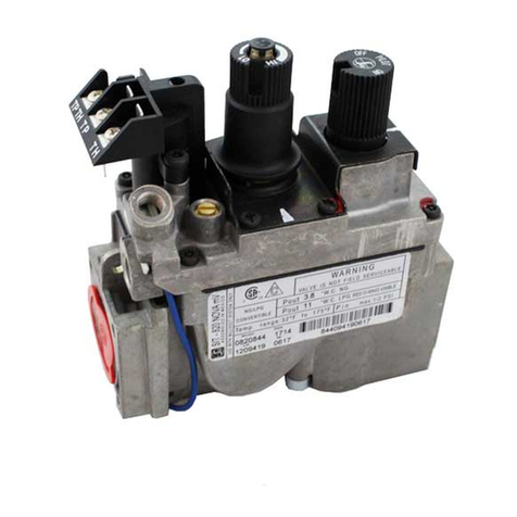
Sit PROFLAME DFC Technical manual

9.957.061 00
PROFLAME DFC CONTROL BOARD
USE AND INSTALLATION INSTRUCTIONS
Read the instructions before use.

2
IMPORTANT
The Proflame DFC, is the flame ignition and control board, part of the Proflame System, which can
be made of these elements:
• Standalone Proflame system
o Proflame DFC: the flame ignition and control board
o Proflame DFC main wirings
o Proflame pilot assembly
o Proflame 88# gas valve
o Proflame power supplies
• Remotely controlled Proflame system
o Proflame DFC: the flame ignition and control board
o Proflame DFC main wirings
o Proflame pilot assembly
o Proflame 88# gas valve
o Proflame GT*Transmitter
o Proflame GT*Receiver
o Proflame GT*main wirings
o Proflame GT Fan Control Module, or power supplies
o 540 split flow valve
in which the “#” character will be:
- “0” if a not modulating, or manual knob modulating valve is used,
- “5” if an electrical modulation valve is used,
- "6" if a manual knob modulating valve is used,
and the “*”string will be the composition of the following characters:
- “blank” if a not modulating, or manual knob modulating valve is used,
- “M” if an electrical modulation valve is used,
- “F” if the Fan Control Module peripheral is used, this will also supply power to the whole
system,
- “S” if the Split Flow Valve is used.

3
INTRODUCTION
The Proflame DFC (Digital Fireplace Control) board is a device that allows the automatic ignition
and pilot flame supervision, to command the functions of a hearth appliance.
It’s configured to control the ON/OFF main burner operation, giving the choice of both IPI
(intermittent pilot ignition), and CPI (continuous pilot ignition) modes.
The Proflame DFC board controls and connects directly to an automatic valve of the Proflame
880, and 885 families using low electric power.
The power supply could come from an AC/DC wall adapter, from a 4 AA battery pack, or from
both. This gives the capability to work both as a full battery, or a battery backup system.
If a remotely controlled Proflame system is used, no dedicated power to the DFC is needed, as
the supply comes through the wiring connections.
PROFLAME DFC BOARD GENERAL CONNECTIONS
See Fig. 1.
FLAME
SENSOR
ROD
DIAGNOSTIC
/BUZZER
SPARK ROD
PILOT GROUND
+
+
-
-7VDC STABILIZED
SUPPLY
4 X 1.5 BATTERY
SET
MAIN ON / OFF
IPI / CPI MODE
VALVE BODY GROUND
EV2
EV1
Fig. 1
CN4
CN3 CN2 CN1
CN0
CHASSIS
9 8 7 6 5 4 3 2 1
1
2
3
4

4
DFC control board
Supply voltage DC IN: 7Vdc - 200mA max (Class 2 power supply)
BB IN: 6Vdc - 200mA max (four 1.5V size AA batteries)
Ambient temperature ratings -18 .. +80 °C (0 .. +176 °F)
Spark voltage >15kV
Spark energy >0,7mJ
Spark frequency 1Hz
Tested gas types the system has been tested for NG, and LPG gas
types/mixtures
Pilot ignition source Intermittent/Continuous
Please refer both to the Gas Valve, and to the Pilot Assembly User and Installation manuals for:
- the recommended gas input for the pilot burner;
- the electrical specifications;
- the operating temperatures and the components that have to be directly exposed to flame.
TECHNICAL DATA
GENERAL CONNECTION & SET-UP GUIDE FOR PROFLAME DFC BOARD
General Connection & Set-Up Guide for Proflame DFC board:
1. The DFC board should be placed in a low temperature area of the appliance.
2. Connect the pilot and control valve as indicated in fig. 2. (Stand Alone System, No Remote)
3. Connect the pilot, control valve and remote system as indicated in fig. 3. (DFC with Remote
System & Wall AC Adaptor)
4. Connect the pilot, control valve and remote system as indicated in fig. 4. (DFC with Remote
System & Fan Control Module Power)

5
FUNCTIONS
Preliminary check of a Standalone Proflame system
Before applying any power supply to the DFC board please verify that the electrical connections are
in accordance to Fig. 2
Initializing the System for the first time
Set the main burner flame ON/OFF command to its OFF position.
If installed, set the pilot flame mode selector to its IPI position.
If provided, install the 4 AA batteries into the battery holder, and respect the polarity indicated on the
battery holder silkscreen. Connect the battery holder to the DFC’s main wiring harness.
Connect the AC/DC wall adapter to the DFC’s DC-jack connector on the main wiring harness, and
plug it into the wall mains supply.
Orange Green
Red
Black
880/886 Proflame
Battery
Holder
Chassis
connection
120 Vac INPUT
7 Vdc STABILIZED
SUPPLY OUTPUT
ON / OFF CPI / IPI MODE
ON/OFF IPI/CPI
BATTERY
DC SUPPLY
VALVE
GROUND
DFC
Fig. 2: electrical connections of standalone Proflame system

6
PRELIMINARY CHECK OF A REMOTELY COMMANDED SYSTEM
Before applying any power supply to the system, check that the electrical connections are
according:
• to Fig. 3 for Proflame system with the electrical modulation, and/or the fan control module,
and/or the split flow valve
• to Fig. 4 for Proflame system with the electrical modulation, and/or the AC/DC power
supply, and/or the split flow valve
REMOTE
REMOTE
120V OUT
Receiver 14
Pin Connector
Split Flow
Pilot
Pink
Blue
CPI / IPI MODE
MOTOR
IPI/CPI
RECEIVER
FCM-COM
SPLIT FLOW
ON / OFF
TH
TPTH
DC SUPPLY
DC SUPPLY
GROUND
Orange Green
Chassis
connection
885 PROFLAME
Fig. 3
Fig. 4
REMOTE
REMOTE
Receiver 14
Pin Connector
Split Flow
Pilot
Pink
Blue
CPI / IPI MODE
120 Vac INPUT
7 Vdc STABILIZED
SUPPLY OUTPUT
MOTOR
IPI/CPI
RECEIVER
DC SUPPLY
SPLIT FLOW
ON / OFF
TH
TPTH
DFC SUPPLY
DC SUPPLY
GROUND
885 PROFLAME
Orange Green
Chassis
connection
Remote control
Remote control

7
INITIALIZING THE SYSTEM FOR THE FIRST TIME
Place the 3 position slider switch in the “OFF” position as indicated in Fig. 5.
Install the 4 AA batteries into the receiver battery bay. Note the polarity of the batteries and insert
them into the battery bay as indicated on the Battery cover (+/-).
Using the end of a paper clip, or other similar object, press the button through the hole marked
“PRG” on the Receiver front cover Fig. 5. The Receiver will “beep” three (3) times to indicate that it is
ready to synchronize with a Transmitter. Install the 3 AAA type batteries in the Transmitter battery bay,
located on the base of the Transmitter. With the batteries already installed in the Transmitter, push the
ON button. The Receiver will “beep” four times to indicate the Transmitter’s command is accepted,
and the Receiver is now set to the particular code of that Transmitter.
Push the OFF button on the Transmitter. The Receiver will “beep” two (2) times to indicate the
Transmitter’s command is again accepted.
Place the 3 position slider switch on the Receiver at the “Remote” position as indicated in Fig. 5.
If installed, turn ON the fan control module, switching it to the ON (I) position.
The system is now initialized.
LOW BATTERY POWER DETECTION
Since the batteries that are mounted in the remote receiver also supply the DFC ignition board, the
endurance of the system batteries depend on various factors:
- the battery pack function, full battery operation, or battery backup operation,
- the chemistry type (normal, alkaline), and the quality of the batteries,
- the number of ignitions of the appliance,
- the number of changes to the room thermostat set point.
- the temperatures at which the batteries are exposed,
- the supervised pilot flame quality,
- etc.
When the Receiver batteries are low, no “beep” will be emitted from the Receiver when it receives an
ON/OFF command from the Transmitter. This is an alert for a low battery condition for the Receiver.
PRG Key
3 Position Slider
14 PIN terminal
Fig. 5

8
When the batteries are replaced the “beep” will be emitted from the Receiver when the ON/OFF key
is pressed (see Initialization of The System).
- in IPI (intermittent pilot ignition) mode the board upon receiving a main burner
command operation, will start its functional cycle from a completely shut OFF flame
state, by initially igniting the pilot flame, and keeping it under supervision before and
during the main burner operation;
- in CPI (continuous pilot ignition) mode, the board will start by initially igniting the pilot
flame, and keeping it permanently under supervision, then the board will be able to
rapidly serve a main burner command operation.
STANDARD IDENTIFICATION: ANS Z21.20, Automatic Ignition Systems.
WARNING
Fire Hazard. Can cause severe injury or death.
The Remote Receiver causes ignition of the appliance. The appliance can turn on suddenly.
Keep away from the appliance burner when operating the remote system or activating manual
bypass of the remote system.
WARNING
All the parts of the system are not intended to operate in presence of water dripping, spraying,
rain, etc. that could generate also by condensation or ice that melts, etc.. Otherwise means
shall be provided to protect all the components.
WARNING
Battery operated device.
Read the battery instructions before installing them into the system. Do not expose any battery,
or its holder, or a device in which batteries are installed, to a working temperature greater than
54°C / 129°F. Avoid battery overheating even if the working temperature of the device to which
the batteries are connected is reported to be greater than 54°C / 129°F. In case of overheating
the batteries will degrade their stored charge capacity, or leak corrosive liquids, or in bad
cases, develop hydrogen gas and explode.
CAUTION:
Label all wires prior to disconnection when servicing controls. Wiring errors can cause improper
and dangerous operation.
Ensure that high voltage carrying wires (i.e. the spark igniter wire) are laid down far away (i.e.
farther than 2,5cm – 1inch) from the electronic controlled devices.
CAUTION
Property Damage Hazard.
Excessive heat can cause property damage.
The appliance can stay lit for many hours.
Turn off the appliance if it is not going to be attended for any length of time.
Always place the Transmitter where children can not reach it.
The board reset from a volatile lock-out can be accomplished by the switching
action of a thermostat or a similar device on the command input.

9
APPENDIX
1. Command definitions
Pilot IPI / CPI switch Main Turn ON switch,
or state of the remote
control contact
Command reference
name
Commanded Fireplace
State
Opened, IPI Opened, remote
switch set OFF
Turn-OFF Flames OFF
Opened, IPI Closed, remote switch
set ON
Turn-ON Pilot + Main burner
flames ON
Closed, CPI Opened, remote
switch set OFF
Pilot-ON Pilot flame ON
Closed, CPI Closed, remote switch
set ON
Turn-ON Pilot + Main burner
flames ON
2. DFC board operation
2.1 IPI operation mode
The IPI operation mode means Intermittent Pilot Ignition. In this mode the CPI/IPI switch
must be left opened.
In this mode the board can be commanded to follow the ignition sequences for both the
Pilot, and the Main Burner Flame as follows:
- assume to start from a completely shut OFF fireplace, with IPI Mode initially set,
- a Turn-ON command will initiate, and bring to completion the Pilot Flame ignition
sequence, then the Main Burner Flame ignition sequence is automatically commanded
after the Pilot Flame is detected steadily established,
- a Turn-OFF command will determine the gas valve shutdown so both the Pilot
Flame, and the Main Flame will extinguish.
2.2 CPI operation mode
The CPI operation mode means Continuous Pilot Ignition. In this mode the CPI/IPI switch
must be left closed.
In this mode the board immediately completes the ignition sequence for the Pilot Flame,
and then remains with the Pilot Flame ON, waiting for a command to ignite the Main Burner
Flame as follows:
- assume to start from a completely shut OFF fireplace, with CPI Mode initially set,
- the Pilot Flame ignition sequence is initiated, and brought to completion, the Pilot
ON state is maintained,
- a Turn-ON command will initiate the Main Burner Flame ignition sequence,
- a Pilot-ON command will shut down the Main Burner portion of the gas valve so
the Main Flame will extinguish, leaving a permanent Pilot ON flame.
A Turn-OFF command is only possible by setting the IPI/CPI switch back to IPI position.
2.3 Details about the ignition sequences for the Pilot Flame
For the DFC board the Pilot flame is the supervised safety flame: it is used as the ignition
flame source for the more powerful Main Burner Flame.
2.3.1 Turn-OFF
In this state, the gas to the appliance is cut-off by the gas valve.
In this state the DFC board will wait for a command.

10
2.3.2 Pilot-ON
In this state the Pilot Flame sequence is executed, and it will lead the system to a
continuous Pilot flame condition through these steps:
- if the previous state was Turn-OFF,
the Pilot Flame detection is turned ON,
a Pilot Flame check sequence is completed to avoid parasitic flame detection,
the spark generator is activated,
the Pilot gas valve solenoid is set to open the gas flow to the pilot hood,
in the mean time the Main Burner gas valve solenoid is set to close the gas flow;
- if the previous state was Turn-ON,
the Pilot Flame detection is maintained ON,
the Pilot gas valve solenoid is set to keep opened the gas flow to the pilot hood,
in the mean time the Main Burner gas valve solenoid is set to close the gas flow.
2.3.3 Turn-ON
In this state both the Pilot, and the Main Burner Flames sequences are executed, and it
will lead the system to a fireplace completely lit:
- if the previous state was Turn-OFF,
the Pilot Flame detection is turned ON,
a Pilot Flame check sequence is completed to avoid parasitic flame detection,
the spark generator is activated,
the Pilot gas valve solenoid is set to open the gas flow to the pilot hood,
in the mean time the Main Burner gas valve solenoid is set to close the gas flow,
the Pilot Flame is let to stabilize,
the Main Burner gas valve solenoid is set to open the gas flow;
- if the previous state was Pilot-ON,
the Pilot Flame detection is maintained ON,
the Pilot gas valve solenoid is set to keep opened the gas flow to the pilot hood,
in the mean time the Main Burner gas valve solenoid is set to open the gas flow.
2.3.4 Lockout state definition
A lockout state is reached when an ignition error occurs, in any case the lockout on this
board is volatile, this means that the lockout state will remain set in memory as long as the
power supplies are applied.
This could mean both an anomalous flame detection, and/or too many unsuccessful
ignition tries.
This state is a safe condition for the appliance, and is entered automatically by the DFC
board.
When the DFC gets into lockout state:
1. both the Pilot, and the Main Burner solenoids in the gas valve are de-energized;
2. a diagnostic code is sent through the diagnostic port: if a signalling device is
applied to the port the signal could be heard or seen by the user and recognized
through a numeric code.
Having no diagnostic mean, the symptom of a lockout could be verified on a not
responding board by trying to set the Pilot-ON command in CPI mode, because
the board will not ignite the pilot flame;
3. the DFC board will ignore any command setting, and remain into Turn-OFF state,
unless the unlock command sequence is met.
The causes of lockout must be investigated under safe conditions by the user and / or the
service personnel.
The return of the system to the normal operation can be done releasing the DFC board
from lockout in one of the following ways:

11
- turning all the system power supplies OFF for a defined number of seconds, and
then restoring a power supply back ON,
- a complete manual reset sequence: since the command reset sequence can be
commanded through a remote receiver the lockout can be defined as Soft Lockout.
The return of the system to normal operation must be checked under safe conditions by
the user and / or service personnel.
2.3.4.1 Lockout reset sequence
The command sequence to unlock the DFC board from the lockout state is the same
whatever the command source is installed on the Main Turn ON command input.
Standalone system, Fig. 2:
- act on the Main Turn ON switch to put it into OFF position for at least 2s,
then put it into ON position for at least 2s,
then the DFC board will execute the internal tests and begin the ignition sequences.
Remotely commanded system, Fig. 3, Fig. 4:
- act on the Proflame GT* receiver slide switch:
set it to OFF position for at least 2s,
then set it to ON position for at least 2s,
then the DFC board will execute the internal tests and begin the ignition sequences,
or:
- act on the Proflame GT* transmitter once the GT* receiver slide switch is set to
REMOTE position:
turn OFF the flame request by the transmitter and wait in OFF state for at least 2s,
then turn ON the flame request for at least 2s,
then the DFC board will execute the internal tests and begin the ignition sequences:
the proper acknowledgement of the transmitted OFF/ON commands should be
heard through the GT* receiver beeps.
The IPI/CPI switch will not operate to unlock the board: it could be used anyway to test if
a properly supplied DFC board is in lockout because setting the switch to CPI position,
the DFC will not initiate the Pilot Flame ignition.
2.4 Diagnostics
The diagnostic signalling could be provided through these diagnostic means installed on
the board:
1. visually, through a LED annunciator, or
2. acoustically, through a piezoelectric buzzer, or
3. through a dedicated high speed diagnostic port.
2.4.1 Real-time diagnostic messages – LED/buzzer indications
If the optional signalling device is connected to DFC board on CN0, the following
diagnostic/alert signals could be interpreted in case of a system anomaly: obviously any
indication is provided until a reliable level of power supply gets to the DFC board.
The following codes appear in the reported order of priority:

12
2.5 Special sequences: automatic safety restart
Whatever the DFC board state is in, it will execute automatically a Turn OFF command
within 24 hours of continued pilot flame ignition.
This command sequence will led the system to OFF state to verify the correct functioning
of safety means.
After the turn OFF sequence is completed, the FBC board will re-execute the latest
command.
3. DFC board behaviours under abnormal, or particular conditions
3.1 A Pilot Flame is revealed before the Pilot Flame ignition sequence
The system will not proceed to the gas ignition until a pilot flame is detected lit
upon the start-up for the Pilot Flame ignition sequence.
3.2 No pilot flame is established during the pilot ignition sequence
If no pilot flame is sensed during the pilot flame ignition sequence, the system will
retry for a predefined number of times.
A waiting period is introduced between retries to purge the unburned gas from the
appliance combustion chamber.
After the last try with no successful ignition, the system will shut down the gas, and
enter a VOLATILE LOCKOUT.
3.3 Pilot loss of flame in Pilot-ON, or in Turn-ON states
If a loss of the pilot flame signal is sensed during a state in which the pilot flame
should remain lit, the system will proceed to restore the pilot flame ignition, and will
close the main burner gas valve, and will start a timer to count the time from the
flame failure.
If too many repeated pilot flame signal losses are detected within the timer
expiration, the system will shut down the gas, and enter a VOLATILE LOCKOUT.
If the pilot flame robustness timer elapses with the number of pilot flame losses
within the predefined limit, the ignition sequence will continue normally.
Diagnostic signals
Code Lockout
state
Parasitic
pilot
flame
detected
at startup
DFC power supply
Number
of
LED
Flashes
or Buzzes
Pause
time
between
signals
C3 Yes Doesn’t
care Enough power supply to signal 3
Some
seconds
C2 No Yes Enough power supply to signal 2
C1 No No
Enough power supply to signal,
and the battery level is between
the predefined minimum power
supply range for the battery
1
C0 No No
Enough power supply for
operation, battery voltage at
reliable level or absent
none

13
3.4 Behaviour of the DFC board in relation to the power supplies
3.4.1 Operation on dropout DC supply condition: the battery backup
The battery supply is provided to connect to the system upon a permanent, or
momentary AC line voltage loss that will make the DC input power supply to drop.
The DFC will continue operation in backup, so without apparent interruption, if
the batteries are installed in the system, and if the battery charge level is into the
specified range.
If also the battery voltage drops too much, the pilot flame start-up could become
impossible and the system will proceed to shutdown.
If a low battery level is detected connected to the DFC board, it will signal this
anomaly through the diagnostic BUS signalling device.
3.4.2 Operation upon the restoration of the DC supply conditions, or replacement of the
batteries
If the AC line voltage comes back again, or the batteries are replaced in the
system with new ones, the system will re-execute the command that was last set at
its command inputs.
This means that if a thermostatic, or a manual switch is in closed position on the
Turn-ON switch input, or the IPI/CPI switch is in CPI position, the DFC board will
initiate the selected flame ignitions.
This is due to the fact that the DFC board assumes the command switches state
as an operational mode assertion principle, and is not able to distinguish a closed
contact as closed intentionally, or automatically.

14
This page is intentionally left blank

15
This page is intentionally left blank

Table of contents
Other Sit Controllers manuals
Popular Controllers manuals by other brands
digitalview
digitalview ALR-1920-SDI instructions
Sound Sation
Sound Sation Scenemaker 1216 Pro USB user manual
wattstopper
wattstopper LMRC-111 quick start guide
All LED
All LED DynColor DC300-RL-RGB-Rope user guide
Atronix
Atronix X45/10 Installation and operating instructions

AstroGadget
AstroGadget DobsonDream user guide
Hobby-Wing
Hobby-Wing 8A UBEC user manual
superbrightleds
superbrightleds LDRF-RGB8-TC3B instruction sheet
BOSSCO
BOSSCO EA218 Series quick start guide

System air
System air TControl POD glass EC Installation and maintenance manual

InnoMedia
InnoMedia InnoMedia ESBC 9578-4B Quick install guide
Delta
Delta 29FWC-100E instruction manual
