Sit TRASCO GRMP Series Operating instructions

SIT S.p.A. Viale A. Volta, 2 - 20090 Cusago (MI) - Italy
TRASCO®Couplings
OPERATING AND MAINTENANCE MANUAL

INDEX Pag.
1GENERAL INFORMATION 4
1.1 PURPOSE OF THE DOCUMENT 4
1.2 PROPER USE 4
1.3 WARNING SYMBOLS FOR SAFETY 4
1.4 GENERAL ADVICE IN CASE OF DANGER 5
1.5 REFERENCE LAWS AND STANDARDS 5
2CHARACTERISTICS OF TRASCO®COUPLINGS 5
2.1 HUBS 6
2.1.1 GRMP SERIES HUBS 6
2.1.2 GRMALU SERIES HUBS 8
2.1.3 GRB SERIES HUBS 8
2.1.4 GRS SERIES HUBS 10
2.1.5 GRF SERIES HUBS 11
2.1.6 HUBS MACHINING 13
2.1.7 POSITION AND SIZE OF THE SETSCREW 14
2.2 ELASTIC SPIDER 15
2.2.1 ELASTIC SPIDER PERFORMANCE 16
2.3 COUPLING MISALIGNMENTS 17
3STORAGE 17
4ASSEMBLING 18
4.1 GRMP COUPLING ASSEMBLY 18
4.2 GRB COUPLING ASSEMBLING 20
4.2.1 TAPER BUSH MOUNTING 20
4.2.2 TAPER BUSH DISASSEMBLING 21
4.3 GRS COUPLING ASSEMBLING 21
44 GRF COUPLING ASSEMBLING 22
4.4.1 FLANGE-FLANGE VERSION 22
4.4.2 SHAFT-FLANGE VERSION 23
4.4.3 SHAFT-SHAFT VERSION 24
5ATEX ANNEX 25
5.1 ATEX ZONE CLASSIFICATION 25
5.2 ATEX EQUIPMENT CLASSIFICATION 26
5.3 APPROPRIATE USE OF TRASCO®COUPLINGS IN ATEX ZONES 26
5.3.1 GAS TEMPERATURE CLASSES FOR GROUP II EQUIPMENT 26
5.3.2 TEMPERATURE CLASSES FOR GROUP I EQUIPMENT 26
5.4 MARKING 27
5.4.1 COMPLETE MARKING 27
5.4.2 COMPACT MARKING 27
5.5 HUB MACHINING IN ATEX ENVIRONMENT 28
5.6 ELASTIC SPIDER CHECK 28
5.7 INTERNAL MANUFACTURING CHECK 29
5.8 STARTING 29
5.8.1 PROTECTION DEVICES FOR COUPLINGS IN HAZARDOUS ATMOSPHERES 30
5.8.2 ELECTRICAL CONTINUITY 30
5.9 DECLARATION OF CONFORMITY 31

INDEX OF TABLES Pag.
TABLE 2.1 TRASCO®: HUBS MATERIALS 6
TABLE 2.2 DIMENSIONS TRASCO®GRMP 7
TABLE 2.3 TRASCO®GRMP LENGTHS 7
TABLE 2.4 DIMENSIONS TRASCO®GRMALU 8
TABLE 2.5 DIMENSIONS TRASCO®GRB 9
TABLE 2.6 DIMENSIONS TRASCO®GRS 10
TABLE 2.7 DIMENSIONS TRASCO®GRF 11
TABLE 2.8 DIMENSIONS TRASCO®GRF 12
TABLE 2.9 TRASCO®: POSIZIONE GRANO DI FISSAGGIO 14
TABLE 2.10 ELASTIC SPIDER PERFORMANCE 16
TABLE 2.11 TRASCO®: MISALIGNMENTS 17
TABLE 4.1 QUOTE M 19
TABLE 4.2 GRANI BUSSOLE CONICHE 20
TABLE 4.3 GRF SCREWS 22
TABLE 5.1 ATEX ZONE CLASSIFICATION 25
TABLE 5.2 ATEX GROUPS AND CATEGORIES CLASSIFICATION 26
TABLE 5.3 GAS TEMPERATURE CLASSES 26
TABLE 5.4 QUOTE Z FOR CHECKING SPIDER WEAR 28
INDEX OF FIGURES Pag.
FIGURE 2-1 TRASCO®GRMP HUBS 6
FIGURE 2-2 TRASCO®SERIES GRB 8
FIGURE 2-3 TRASCO®SERIES GRS 10
FIGURE 2-4 TRASCO®GRF HUBS 11
FIGURE 2-5 TRASCO®GRF C HUBS 12
FIGURE 2-6 PROCESSING TOLERANCE 13
FIGURE 2-7 SETSCREW POSITION 14
FIGURE 2-8 ELASTIC SPIDER 15
FIGURE 2-9 TRASCO®: MISALIGNMENTS 17
FIGURE 4-1 GRMP COUPLING 18
FIGURE 4-2 GRMP: MOUNTING 19
FIGURE 4-3 TYPES OF GRB 20
FIGURE 4-4 GRS INTERMEDIATE ELEMENT 21
FIGURE 4-5 FLANGE-FLANGE VERSION (CF/CFN) 22
FIGURE 4-6 SHAFT-FLANGE VERSION (CF/CFN) 23
FIGURE 4-7 SHAFT-SHAFT VERSION (CF/CFN) 24
www.sitspa.com TRASCO®- Operating and Maintenance Manual
114.01 - Rev. 3 - 24 April 2019 Approved by SIT S.p.A.
4
1 General information
1.1 Purpose of the document
1.2 Proper use
1.3 Warning symbols for safety
We recommend that you carefully read all the mounting instructions before installing the coupling, paying particular attention to the safety
instructions.
TRASCO®coupling is suitable for use in potentially explosive atmospheres. When using the coupling in hazardous areas, strictly observe
the special information and instructions regarding safety in the ATEX attachment.
The mounting instructions are part of the product; please keep them safe and close to the coupling.
They are available in electronic format on the website www.sitspa.com.
All the rights of this manual are reserved and are the property of SIT S.p.A.; therefore, its sale and reproduction without permission are
prohibited.
The purpose of this document is the description of the TRASCO®couplings, both in the standard version and in the version suitable for
use in potentially explosive environments in accordance with ATEX Directive 2014/34/EU.
All the indications are provided, so that it is properly dimensioned, stored and assembled.
As regards the couplings that have to work in potentially explosive environments, all the indications and standards for identifying the
installation areas for which the coupling is certified to operate in safe conditions are provided.
Before handling a SIT coupling for moving, installing, or performing maintenance, it is advisable to carefully read the mounting instructions.
Any kind of changes aren’t authorized except those expressly provided for in the operating and maintenance manual.
SIT assumes no liability for damage resulting from tampered material and, therefore, no longer original.
SIT reserves the right to make changes to the product; as a consequence, this manual will be updated. The technical specifications listed
in the operating and maintenance manual exactly match the state of the art at the time of printing.
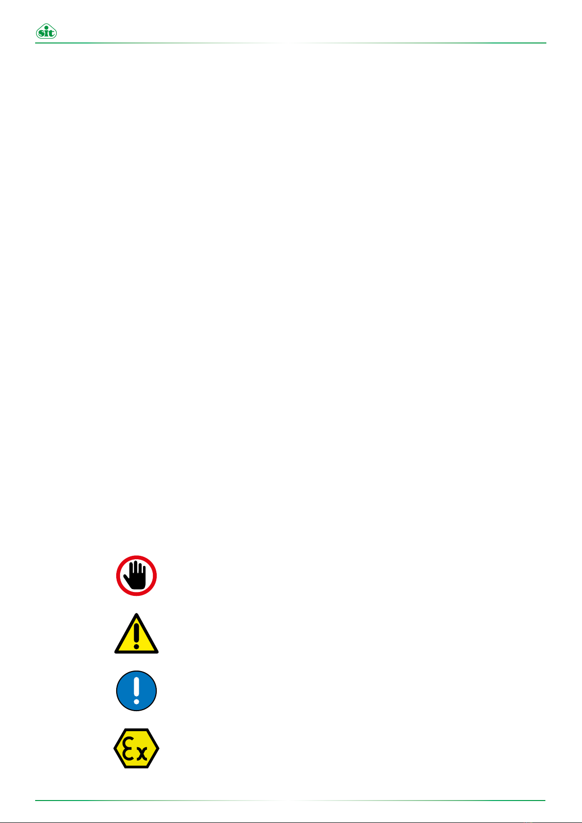
The warning symbols included in this manual alert the user to possible risks that may occur during handling, assembling and use of the
coupling.
It is necessary to pay particular attention to them.
STOP
DANGER Danger of injury to persons.
CAUTION Possible damages to the machine.
ATTENTION Important guidelines to follow.
PRECAUTION Hints about explosion protections.

www.sitspa.com TRASCO®- Operating and Maintenance Manual
114.01 - Rev. 3 - 24 April 2019 Approved by SIT S.p.A.
5
1.4 General advice in case of danger
1.5 Reference laws and standards
2 Characteristics of TRASCO®couplings
DANGER!
Every operation performed on the coupling, either with mounting
or maintenance, must be carried out with the machine not con-
nected to the power supply. Accidental contact with the rotating
parts can cause serious injury to the operator. It is recommended
to read these operating instructions to ensure safety.
STOP
• Affix proper warning signs around the machine
• Instruct the operator before giving permission to work on the coupling
• Operate on the coupling and on the transmission in safe conditions
• Make sure the machine power is disconnected before carrying out any operation
• Do not touch any moving part of the machine and wait until it stops completely
• Protect the coupling against accidental contact with protection devices
This evaluation was carried out in accordance with the provisions of the relevant laws, directives, standards mentioned below:
TRASCO®couplings are a flexible and constant-velocity coupling that ensures maximum performance with same overall dimensions. It
is very compact and allows a safe transmission of motion between the motor and the driven machine, absorbing shocks and torsional
vibrations. It also allows, through the elastic deformation of the elastic spider, to compensate for angular, radial and axial misalignments
due to small variations in length of the shafts. The hub teeth and spider profiles are designed so as to obtain a uniform pressure distri-
bution.
The elastic element is subject only to compression stress and does not induce any axial or radial stresses, providing the TRASCO®
coupling with great load capacity and durability. The coupling can be assembled both horizontally and vertically, and it correctly tolerates
load variations and reversals.
DIN 740/2 Reference standard for flexible couplings
ATEX DIRECTIVE 2014/34/EU Equipment and protective systems intended for use in potentially explosive atmospheres
ATEX GUIDELINES 2014/34/EU Guidelines to the application of Directive 2014/34/EU
EN 1127-1:2011 Explosion prevention and protection against explosion. Basic concepts and methodology
EN 13463-1:2009 Non-electrical equipment for potentially explosive atmospheres. Basic method and requirements
EN 13463-5:2011 Non-electrical equipment for potentially explosive atmospheres. Constructional safety "c"
The TRASCO®series is suitable for use in areas classified with the
presence of flammable gases, vapours and mists or combustible
dusts (Zone 1/21, category 2 GD).
It is designed and built in accordance with the ATEX Directive
2014/34/EU and in accordance with the following European stan-
dards:
• EN 1127-1:2011
• EN 13463-1:2009
• EN 13463-5:2011
This manual suits for next models
4
Table of contents
Other Sit Industrial Equipment manuals


