MiTAC TYAN S5565 User manual

http://www.tyan.com
1
S5565
Version 1.0
Copyright
Copyright © 2023 MITAC COMPUTING TECHNOLOGY CORPORATION. All rights
reserved. No part of this manual may be reproduced or translated without prior
written consent from MITAC COMPUTING TECHNOLOGY CORPORATION.
Trademark
All registered and unregistered trademarks and company names contained in this
manual are property of their respective owners including, but not limited to the
following.
TYAN®is a trademark of MITAC COMPUTING TECHNOLOGY CORPORATION.
Intel®is a trademark of Intel®Corporation.
AMI, AMI BIOS are trademarks of AMI Technologies.
Microsoft®, Windows®are trademarks of Microsoft Corporation.
Nuvoton®is a trademark of Nuvoton Technology Corporation.
Notice
Information contained in this document is furnished by MITAC COMPUTING
TECHNOLOGY CORPORATION and has been reviewed for accuracy and reliability
prior to printing. MITAC assumes no liability whatsoever, and disclaims any express
or implied warranty, relating to sale and/or use of TYAN®products including liability
or warranties relating to fitness for a particular purpose or merchantability. MITAC
retains the right to make changes to product descriptions and/or specifications at
any time, without notice. In no event will MITAC be held liable for any direct or
indirect, incidental or consequential damage, loss of use, loss of data or other
malady resulting from errors or inaccuracies of information contained in this
document.

http://www.tyan.com
2

http://www.tyan.com
3
Contents
Before you begin….................................................................................... 4
Chapter 1: Instruction ................................................................................ 5
1.1 Congratulations ................................................................................. 5
1.2 Hardware Specifications.................................................................... 5
1.3 Software Specifications ..................................................................... 7
Chapter 2: Board Installation..................................................................... 9
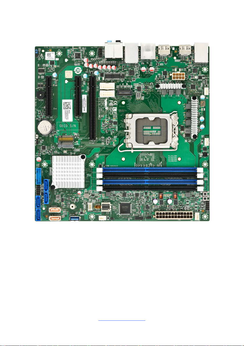
2.1 Board Image .................................................................................... 10
2.2 Block Diagram ................................................................................. 11
2.3 Mainboard Mechanical Drawing ...................................................... 12
2.4 Board Parts, Jumpers and Connectors ........................................... 13
2.5 LED Definitions................................................................................ 24
2.6 Installing the Processor and Heat sink ............................................ 25
2.7 Thermal Interface Material .............................................................. 30
2.8 Tips on Installing Motherboard in Chassis ...................................... 31
2.9 Installing the Memory ...................................................................... 33
2.10 Attaching Drive Cables .................................................................. 36
2.11 Installing Add-In Cards .................................................................. 37
2.12 Connecting External Devices ........................................................ 38
2.13 Installing the Power Supply ........................................................... 40
2.14 Finishing Up................................................................................... 40
Chapter 3: BIOS Setup ............................................................................. 41
3.1 About the BIOS................................................................................ 41
3.2 Main Menu....................................................................................... 43
3.3 Advanced Menu............................................................................... 44
3.4 Chipset Menu .................................................................................. 75
3.4 Security............................................................................................ 84
3.5 Boot ................................................................................................. 89
3.6 Save & Exit ...................................................................................... 91
3.7 MailBox ............................................................................................ 92
Chapter 4: Diagnostics............................................................................. 95
4.1 Flash Utility ...................................................................................... 95
4.2 AMIBIOS Post Code (Aptio) ............................................................ 96
Appendix I: How to recover UEFI BIOS ................................................ 103
Appendix II: Fan and Temp Sensors .................................................... 107
Glossary................................................................................................... 109
Technical Support .................................................................................. 115

http://www.tyan.com
4
Before you begin…
Check the box contents!
The retail motherboard package should contain the following:
1 x S5565 Motherboard
2 x SATA Cable
1 x M.2 Board Latch
1 x Rear IO Shield
1 x S5565 Quick reference guide
IMPORTANT NOTE:
Sales sample may not come with the accessory listed above.
Please contact your sales representative to help order accessory for your
evaluation.

http://www.tyan.com
5
Chapter 1: Instruction
1.1 Congratulations
You have purchased the powerful TYAN® S5565 motherboard, based on the
Intel®Q670 Chipset. The S5565 is designed to support single Intel®12th Gen.
Core i9/i7/i5/i3 processor, and up to 128GB of DDR4 unbuffered non-ECC
UDIMM 3200 memory. Leveraging advanced technology from Intel®, the S5565
is capable of offering scalable 32 and 64-bit computing, high-bandwidth memory
design, and lightning-fast PCI-E bus implementation.
The S5565 not only empowers you in today’s demanding IT environment but also
offers a smooth path for future application upgradeability. All of these rich feature
sets provides the S5565 with the power and flexibility to meet demanding
requirements for today’s IT environments.
Remember to visit the TYAN® website at http://www.tyan.com. There you can
find all the information on all TYAN®products as well as all the supporting
documentation, FAQs, Drivers and BIOS upgrades.
1.2 Hardware Specifications
TYAN S5565 (S5565AG2NR)
Processor
Q'ty / Socket Type (1) LGA1700
Supported CPU Series Intel Core i9/i7/i5/i3 Processors / 12 Gen.
Thermal Design Power
Wattage
Max up to 125W (TDP)
Chipset PCH Intel Q670
Memory
Supported DIMM Qty (4) DIMM slots
DIMM Type / Speed DDR4 Unbuffered non-ECC UDIMM
3200
Capacity Up to 128GB / *Follow latest Intel DDR4
Memory POR
Memory channel 2 Channels per CPU
Memory voltage 1.2V
Expansion Slots PCIe (2) PCIe Gen.3 x8 slots ( w/ x4 link) /
(1) PCIe Gen.3 x16 slot
LAN
Q'ty / Port (1) GbE + (1) 2.5GbE
Controller Intel I225V / Intel I219 (Intel AMT
support)
Storage SATA
Connector (2) SATA-DOM / (4) SATA
Controller Intel Q670
Speed 6Gb/s

http://www.tyan.com
6
RAID VMD RAID 0/1/10/5 (Intel RST/VMD)
Storage NVMe Connector (M.2) (2) 22110/2280 (by PCIe Gen.3 interface)
Graphic Display
Port
Connector type (3) Display ports
Resolution Up to 4096X2304 @60Hz
Chipset Intel Processor Graphics
Input /Output
USB (1) USB2.0 header / (1) USB3.2 Gen.1
header / (2) USB2.0 ports / (4) USB3.2
Gen.1 ports
RJ-45 (1) GbE port + (1) 2.5GbE port
Front Panel (1) 2 x 5 header
COM (2) header
Audio (1) 5 holes Audio Jack+SPDIF fiber
connector
SATA (4) SATA-III connectors / (2) SATA-DOM
connectors
Power (1) ATX 24-pin / (1) 2x4 Power input
connectors
Display port (3) Display ports
TPM (Optional) TPM Support Please refer to our TPM supported list.
Interface SPI
System
Monitoring
Chipset NCT6796D-E
Fan Total (4) 4-pin headers
Temperature Monitors temperature for CPU & system
environment
Voltage Monitors voltage for CPU, memory,
chipset & power supply
Others Watchdog timer support
Audio
Chipset Realtek ALC888S-VD2-GR
Feature 7.1 ch
Connector Audio x 5 + SPDIF OUT x 1
BIOS
Brand / ROM size AMI / 32MB
Feature Hardware Monitor / Console Redirection /
User Configurable FAN PWM Duty Cycle
/ ACPI sleeping states S0,S3,S5
Physical
Dimension
Form Factor Micro ATX
Board Dimension 9.6" x 9.6" (243.8 x 243.8mm)
Regulation
FCC (SDoC) Class B
CE (DoC) Class B
RCM Class B
VCCI Class B
Operating
Environment
Operating Temp. 0° C ~ 55° C (32° F~ 131° F)
Non-operating Temp. - 40° C ~ 70° C (-40° F ~ 158° F)
In/Non-operating Humidity 90%, non-condensing at 35° C
RoHS RoHS 6/6 Compliant Yes

http://www.tyan.com
7
Operating
System
OS supported list Please refer to our AVL support lists.
Package
Contains
Motherboard (1) S5565 Motherboard
Manual (1) Quick Installation Guide
I/O Shield (1) I/O Shield
Cable SATA (2) SATA signal cables
1.3 Software Specifications
For OS (operation system) support, please check with TYAN®support for latest
information.

http://www.tyan.com
8
NOTE

http://www.tyan.com
9
Chapter 2: Board Installation
You are now ready to install your motherboard.
How to install our products right… the first time
The first thing you should do is reading this user’s manual. It contains important
information that will make configuration and setup much easier. Here are some
precautions you should take when installing your motherboard:
(1) Ground yourself properly before removing your motherboard from the
antistatic bag. Unplug the power from your computer power supply and
then touch a safely grounded object to release static charge (i.e. power
supply case). For the safest conditions, MITAC recommends wearing a
static safety wrist strap.
(2) Hold the motherboard by its edges and do not touch the bottom of the
board, or flex the board in any way.
(3) Avoid touching the motherboard components, IC chips, connectors,
memory modules, and leads.
(4) Place the motherboard on a grounded antistatic surface or on the antistatic
bag that the board was shipped in.
(5) Inspect the board for damage.
The following pages include details on how to install your motherboard into your
chassis, as well as installing the processor, memory, disk drives and cables.
Caution!
1. To avoid damaging the motherboard and associated
components, use torque force within the range 5~7
kgf/cm (4.35 ~ 6.09 lb/in) on each mounting screw
for motherboard installation.
2. Do not apply power to the board if it has been
damaged.

http://www.tyan.com
10
2.1 Board Image
S5565
This picture is representative of the latest board revision available at the time of
publishing. The board you receive may not look exactly like the above picture.

http://www.tyan.com
11
2.2 Block Diagram
S5565 Block Diagram

http://www.tyan.com
12
2.3 Mainboard Mechanical Drawing

http://www.tyan.com
13
2.4 Board Parts, Jumpers and Connectors
This diagram is representative of the latest board revision available at the time of
publishing. The board you receive may not look exactly like the above diagram. But
for the DIMM number please refer to the above placement for memory installation.
For the latest board revision, please visit our web site at http://www.tyan.com.

http://www.tyan.com
14
Jumpers & Connectors
Connector
1 Intrusion Header (INTRUD1) 16 Power Connector Pin-out
(PWR1)
2 M.2 Connector (M.2#1) PCIE ONLY 17 SYS_FAN_1 (SYS_FAN1)
3 M.2 Connector (M.2#2) PCIE ONLY 18 Front Panel Pin Header
(FPIO1)
4 USB 3.2 Gen1 Header (USB3_FPIO1) 19 CPU_FAN (CPU_FAN1)
5 SATA0 Connector (SATA0) 20 COM2 Port Header
(HD_COM2)
6 USB2.0 Header (USB2_FPIO1) 21 SYS_FAN_3 (SYS_FAN3)
7 SATA4 Connector (SATA4) 22 CPU and Memory Power
Connector Pin-out (PWR2)
8 SATA5 Connector (SATA5) 23 RJ45 LAN Port + USB2.0 port
x2 (LAN2)
9 SATA DOM 1 Connector
(SATADOM1) 24 Display Port #3 (DP3)
10 SATA DOM 0 Connector
(SATADOM0) 25 Display Port #2 (DP2)
11 TYPE A USB3.2 Gen1 Header
(TYPEA_USB3)
*H610 model only support USB2.0
26 USB3.2 Gen1 port x2 (USB3) +
Display Port #1 (DP1)
12 SPI TPM Connector Pin-out
(DBG_HD1)
27 RJ45 LAN Port + USB3.2 Gen1 Port
x2 (LAN1)
13 SYS_FAN_2 (SYS_FAN2) 28 Audio x5 + SPDIF OUT x1 (J1)
14 SATA1 Connector (SATA1) 29 Front Audio Header (FPIO_AUD1)
15 ESPI Port 80 Header (J6) 30 COM1 Port Header (HD_COM1)
Jumpers
aCMOS Clear (CMOS1) bBuzzer Select (J7)
LEDs Slots
ISATA & M.2 LED (HDD_LED1) APCIE#1 (PCIE1)
II M.2_1 LED (LED1) BPCIE#2 (PCIE2)
III M.2_2 LED (LED2) CPCIE#3 (PCIE3)
Jumper Legend
OPEN - Jumper OFF Without jumper cover
CLOSED - Jumper ON With jumper cover

http://www.tyan.com
15
SATADOM0~1: SATA DOM Header
Pin Signal
1 GND
2 TX+
3 TX-
4 GND
5 RX-
6 RX+
7 GND/5VDC
MT1 GND
MT2 5VDC
SATA0/1/4/5: 7-pin SATA Connector
Pin Signal
1 GND
2 TX+
3 TX-
4 GND
5 RX-
6 RX+
7 GND
USB3_FPIO1: Front USB3.0 Header
Signal Pin Pin Signal
+5V 1 KEY
P0_RX_N 2 19 +5V
P0_RX_P 3 18 P1_RX_N
GND 4 17 P1_RX_P
P0_TX_N 5 16 GND
P0_TX_P 6 15 P1_TX_N
GND 7 14 P1_TX_P
P0_N 8 13 GND
P0_P 9 12 P1_N
OC_N 10 11 P1_P
FPIO1: Front Panel Header
Signal Pin Pin Signal
HDD_LED_P 1 2 GRN_BLNK_HRD
HDD_LED_N 3 4 YLW_BLNK_HRD
GND 5 6 FP_PWR_BTN_N
FP_RST_BTN_N 7 8 GND
5Vdc 9 10 NC

http://www.tyan.com
16
HD_COM1 / HD_COM2: COM Port Header
Signal Pin Pin Signal
COM2_DCD 1 2 COM2_DSR
COM2_RXD 3 4 COM2_RTS
COM2_TXD 5 6 COM2_CTS
COM2_DTR 7 8 COM2_NRI
GND 9 10 KEY
FAN1~FAN4 (CPUFAN1, SYSFAN1~3): 4-pin FAN Header
Pin Signal
1 GND
2 P12V
3 FAN_TACH
4 FAN_PWM
DBG_HD1: TPM Module Header
Signal Pin Pin Signal
TPM_CLK 1 7 VCC3_AUX
TPM_RST 2 8 KTPM_PRSNT
TPM_MOSI 3 9 TPM_PRIQ_N
TPM_MISO 4 10 VCC3
TPM_CS2 5 11 GND
NC 6 12 EMPTY
INTRUD: INTRUDER Header
Pin Signal
1 INTRUDER#
2 GND
FPIO_AUD1: Front Audio Header
Signal Pin Pin Signal
FP_MIC_L 1 6 MIC2-JD
GND 2 7 FRONT-IO-
SENSE
FP_MIC_L 3 8 EMPTY
F_ADDET_N 4 9 FP_HPOUT_L
FP_HPOUT_R 5 10 LINE2-JD

http://www.tyan.com
17
J26: Power Button
Signal Pin Pin Signal
GND 1,2 3,4 PWR_BTN1
J24: Reset Button
Signal Pin Pin Signal
GND 1,2 3,4 FP_RST_BTN_N
TYPEA_USB3: Vertical Type-A USB3.0 Connector
Pin1 Pin2 Pin3 Pin4 Pin5
5VDC D- D+ GND RX-
Pin6 Pin7 Pin8 Pin9 GND1 GND2
RX+ GND TX- TX+ GND GND
USB2_FPIO1: Front USB2.0 Header (black)
Signal Pin Pin Signal
5VDC 1 2 5VDC
D1- 3 4 D2-
D1+ 5 6 D2+
GND 7 8 GND
KEY 9 10 NC
J6: ESPI Port 80 Header
Signal Pin Pin Signal
P3V3_AUX 1 2 ESPI_CS1_N
ESPI_DBG_IO0 3 4 KEY
ESPI_DBG_IO1 5 6 ESPI_RESET_N
ESPI_DBG_IO2 7 8 GND
ESPI_DBG_IO3 9 10 CLK _ESPI
ESPI_ALERT1_N 11 12 GND

http://www.tyan.com
18
J7: System Buzzer Jumper
Pin1 Pin2 Pin3 Pin4
VCC5_AUX NA BUZ_1 BUZ_2
Pin3-4 closed: Normal Mode (Default)
Pin2-3 closed: Disable PC Beep
Pin1-4 closed: Use the external speaker
CMOS1: RTC Reset Header for Clear CMOS
Pin Signal
1 NC
2 GND
3 PCH_RTCRST_N
You can reset the CMOS settings by using this jumper. This can be useful if you have
forgotten your system/setup password, or need to clear the system BIOS setting.
1. Power off system and disconnect power connectors from the motherboard.
2. Move the jumper cap from Default setting (Pin_1 and Pin_2 closed) to Pin_2 and Pin_3
closed for several seconds to Clear CMOS.
4. Put jumper cap back to Pin_1 and Pin_2 (Default setting).
5. Reconnect power connectors to the motherboard and power on system.
Pins 1&2 closed: Normal (Default)
Pins 2&3 closed: Clear CMOS

http://www.tyan.com
19
M.2#1~2: M.2 Header (Slot)
Pin Signal Name Pin Signal Name
1 GND 2 P3V3
3 GND 4 P3V3
5 PERN3 6 NC2
7 PERP3 8 NC3
9 GND 10 I/O/LED
11 PETN3 12 P3V3
13 PETP3 14 P3V3
15 GND 16 P3V3
17 PERN2 18 P3V3
19 PERP2 20 NC
21 GND 22 NC
23 PETN2 24 NC
25 PETP2 26 NC
27 GND 28 NC
29 PERN1 30 NC
31 PERP1 32 NC
33 GND 34 NC
35 PETN1 36 NC
37 PETP1 38 NC
39 GND 40 M2_SMB_CLK2
41 PERN0 42 M2_SMB_DAT2
43 PERP0 44 NC
45 GND 46 NC
47 PETN0 48 NC
49 PETP0 50 M2_PERST_N
51 GND 52 NC
53 REFCLKN 54 NC
55 REFCLKP 56 NC21
57 GND 58 NC
59 KEY 60 KEY
61 KEY 62 KEY
63 KEY 64 KEY
65 KEY 66 KEY
67 NC 68 NC
69 P3V3_AUX 70 3.3V
71 GND 72 3.3V

http://www.tyan.com
20
73 GND 74 3.3V
75 GND
PCIE#3: PCIEX16 Header (Slot)
Signal Name Pin Pin Signal Name
12V B1 A1 PRSNT1#
12V B2 A2 12V
12V B3 A3 12V
GND B4 A4 GND
SMCLK B5 A5 JTAG2
SMDAT B6 A6 JTAG3
GND B7 A7 JTAG4
3V3 B8 A8 JTAG5
JTAG1 B9 A9 3V3
P3V3_AUX B10 A10 3V3
WAKE# B11 A11 PERST#
RSVD_1 B12 A12 GND
GND B13 A13 REFCLK+
PETp0 B14 A14 REFCLK-
PETn0 B15 A15 GND
GND B16 A16 PERp0
PRSNT2# B17 A17 PERn0
GND B18 A18 GND
PETp1 B19 A19 RSVD_4
PETn1 B20 A20 GND
GND B21 A21 PERp1
GND B22 A22 PERn1
PETp2 B23 A23 GND
PETn2 B24 A24 GND
GND B25 A25 PERp2
GND B26 A26 PERn2
PETp3 B27 A27 GND
PETn3 B28 A28 GND
GND B29 A29 PERp3
RSVD_2 B30 A30 PERn3
PRSNT2#_2 B31 A31 GND
GND B32 A32 RSVD_5
PETp4 B33 A33 RSVD_6
PETn4 B34 A34 GND
GND B35 A35 PERp4
Table of contents
Other MiTAC Motherboard manuals

MiTAC
MiTAC PD10AI User manual

MiTAC
MiTAC TYAN S5545 User manual

MiTAC
MiTAC 6513VX Service manual

MiTAC
MiTAC PH11SI User manual

MiTAC
MiTAC E8020 User manual

MiTAC
MiTAC PH13FEI User manual

MiTAC
MiTAC TYAN S5555 Series User manual

MiTAC
MiTAC 8575 User manual

MiTAC
MiTAC PD10TI User manual

MiTAC
MiTAC Tyan S5542 User manual

MiTAC
MiTAC TYAN S7105 User manual

MiTAC
MiTAC PH10SU User manual

MiTAC
MiTAC 6515WU User manual

MiTAC
MiTAC 6010Eu/va Service manual

MiTAC
MiTAC PD10BI User manual

MiTAC
MiTAC TYAN S5557 User manual

MiTAC
MiTAC TYAN S7103 User manual

MiTAC
MiTAC 5114VU Service manual

MiTAC
MiTAC Tyan S5542 User manual

MiTAC
MiTAC MSC-1610 User manual