SiTime SiT95314 User manual

SiT95314EB User Manual | Rev 0.5
Page 1 of 17
www.sitime.com
SiT95314 Evaluation Board (EVB) HW User Manual
Table of Contents
1Introduction ......................................................................................................................................................................... 2
2Features.............................................................................................................................................................................. 2
3Top Level Block Diagram.................................................................................................................................................... 3
3.1. EVB Starter Guide ...................................................................................................................................................3
4Jumper Default List ............................................................................................................................................................. 5
5Status LEDs........................................................................................................................................................................ 5
6I2C/SPI On Board/External Configuration........................................................................................................................... 6
7SiT95314 EVK Board Power Supply Connection Details.................................................................................................... 6
7.1. VDDIN and VDDOX Supply Regulator.....................................................................................................................6
7.2. VDD Supply Regulator.............................................................................................................................................7
7.3. GPIO_VDD Supply Regulator..................................................................................................................................8
8External Clock Reference Input (X1/X2).............................................................................................................................. 9
9Input Clock Circuitry (INx_P/INx_N).................................................................................................................................. 10
10 Output Clock Circuitry (OUTxP/OUTxN) ........................................................................................................................... 11
11 GPIO Configuration........................................................................................................................................................... 12
12 EEPROM Configuration .................................................................................................................................................... 13
13 MSP430 Programming Instructions................................................................................................................................... 13
14 SiTime Clock GUI Installation and EVB Configuration ...................................................................................................... 16
SiT95314 Evaluation Board (EVB) HW User Manual
SiT95314EB User Manual | Rev 0.5
Page 2 of 17
www.sitime.com
1 Introduction
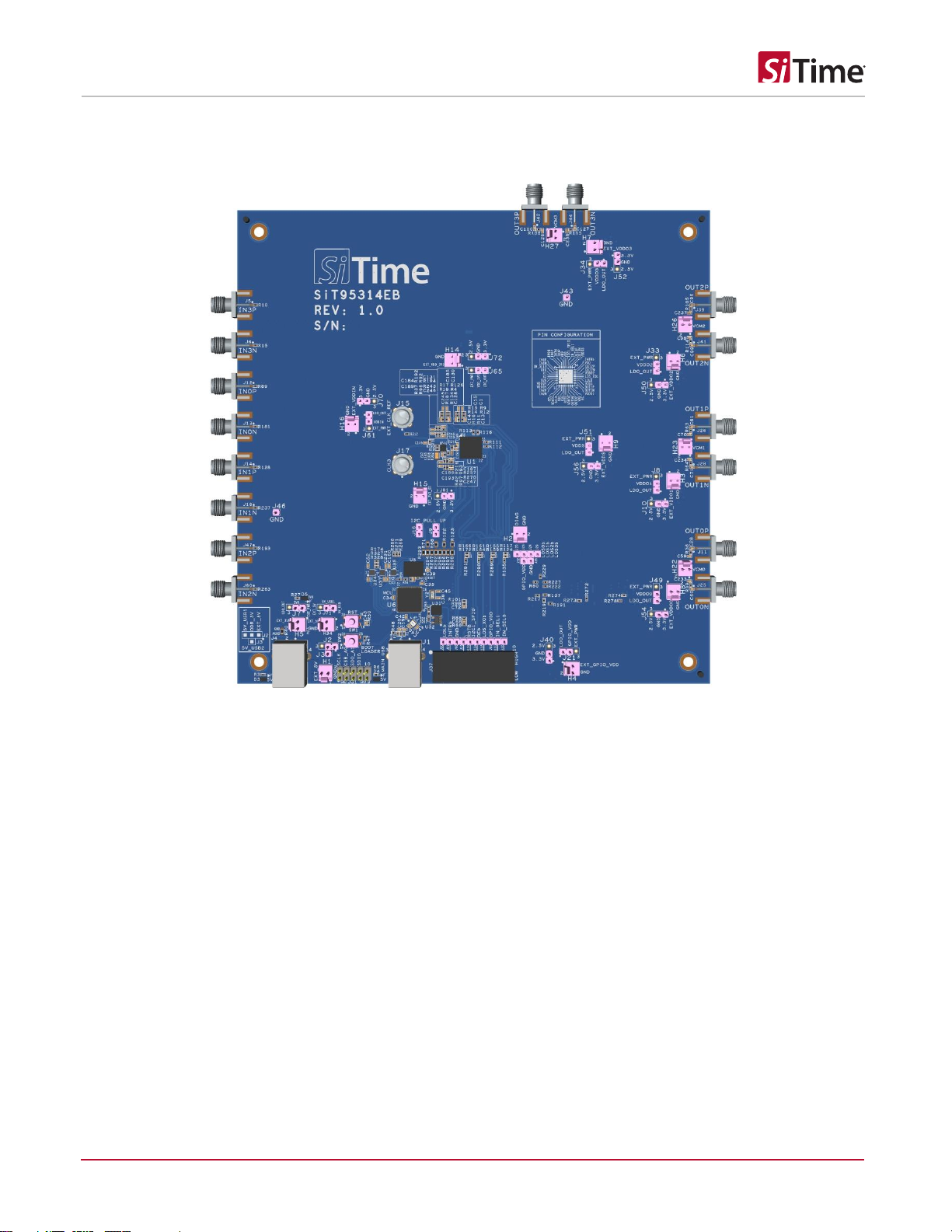
The SiT95314 Evaluation Board is designed for evaluating the SiT95314 Quad PLL Frequency Translator, Jitter Cleaner.
Figure 1. SiT95314 EVK Board
2 Features
1) Support SiT95314 part
2) Powered from USB Port or External Power supply
3) 4 Differential Output Clocks supporting wide frequency range
a. Differential Output from 0.5 Hz to 2.94912 GHz
b. Single Ended Output from 0.5 Hz to 250 MHz
c. Differential Input from 8 KHz to 2.1 GHz
d. Single Ended Input from 8 KHz to 250 MHz
4) Support LVPECL, CML, HCSL, LVDS and LVCOMS Output Standards
5) Status LEDs for power supplies
6) SMA connectors for input clocks, output clocks and external reference clock/XO Input clock
7) I2C or SPI communication via MS430 MCU
8) On board LDO’s with configurable jumpers for all Power supplies.
9) SiTime Clock GUI to configure the EVK via USB
10) Additonal USB Support for powering up the 2 Output Drivers

SiT95314 Evaluation Board (EVB) HW User Manual
SiT95314EB User Manual | Rev 0.5
Page 3 of 17
www.sitime.com
3 Top Level Block Diagram
Below is the Top Level Block Diagram for SiT95314 EVK. The Evaluation board can be connected to a PC via the MAIN USB
Connector for programming, control and monitoring. The on board MSP430 MCU is used for I2C/SPI communication from
SiT95314 using SiTime Clock GUI.
Refer to the SiT95314 Clock GUI manual and User Guide for more information.
Figure 2. Top Level Block Diagram
3.1. EVB Starter Guide
Power up the SiT95314 EVB using 5 V Supply from a USB cable connected to the PC where the SiTime Clock GUI is
installed. All the supplies on board are powered from the on board USB connector. There are 2 USB connectors on the
SiT95314 EVK. J1 is the main USB connector that is used for chip communication alongwith supplying power to all the other
subsystems of the chip.
J4 is an additional USB connector that can be used for supplying power to the Output Driver Supplies (ODR_SUPPLY_x) if the
power supplied from J1 is limited ( J1 is limited to ~500 mA as it comes from the USB 2.0 from PC).Default EVK configuration

SiT95314 Evaluation Board (EVB) HW User Manual
SiT95314EB User Manual | Rev 0.5
Page 4 of 17
www.sitime.com
enables the chip subystems to be powered from J1 connector. In order to power the Output Drivers separately from J4
connector, change the J2 default Jumper configuration from 2 to 3 on J2 and connect to J3 and pin 2 of J2. J4 is not installed
by default.
There is an additional provision to power up the Output Drivers from External Supply as well. To connect an external power
supply, change the default EVK configuration on J2 from 2 to 3 to 1 to 2.
The external Power supply can be connected to H1 2 pin Header (Refer Section 7)
The default Jumper configuration is already done on the EVK board (Refer to Table 1).
Launch the SiTime Clock GUI Software. (Refer to SiTime Clock GUI User Guide for more information)
Default Output Driver Configuration is LVDS and Output Driver Supplies are configured to 3.3 V.
Default Supply for VDD = 1.8 V and VDDIN = 3.3 V.
SiT95314 chip on the EVK can be configured to communicate through I2C/SPI after configuring the same from SiTime
SiT95314 Clock GUI.
Figure 3. EVB Starter Connection Diagram

SiT95314 Evaluation Board (EVB) HW User Manual
SiT95314EB User Manual | Rev 0.5
Page 5 of 17
www.sitime.com
4 Jumper Default List
Table 1. SiT95314 Jumper Default List
Jumper location
Type
I=Installed
Jumper location
Type
I=Installed
J2
4 -Pin
2 to 3
J49
3 -Pin
1 to 2
J7
3 -Pin
2 to 3
J54
3 -Pin
1 to 2
J71
3 -Pin
1 to 2
J51
3 -Pin
1 to 2
J65
3 -Pin
1 to 2
J56
3 -Pin
1 to 2
J61
3 -Pin
1 to 2
J72
3 -Pin
O
J70
3 -Pin
1 to 2
J40
3 -Pin
O
J9
2 -Pin
I
J21
3 -Pin
1 to 2
J16
2 -Pin
I
J50
3 -Pin
1 to 2
J8
3 -Pin
1 to 2
J33
3 -Pin
1 to 2
J10
3 -Pin
1 to 2
J81
3-Pin
O
J34
3 -Pin
1 to 2
J52
3 -Pin
1 to 2
5 Status LEDs
Table 2. Status LED Indication
Location
Color
Status Indication
D3
Green
5V Additional USB Power
D4
Green
5V Main USB Power
D5
Green
MSP430 LDO Power
Figure 4. Status LEDs
SiT95314 Evaluation Board (EVB) HW User Manual
SiT95314EB User Manual | Rev 0.5
Page 6 of 17
www.sitime.com
6 I2C/SPI On Board/External Configuration
The SiT95314 chip can be configured to communicate with I2C and SPI 4 Wire with SiTime SiT95314 Clock GUI. The default
EVK configuration will enable the I2C communication with the chip.
To change the communication to SPI 4 Wire, it is preferable to remove the jumpers J9 and J16.
External Hardware can also be used to communicate with the SiT95314 chip in I2C/SPI using the J31 connector. When using
external connection option, remove R267, R293, R295 and R297 and solder R292, R294, R296 and R298 ( each 0 Ω) to
enable the external interface to the chip using J31.
7 SiT95314 EVK Board Power Supply Connection Details
The power supplies on the EVK are configured to 3.3 V by default except the VDD supply which is set to 1.8 V.The on board
supplies/LDO’s are also configurable to 1.8 V and 2.5 V.
There is a provision for connecting external supplies after bypassing the on board regulators for all the supplies.
Please refer to SiT95314 datasheet for configuring the supply voltages on the various Power Supply rails.
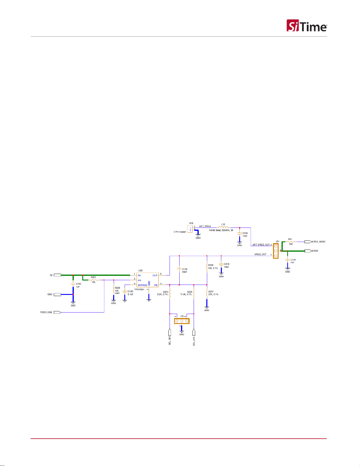
7.1. VDDIN and VDDOX Supply Regulator
Figure 5. Supply Regulator for VDDIN and VDDoX Supply
Note: For changing the LDO Output Power Supply Voltage, connect the corresponding Jumpers (for ex- J70) in Figure 5 to below
settings:
1. 3.3 V - Connect the 3-Pin Jumper from 1 to 2.
2. 2.5 V - Connect the 3-Pin Jumper from 2 to 3.
3. 1.8 V - Remove the Jumper.

SiT95314 Evaluation Board (EVB) HW User Manual
SiT95314EB User Manual | Rev 0.5
Page 7 of 17
www.sitime.com
7.2. VDD Supply Regulator
Figure 6. Supply Regulator for VDD Supply
Note: For changing the VDD (for ex- J72) Supply, connect the Jumper to below settings:
1. 3.3 V - Connect the 3-Pin Jumper from 2 to 3.
2. 2.5 V -Connect the 3-Pin Jumper from 1 to 2.
3. 1.8 V -Remove the Jumper.
VDD should be configured to 1.8V by default.

SiT95314 Evaluation Board (EVB) HW User Manual
SiT95314EB User Manual | Rev 0.5
Page 8 of 17
www.sitime.com
7.3. GPIO_VDD Supply Regulator
Figure 7. Supply Regulator for GPIO_VDD Supply
Note: For changing the GPIO_VDD (for ex- 40) Supply, connect the Jumper to below settings:
1. 3.3 V - Connect the 3-Pin Jumper from 2 to 3.
2. 2.5 V - Connect the 3-Pin Jumper from 1 to 2.
3. 1.8 V - Remove the Jumper.
GPIO_VDD is configured to 1.8V by default.
Based on SiT95314 GUI configuration, VDDIO supply (Internal supply for IO rail) can be configured to follow either VDD(1.8V)
or VDDIN(3.3V). When VDDIO supply is configured to follow VDDIN(3.3V), GPIO_VDD supply jumper J40 needs to be
changed from open to 1-2.
SiT95314 Evaluation Board (EVB) HW User Manual
SiT95314EB User Manual | Rev 0.5
Page 9 of 17
www.sitime.com
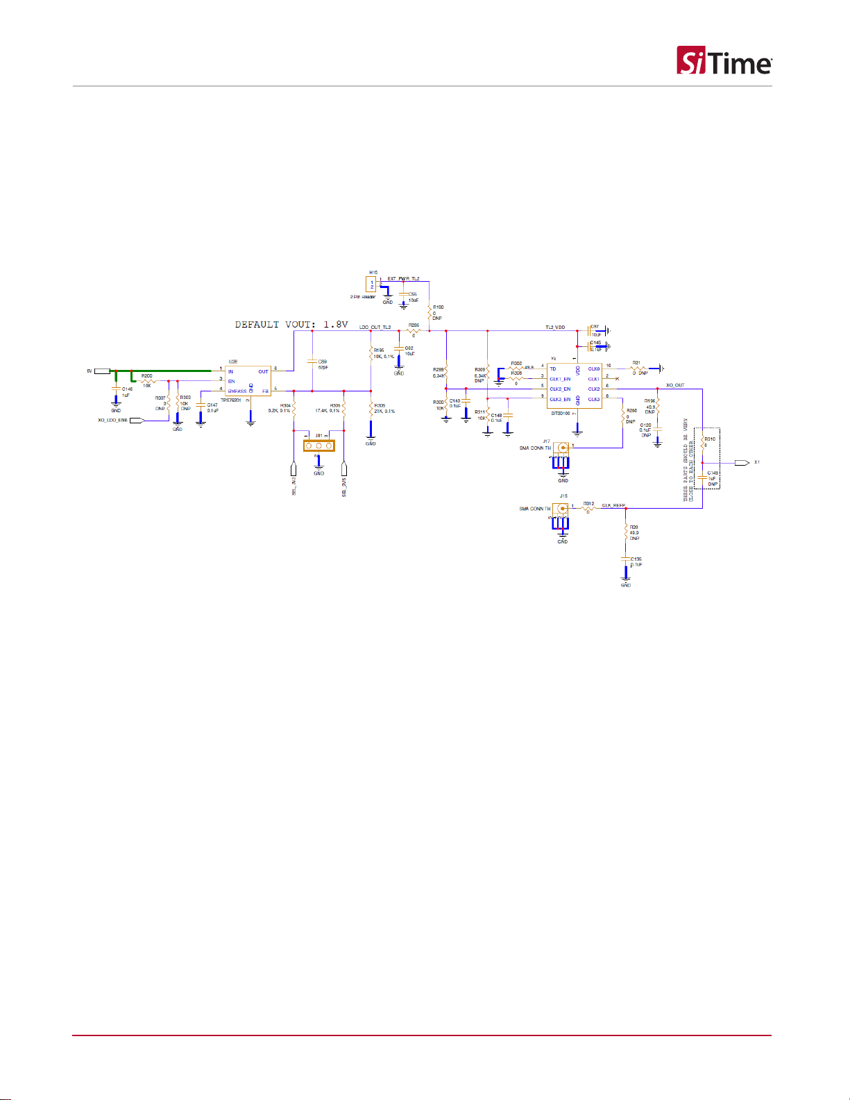
8 External Clock Reference Input (X1/X2)
The SiT95314 EVB has the SiT30100 oscillator (Y4) soldered for providing a stable reference clock to SiT95314.
The EVB can also connect to an external reference clock using the SMA connector(J15).
For changing from SiT30100 oscillator to external reference clock configuration, uninstall R310(0 Ω) and install C149(1uF).
Refer to the SiT95314 datasheet for the XO Pathway connection options.
Figure 8. External Reference Connection
SiT95314 Evaluation Board (EVB) HW User Manual
SiT95314EB User Manual | Rev 0.5
Page 10 of 17
www.sitime.com
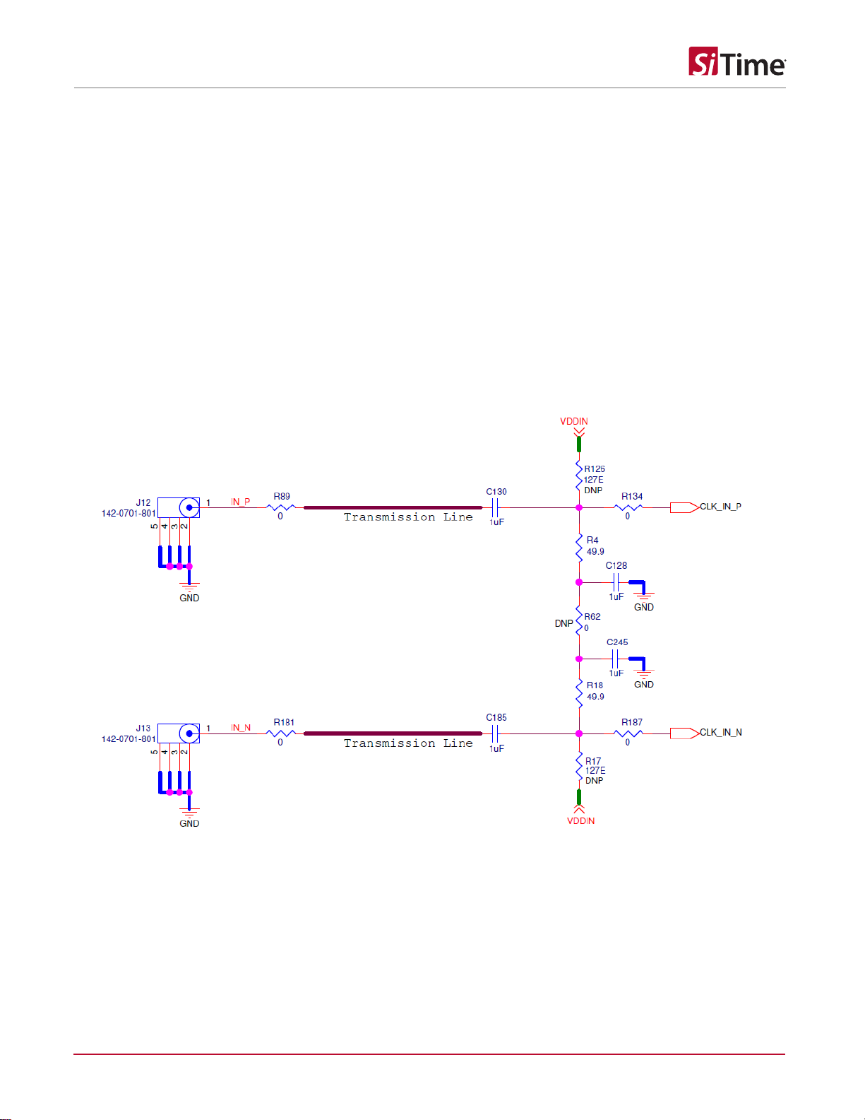
9 Input Clock Circuitry (INx_P/INx_N)
The SiT95314 EVB has 4 Differential Inputs and 8 Single Ended Inputs (IN0P/IN0N, IN1P/IN1N, IN2P/IN2N, IN3P/IN3N) for
receiving the external clock input signals. The input clock termination arrangement is shown in Figure 9. All the Input clocks
are AC Coupled and having single ended 50 Ω terminations by default. The Inputs can be configured either to work as Single
Ended(AC/DC) or Differential(AC/DC) based on the required configuration.
Input Clocks can be configured as:
11) Single Ended AC Coupled ( with the default EVK Input Termination Connection)
12) Single Ended DC Coupled ( Change C130 (1uF) to 0 ohms short –R4 and R18 can also be removed if the Single
Ended External Source is not able to drive the 50 ohms load)
13) Differential DC Coupled ( connect R62 also apart from the default EVK Input termination Connection)
14) Differential AC Coupled (with the default EVK Input Termination Connection)
Refer to the SiT95314 Datasheet for the Single Ended and Differential Input Termination connection information.
Figure 9. Input Clock Termination Circuit

SiT95314 Evaluation Board (EVB) HW User Manual
SiT95314EB User Manual | Rev 0.5
Page 11 of 17
www.sitime.com
10 Output Clock Circuitry (OUTxP/OUTxN)
The SiT95314 EVK has 2 differential Outputs which are AC coupled by default to its respective SMA connector. The Output
Clock Termination is shown in Figure 10.
In case DC coupling is required, the AC coupling capacitors can be replaced by a 0 ohm resistor.
Refer to the SiT95314 datasheet for the Output Termination Connection information.
Figure 10. Output Clock Termination Circuit
SiT95314 Evaluation Board (EVB) HW User Manual
SiT95314EB User Manual | Rev 0.5
Page 12 of 17
www.sitime.com
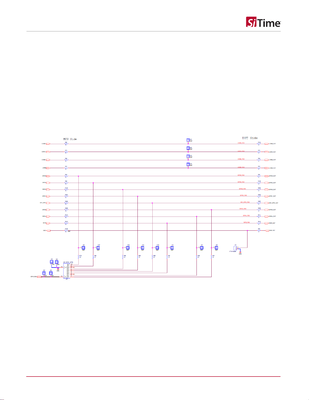
11 GPIO Configuration
The GPIO’s on the chip are by default configured by the on board MSP430 and can be used to set the status as High or Low
by using the GUI Console(Refer to SiTime SiT95314 Clock GUI User Guide)
The GPIO status when configured from the chip can also be read back using the MSP430 in the default EVK configuration.
There is also a provision to control the status using the DIP_SPDT(J37) Switch but whenever DIP_SPDT switch is being used
to control/set the GPIO voltage on the chip, the MCU side GPIO resistors should be removed to make sure there is no
contention on the GPIO bus.
For example, if GPIO1/OEB in Figure 11 needs to be controlled from J104, R204 needs to be removed. The GPIO status can
be manually measured using the berg pin connectors placed near to the J37 switch for each of the GPIO’s.
Figure 11. GPIO Control Status
SiT95314 Evaluation Board (EVB) HW User Manual
SiT95314EB User Manual | Rev 0.5
Page 13 of 17
www.sitime.com
12 EEPROM Configuration
The SiT95314 EVK has on board EEPROM that shares the same I2C bus as the chip. The EEPROM can be flashed externally
or using the on board MSP430 and the EEPROM contents can be further readback from the chip. Refer to the SiT95314
Datasheet for the EEPROM configuration.
13 MSP430 Programming Instructions
The SiT95314 EVK uses the MSP430 to communicate to the chip via I2C/SPI and is also used to configure/read the FLEXIO
status of the chip. The MSP430 firmware is also version controlled and flashed to the MSP430 to handle multiple functions on
the EVK.
In the rare event of a firmware update required for the MSP430, please follow the below steps to upgrade the MCU firmware:
1) The HOST_USB software can be downloaded from path:
Download Software at:
https://software-dl.ti.com/msp430/msp430_public_sw/mcu/msp430/MSP430Ware/3_80_09_03/ _FDS.html
MSP430 Programming Procedure:
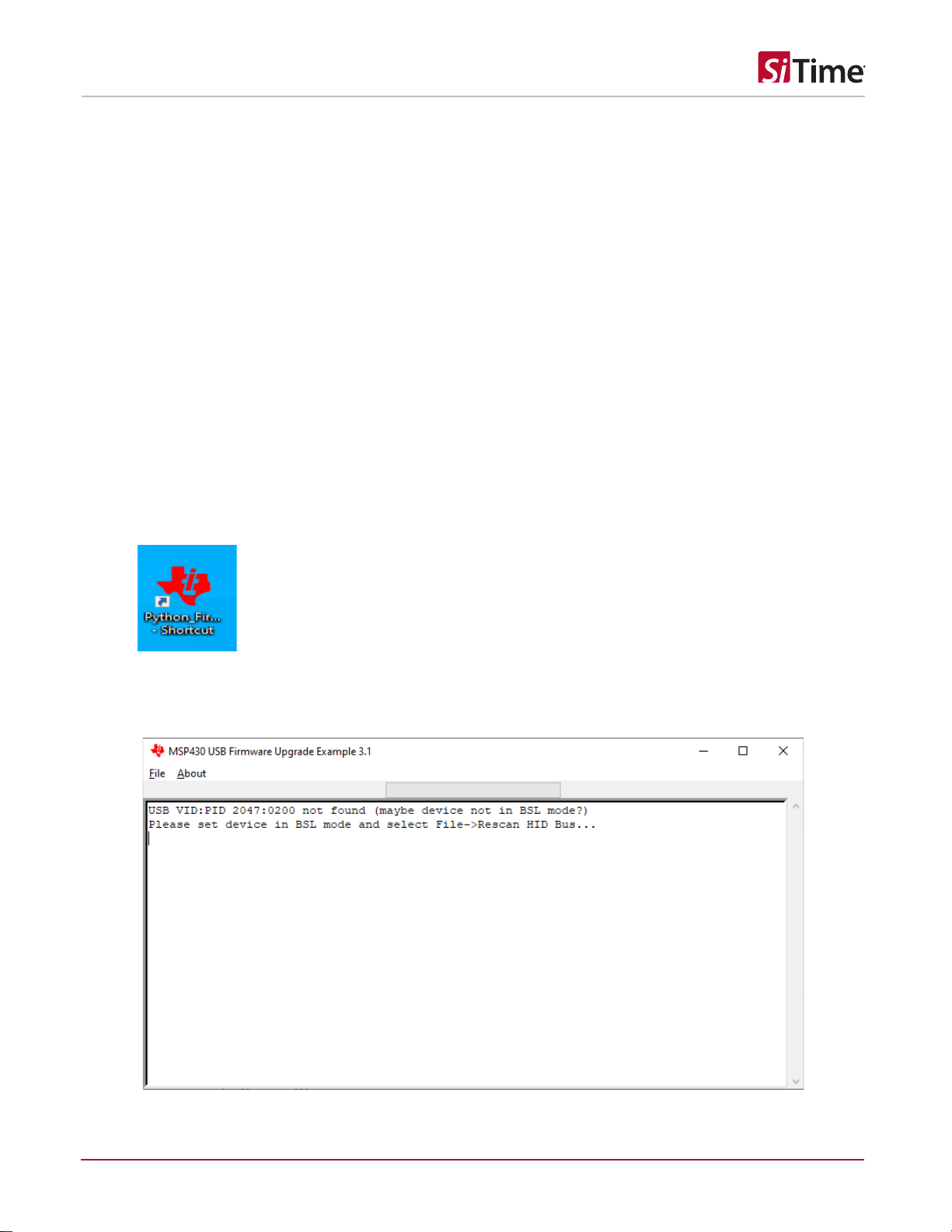
2) Open the GUI from –
C:\ti\msp\MSP430Ware_3_80_07_00\usblib430\Host_USB_Software\Python_Firmware_Upgrader
3) Connect the board to supply and USB using micro USB cable. Reset the chip by pressing ‘SW1’ and ‘SW2’ together.
4) This will take MSP430 to programming mode.
5) If MSP430 is not detected, then the GUI will appear as shown below:


SiT95314 Evaluation Board (EVB) HW User Manual
SiT95314EB User Manual | Rev 0.5
Page 16 of 17
www.sitime.com
10) Select the firmware. The tool should load the firmware into the MCU and and show a completion message as shown:
14 SiTime Clock GUI Installation and EVB Configuration
SiTime SiT95314 Clock GUI provides an easy interface to verify the performance of chip in the lab. The GUI uses the MSP430
microcontroller for the USB to I2C/SPI communication on the board, the MSP430 MCU related software drivers are also
configured while installing the GUI.
Refer to the SiTime SiT95314 Clock GUI User Guide for detailed Installation and EVB configuration instructions.

SiT95314 Evaluation Board (EVB) HW User Manual
SiT95314EB User Manual | Rev 0.5
Page 17 of 17
www.sitime.com
Table 3. Revision History
Revisions
Release Date
Change Summary
0.5
14-Feb-2024
Initial Release
SiTime Corporation, 5451 Patrick Henry Drive, Santa Clara, CA 95054, USA | Phone: +1-408-328-4400 | Fax: +1-408-328-4439
© SiTime Corporation February 2024. The information contained herein is subject to change at any time without notice. SiTime assumes no responsibility or liability for any loss, damage
or defect of a Product which is caused in whole or in part by (i) use of any circuitry other than circuitry embodied in a SiTime product, (ii) misuse or abuse including static discharge, neglect or
accident, (iii) unauthorized modification or repairs which have been soldered or altered during assembly and are not capable of being tested by SiTime under its normal test conditions, or (iv)
improper installation, storage, handling, warehousing or transportation, or (v) being subjected to unusual physical, thermal, or electrical stress.
Disclaimer: SiTime makes no warranty of any kind, express or implied, with regard to this material, and specifically disclaims any and all express or implied warranties, either in fact or by
operation of law, statutory or otherwise, including the implied warranties of merchantability and fitness for use or a particular purpose, and any implied warranty arising from course of dealing or
usage of trade, as well as any common-law duties relating to accuracy or lack of negligence, with respect to this material, any SiTime product and any product documentation. Products sold by
SiTime are not suitable or intended to be used in a life support application or component, to operate nuclear facilities, or in other mission critical applications where human life may be involved
or at stake. All sales are made conditioned upon compliance with the critical uses policy set forth below.
CRITICAL USE EXCLUSION POLICY
BUYER AGREES NOT TO USE SITIME'S PRODUCTS FOR ANY APPLICATION OR IN ANY COMPONENTS USED IN LIFE SUPPORT DEVICES OR TO OPERATE NUCLEAR
FACILITIES OR FOR USE IN OTHER MISSION-CRITICAL APPLICATIONS OR COMPONENTS WHERE HUMAN LIFE OR PROPERTY MAY BE AT STAKE.
SiTime owns all rights, title and interest to the intellectual property related to SiTime's products, including any software, firmware, copyright, patent, or trademark. The sale of SiTime products
does not convey or imply any license under patent or other rights. SiTime retains the copyright and trademark rights in all documents, catalogs and plans supplied pursuant to or ancillary to
the sale of products or services by SiTime. Unless otherwise agreed to in writing by SiTime, any reproduction, modification, translation, compilation, or representation of this material shall be
strictly prohibited.
Table of contents
Other SiTime Motherboard manuals

SiTime
SiTime SiT6760EB User manual

SiTime
SiTime SiT6503EB User manual

SiTime
SiTime SiT6731EB User manual

SiTime
SiTime SiT6098EBB User manual

SiTime
SiTime SiT6731EB User manual

SiTime
SiTime SiT6712EB User manual

SiTime
SiTime SiT92216 User manual

SiTime
SiTime SiT6722EB User manual

SiTime
SiTime SiT6098EBB User manual

SiTime
SiTime Time Machine II User manual


